Cushioning Mechanism For A Treadmill
Kueker; Jared M.
U.S. patent application number 16/582056 was filed with the patent office on 2020-03-26 for cushioning mechanism for a treadmill. The applicant listed for this patent is True Fitness Technology, Inc.. Invention is credited to Jared M. Kueker.
| Application Number | 20200094105 16/582056 |
| Document ID | / |
| Family ID | 69883027 |
| Filed Date | 2020-03-26 |


| United States Patent Application | 20200094105 |
| Kind Code | A1 |
| Kueker; Jared M. | March 26, 2020 |
CUSHIONING MECHANISM FOR A TREADMILL
Abstract
A cushioning system for an exercise device such as a treadmill, and particularly a slat treadmill, that utilizes a springboard effect in mounting the tread deck to provide cushioning to the running surface.
| Inventors: | Kueker; Jared M.; (St. Charles, MO) | ||||||||||
| Applicant: |
|
||||||||||
|---|---|---|---|---|---|---|---|---|---|---|---|
| Family ID: | 69883027 | ||||||||||
| Appl. No.: | 16/582056 | ||||||||||
| Filed: | September 25, 2019 |
Related U.S. Patent Documents
| Application Number | Filing Date | Patent Number | ||
|---|---|---|---|---|
| 62736277 | Sep 25, 2018 | |||
| Current U.S. Class: | 1/1 |
| Current CPC Class: | A63B 22/0221 20151001; A63B 22/0285 20130101 |
| International Class: | A63B 22/02 20060101 A63B022/02 |
Claims
1. A running deck for a treadmill comprising: a support structure having a first belt roller disposed toward a first end thereof and a second belt roller disposed toward a second opposing end thereof; a roller frame including a plurality of roller bearings and disposed between said first belt roller and said second belt roller; a continuous belt disposed around said first belt roller and said second belt roller and rolling on said roller bearings; a hinge support disposed toward said first end of said support structure and rotationally coupling said roller frame to said support structure; and a compression support disposed toward said second end of said support structure; wherein, when a force is applied to said continuous belt rolling on said roller bearings, said roller frame rotates at said hinge support compressing said compression support.
2. The running deck of claim 1 wherein said support structure comprises sidewalls.
3. The running deck of claim 1 wherein said continuous belt comprises a plurality of connected slats.
4. The running deck of claim 1 wherein said continuous belt comprises a fabric belt.
5. The running deck of claim 1 wherein said first belt roller comprises a toothed cog.
6. The running deck of claim 5 wherein said second belt roller comprises a toothed cog.
7. The running deck of claim 1 wherein said compression support comprises a mechanical spring.
8. The running deck of claim 1 wherein said compression support comprises an electromagnet.
9. The running deck of claim 1 wherein said first end comprises a front end of said treadmill relative to a user walking thereon.
10. The running deck of claim 1 wherein said second end comprises a front end of said treadmill relative to a user walking thereon.
11. A treadmill comprising: a running deck comprising: a first belt roller and a second belt roller disposed toward opposing ends of said running deck; a roller frame including a plurality of roller bearings and disposed between said first belt roller and said second belt roller; a continuous belt disposed around said first belt roller and said second belt roller and rolling on said roller bearings; a hinge support disposed toward said first end of said support structure and rotationally coupling said roller frame to said support structure; and a compression support disposed toward said second end of said support structure; a support frame; and a control panel; wherein, when a force is applied to said continuous belt rolling on said roller bearings, said roller frame rotates at said hinge support relative to said support frame and compresses said compression support;
12. The treadmill of claim 11 wherein said support structure comprises sidewalls.
13. The treadmill of claim 11 wherein said continuous belt comprises a plurality of connected slats.
14. The treadmill of claim 11 wherein said continuous belt comprises a fabric belt.
15. The treadmill of claim 11 wherein said first belt roller comprises a toothed cog.
16. The treadmill of claim 15 wherein said second belt roller comprises a toothed cog.
17. The treadmill of claim 11 wherein said compression support comprises a mechanical spring.
18. The treadmill of claim 11 wherein said compression support comprises an electromagnet.
19. The treadmill of claim 11 wherein said first end comprises a front end of said treadmill relative to a user walking thereon.
20. The treadmill of claim 11 wherein said second end comprises a front end of said treadmill relative to a user walking thereon.
Description
CROSS REFERENCE TO RELATED APPLICATION(S)
[0001] This application claims the benefit of U.S. Provisional Patent Application Ser. No. 62/736,277, filed Sep. 25, 2018, the entire disclosure of which is herein incorporated by reference.
BACKGROUND OF THE INVENTION
1. Field of the Invention
[0002] This disclosure relates to cushioning systems for exercise devices, such as treadmills. Specifically, the cushioning system is intended for a slat treadmill or similar treadmill which utilizes rollers in the support for the tread belt.
2. Description of the Related Art
[0003] Today's conventional treadmills typically operate by employing a motor to rearwardly drive an endless belt upon which the user runs, walks, or otherwise engages in ambulatory leg movement, generally in a direction opposing the motion of the belt. As the user is moving in opposition to the belt, the user therefore "moves" in order to remain in place. Generally, a user of a conventional treadmill is able to vary the speed of the treadmill to obtain a desired level of workout by increasing the speed of the motor to accelerate the speed of the belt and increase their necessary movement speed. Alternatively, the user can make the workout more difficult by increasing the incline to simulate moving uphill. More sophisticated motorized treadmills, such as those described in U.S. Pat. No. 5,462,504, the entire disclosure of which is herein incorporated by reference, automatically adjust the speed and incline of the treadmill to control the heart rate of the user during the exercise.
[0004] Conventional treadmills of this type function to exercise the user's cardiovascular system (cardio exercise) and, to some extent, the skeletal muscles of the lower body. However, these types of treadmills, while simulating the exertion of walking or running, do not actually exercise the user in the same way a user exercises when actually running or walking. To provide a different type of motion and attempt to fill this gap, there are also treadmills which do not use a motor to supply the belt's rotary motion. In many cases, these do not actually use a belt at all but use a series of rollers and a "slat-type" conveyor in the form of a chain belt. These types of machines rely on the user of the treadmill to provide their own locomotion which is then imparted to the belt and rollers. To allow for continuous in-place motion, self-powered or "motorless" treadmills traditionally are designed to support the endless belt on some incline such that the belt rotates rearwardly as a result of the weight and forward stride of the user overcoming belt friction. In effect, these types of treadmills add some resistance to the walking or running motion through the use of the internal friction of the components and the need for the user to utilize their leg muscles to propel the belt or chain.
[0005] While they are often self-powered, "slat" treadmills can be motorized. However, they will still conventionally utilize conveyor chains formed from a plurality of slats instead of a single endless belt and that presents some unique design problems. In a typical slat treadmill, the slats are built from aluminum "T" shaped pieces that are overmolded by rubber or another high grip and compactable surface and then connected to each other by being secured onto a belt at the edge of the slats. Typical belts for slat treadmills comprise two portions. The first portion of a typical belt may include features designed to interface with a cog (or other rotation-assisting means known in the art) at both ends of the frame until the slats from a continuous loop in order to facilitate the rotation of the belt. The first section may be formed towards the end of the belt that is closest to the exterior of the slat treadmill. The second portion of a typical belt may include a flat, or relatively featureless, portion that interfaces with an idler wheel. The communication between the second portion of the typical belt and the idler wheel may assist the slat treadmill in reducing vibrations communicated between the frame and the loop of slats and in reducing stress imparted on the cog teeth from the belt. At the ends of the frame, this loop rolling around the cog helps to control the speed of the user and control the tension to make sure that the belt or chain does not slip.
[0006] Between these cogs at the ends of the frame, there are commonly one or two rows of small roller bearings often toward the edges of the slats which provide the support for the slats on the tread deck. These rollers both allow the conveyor chain to move freely and also provide enough support so that there little to no deflection of the slats when a user runs on the tread surface.
[0007] Slat treadmills often utilize roller components which are designed to move with relatively little resistance. Thus, the tread deck is generally formed of a number of independent roller bearings comprising generally cylindrical rollers. These rollers are commonly mounted on axles utilizing ball bearings or other low friction connections so that they readily rotate. In this way a user standing on the belt and pushing it into the tread deck does not create substantial friction between the tread deck and the belt which they would have to overcome as they begin to exercise. Instead, the relatively heavy and potentially high friction belt is supported on a surface of highly rotatable bearing supports and turns quite easily.
[0008] While this provides for a reduction of friction when the slats are rotated about the main rollers, the frames supporting the rollers are typically rigidly mounted to the rest of the frame of the treadmill. This structure provides virtually no softness in the unit as rigid slats are in contact with rigid roller bearings rigidly mounted to a frame which is positioned on the rigid floor surface the treadmill is resting on. This creates an extremely firm feeling machine which can cause discomfort while running.
[0009] In addition to discomfort, the firmness of the machine can present a possibility of injury. In typical treadmills that utilize slats and rollers, the treadmill behaves more like the ground than a typical treadmill deck of a motorized treadmill. Further, the rigid structure of the slats and rollers creates a surface more like running on concrete or asphalt as opposed to running on modern track surfaces or grass. It is well establishes that the pounding of the feet hitting such a rigid surface can cause injury such as to joints in the knees or hips which can make such treadmills unsuitable for a wide array of users. This means that while non-motorized slat-type treadmills can provide for a specific type of workout more like that provided by actual running, the workout often includes many of the detriments and not just the positives resulting in a machine which can be difficult to use effectively.
SUMMARY OF THE INVENTION
[0010] The following is a summary of the invention, which should provide to the reader a basic understanding of some aspects of the invention. This summary is not intended to identify critical elements of the invention or in any way to delineate the scope of the invention. The sole purpose of this summary is to present in simplified text some aspects of the invention as a prelude to the more detailed description presented below.
[0011] Because of these and other problems in the art, discussed herein is a cushioning system for a treadmill, and particularly a slat treadmill, that utilizes a springboard effect in mounting the tread deck to provide cushioning to the running surface.
[0012] Described herein, among other things, is a running deck for a treadmill comprising: a support structure having a first belt roller disposed toward a first end thereof and a second belt roller disposed toward a second opposing end thereof; a roller frame including a plurality of roller bearings and disposed between the first belt roller and the second belt roller; a continuous belt disposed around the first belt roller and the second belt roller and rolling on the roller bearings; a hinge support disposed toward the first end of the support structure and rotationally coupling the roller frame to the support structure; and a compression support disposed toward the second end of the support structure; wherein, when a force is applied to the continuous belt rolling on the roller bearings, the roller frame rotates at the hinge support compressing the compression support.
[0013] In an embodiment of the running deck, the support structure comprises sidewalls.
[0014] In an embodiment of the running deck, the continuous belt comprises a plurality of connected slats.
[0015] In an embodiment of the running deck, the continuous belt comprises a fabric belt.
[0016] In an embodiment of the running deck, one or both of the first belt roller and the second belt roller comprises a toothed cog.
[0017] In an embodiment of the running deck, the compression support comprises a mechanical spring.
[0018] In an embodiment of the running deck, the compression support comprises an electromagnet.
[0019] In an embodiment of the running deck, the first end comprises a front end of the treadmill relative to a user walking thereon.
[0020] In an embodiment of the running deck, the second end comprises a front end of the treadmill relative to a user walking thereon.
[0021] There is also described herein, an embodiment of a treadmill comprising: a running deck comprising: a first belt roller and a second belt roller disposed toward opposing ends of the running deck; a roller frame including a plurality of roller bearings and disposed between the first belt roller and the second belt roller; a continuous belt disposed around the first belt roller and the second belt roller and rolling on the roller bearings; a hinge support disposed toward the first end of the support structure and rotationally coupling the roller frame to the support structure; and a compression support disposed toward the second end of the support structure; a support frame; and a control panel; wherein, when a force is applied to the continuous belt rolling on the roller bearings, the roller frame rotates at the hinge support relative to the support frame and compresses the compression support;
[0022] In an embodiment of the treadmill, the support structure comprises sidewalls.
[0023] In an embodiment of the treadmill, the continuous belt comprises a plurality of connected slats.
[0024] In an embodiment of the treadmill, the continuous belt comprises a fabric belt.
[0025] In an embodiment of the treadmill, at least one of the first belt roller and second belt roller comprises a toothed cog.
[0026] In an embodiment of the treadmill, the compression support comprises a mechanical spring.
[0027] In an embodiment of the treadmill, the compression support comprises an electromagnet.
[0028] In an embodiment of the treadmill, the first end comprises a front end of the treadmill relative to a user walking thereon.
[0029] In an embodiment of the treadmill, the second end comprises a front end of the treadmill relative to a user walking thereon.
BRIEF DESCRIPTION OF THE DRAWINGS
[0030] FIG. 1 provides a perspective view of an embodiment of running deck for a slat treadmill exercise machine including a cushioning system as contemplated herein.
[0031] FIG. 2 provides a side view of the rear of the embodiment of FIG. 1 with the outer frame removed showing the roller frame with the slats thereon.
[0032] FIG. 3 provides a side view of the embodiment of FIG. 1 with the outer frame removed showing the roller frame and cushion support relative positioning.
[0033] FIG. 4 depicts a detail of the rotational connection toward the rear of the exercise machine of FIG. 3.
[0034] FIG.5 depicts a detail view of the cushioning support toward the front of the exercise machine of FIG. 3.
[0035] FIG. 6 depicts a perspective view of the embodiment of FIG. 3.
[0036] FIG. 7 depicts a cut-through image of an embodiment of a treadmill including an embodiment of a running deck.
DETAILED DESCRIPTION OF THE PREFERRED EMBODIMENT(S)
[0037] It should be recognized that the disclosure herein is focused on treadmills which utilize a running belt formed of individual slats (a conveyor chain) interacting with a continuous belt to provide the exercise as this is the device primarily pictured in the FIGS. While this is a valuable exemplary embodiment, one of ordinary skill in the art would understand that such structure is by no means required and the treadmill may use other kinds of belts such as continuous fabric belts or pure conveyor chains. Further, the systems and method discussed herein are also not limited to treadmills. Other types of exercise machines, and particularly those that utilize an endless belt of any form, can utilize the cushioning systems discussed herein.
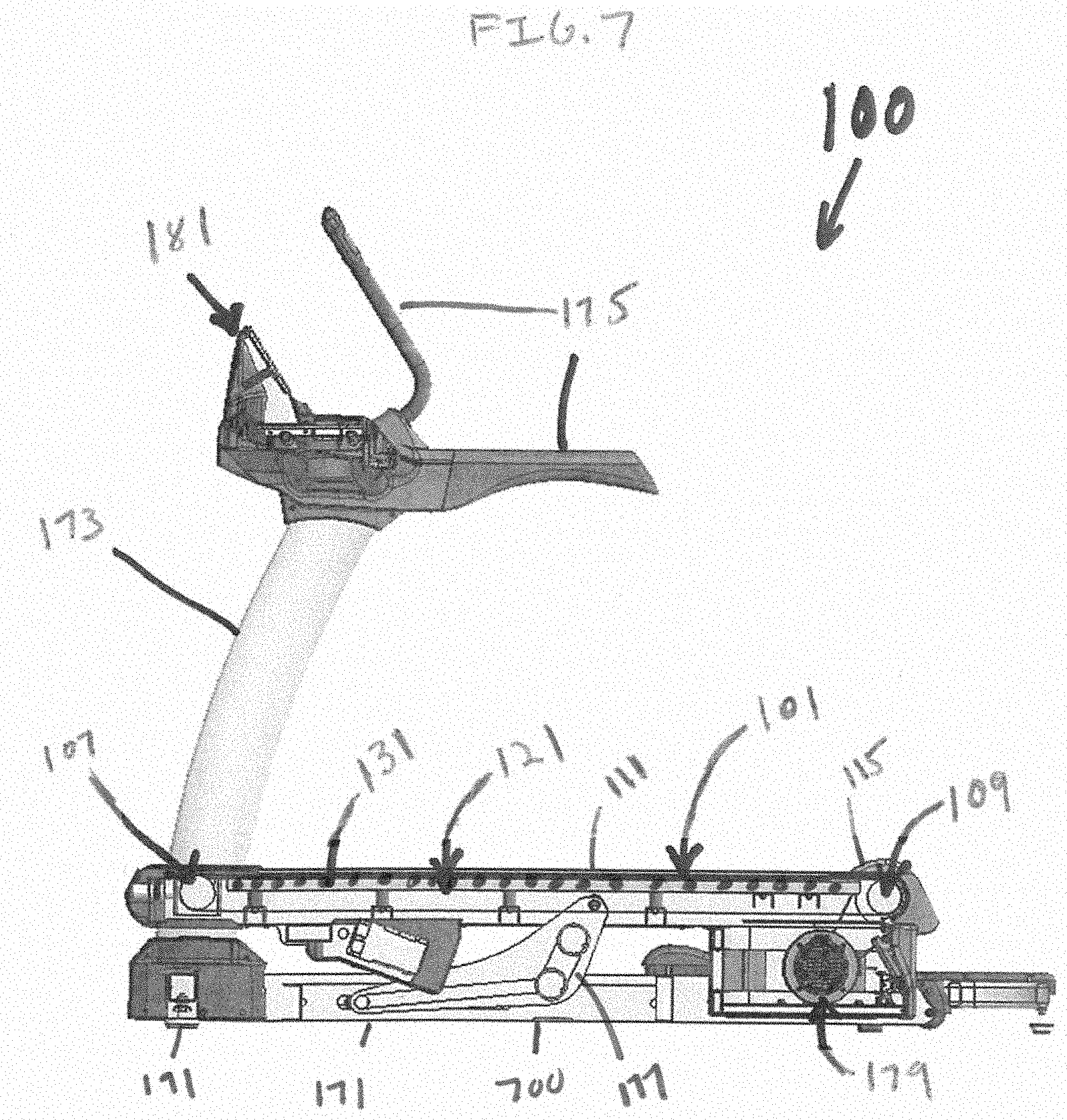
[0038] FIG. 1 provides an embodiment of a running deck (101) of a slat treadmill. The running deck (101) comprises a treadmill chain or belt (111) which is accessible to a user on the running surface (105) thereof The belt (111) is generally positioned between two sidewalls (115) or other support structure which provide for the user to have a place to step on and off the belt (111). These sidewalls (115) also provide for user safety enclosing the moving components supporting and operating the belt (111) from the user and typically are stationary components generally formed as part of the treadmill's support frame. Typically, a user of the running deck (101) will be running or walking toward the right side of the page and this orientation will be maintained throughout the FIGS. However, the orientation of the user is by no means required or fixed and the running deck (101) may be used with either end as the front or rear.
[0039] The running deck (101) will typically be attached to additional frame components (700) to form the resultant treadmill (100) as shown in the embodiment of FIG. 7. These additional frame components (700) may be the typical components of treadmills (100) such as, but not limited to, the floor stand (171), riser (173), and hand grips (175). Further, depending on the particular treadmill design being used, components such as arm drives, lift mechanisms (177), support feet (191), and a motor and/or brake (179) may also be present to provide functionality and usability to treadmills and other exercise machines.
[0040] There will also generally be attached to the treadmill (101) a control system (181), which is connected to a user interface. The user interface may be as simple as dials or buttons, or may be more complex, including touch-activated screens and other computer-like interface features. When a user pushes buttons on the interface or the screen, electrical signals are sent to electrical components of the system such as sensors or motors to control incline, speed, resistance, or other aspects of the running deck (101) or to control other aspects of the treadmill (100).
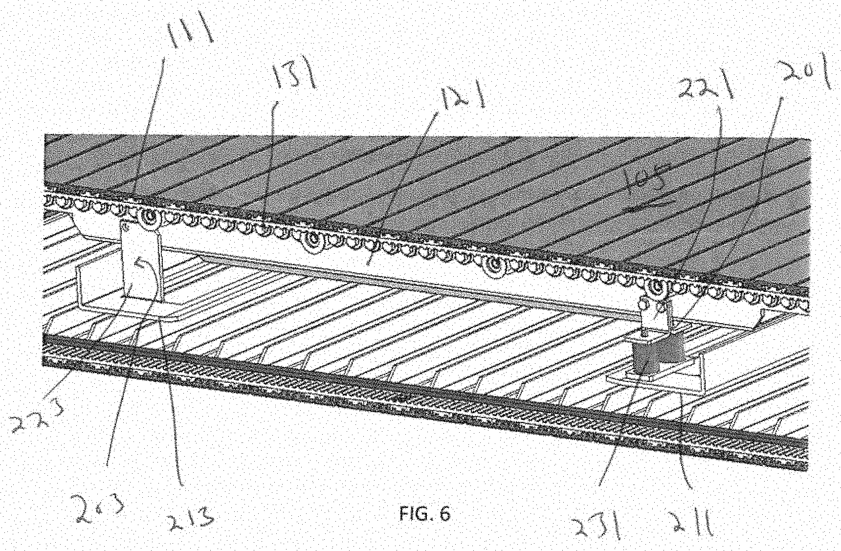
[0041] FIGS. 2-6 provide views of the running deck (101) of FIG. 1 with the sidewalls (115) removed to show internal components. The roller frame (121) is within the loop formed by the continuous belt (111). The belt (111) comprises a plurality of slats (113) upon which the user will run which will generally be attached to an underlying continuous loop of material (123) which serves to provide friction between the slats (113) and the first and second belt rollers (107) and (109). The attachment between the belt (111) and the loop (123) may be considered generally permanent, such as through the use of adhesives, or the parts may be readily separable such as, for instance, if they are simply connected together via a high friction surface. The loop (123) allows for the belt (111) to be given direction and motion by the two belt rollers (107) and (109) with one attached toward each of the opposing ends of the running deck (101). While the present embodiment provides for frictional connection belt rollers (107) and (109), in an alternative embodiment, the first and second belt rollers (107) and (109) may either or both be replaced by toothed cogs. Depending on embodiment, the slat treadmill may be motorized with a motor (179) around location (129) driving the second (front) belt roller (109) and/or a motor (179) around location (127) driving the first (rear) belt roller (107). Alternatively, the slat treadmill may be user powered and not include any motors.
[0042] The roller frame (121) will generally include a plurality of roller bearings (131) which serve to support the belt (111). While the belt (111) will generally be tensioned via the rollers (107) and (109), it should be recognized that a user moving on the belt (111) between the rollers (107) and (109) will generally cause the belt (111) to deflect inward toward and potentially between the rollers (107) and (109) at least some amount and regardless of the amount of tension applied to the belt (111). To avoid damage to the belt (111) or rollers (107) and (109) and to provide sufficient stiffness to the belt (111) to keep the user from sagging into it, the plurality of roller bearings (131) will generally serve to provide a relatively rigid surface that supports the belt (111) as it is passing over the roller frame (121). A user will generally be expected to walk, run, or otherwise engage in ambulatory movement on the belt (111) when it is above the roller frame (121). Therefore, the combination of the roller frame (121) and the plurality of roller bearings (131) will serve to support the user's mass and inhibit deformation of the belt (111) during exercise.
[0043] As can be seen in the FIGS, the connection between the belt (111) and the roller bearings (131) is generally quite rigid. While the loop (123) can provide for some cushioning, such as, but not limited to, by being made of a rubber or similar material, the interface between the rigid structure of the slats (113) and the roller bearings (131) will generally result in a fairly rigid surface (105). Further, while the running deck (101) may be supported by further components relative to the floor, the running deck (101) itself will also be of generally rigid construction.
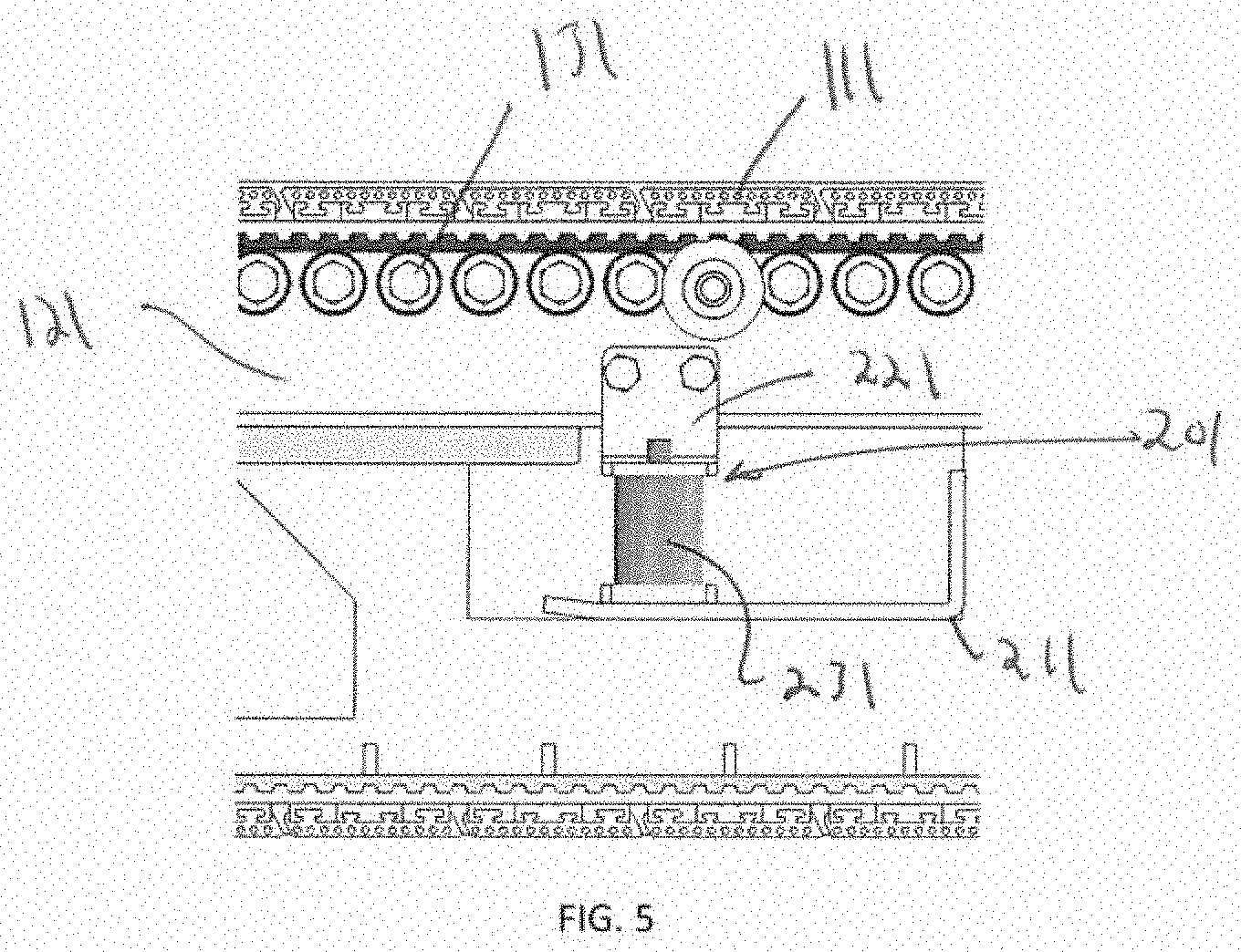
[0044] In order to provide for a cushioning effect to the running deck (101), the roller frame (121) is provided with a cushioning system. The cushioning system generally comprises two connections for interconnecting the roller frame (121) with the primary structure of the running deck (101). Typically, the cushioning system components will be mounted on shelves (211) and (213) which may be rigidly attached to the sidewalls (115). In this way the shelves (211) and (213) are part of the rigid structure of the running deck (101), but will allow the roller frame (121) to partially or completely "float" relative to the rest of the support frame of the treadmill.
[0045] The cushioning system in the depicted embodiment works in the way of a springboard. Specifically the shelf (213) toward the first end or rear of the roller frame (121) includes a hinge support (203) while the shelf (211) toward the second end or front of the roller frame (121) includes a compression support (201). Together, these elements allow for the roller frame (121) to have some bounce which can provide for a softer feel when walking on the belt (111).
[0046] FIG. 4 provides a more detailed view of the hinge support (203). The hinge support (213) will generally be rigidly connected to the shelf (213) and will commonly be in the form of a bracket (223) or something similar. The bracket (223) includes a rotational pin (233) positioned through a hole (243) in the bracket (223). The pin (233) then continues either through a corresponding hole in the roller frame (121) or may be attached to the roller frame (121) in a more rigid fashion. Regardless of connection, the roller frame (121) is allowed to rotate relative to the bracket (223) about an axis of the pin (233) with the pin (233) moving within the hole (243) and/or the corresponding hole in the roller frame (121).
[0047] It should be apparent that FIG. 4 provides only a single embodiment of a hinge support (203) and in alternative embodiments, the hinge support (203) can comprise alternative forms of hinge. The primary structure of the hinge support (203) can be, depending on embodiment, any structure which allows for the roller frame (121) to rotate, tilt, or flex relative to the more rigid support elements of the treadmill such as, but not limited to, the side walls (115). Further, while FIG. 4 shows that the point of rotation (and thus the hinge point) with the more rigid structures of the support frame is located within the loop of the belt (111) and under the roller frame (121), this is not required and in alternative embodiments, the point of rotation may be positioned outside the belt (111) loop including, without limitation, above it, below it, to the side, to the rear, or to the front.
[0048] Further, while the hinge support (203) is also shown as located in the back half of the treadmill (that is between the rear roller (107) and the midpoint of the roller frame (121)) this is also not required and the hinge support (203) may be positioned anywhere that allows for the roller frame (121) to at least partially rotate relative to the support frame of the treadmill.
[0049] FIG. 5 shows a more detail view of the front shelf (211) and the compression support (201). The compression support (201) also generally comprises a bracket (221). However, in this case the bracket (221) is rigidly attached to the roller frame (121) instead of the shelf (211). The bracket (221) is then attached via a spring (231) or similar device to the shelf (211). The spring (231) will generally be in the form of a coiled compression spring where the spring (231) will naturally rest in a biased position where a force is required to compress the coils closer together. However, one of ordinary skill will understand that any type of spring or other mechanism may be used where a force is to move the bracket (221) toward the shelf (211) is resisted by the biasing force of the spring (231). Thus, the spring (231) can include, but is not limited to, any form of mechanical spring, electromagnetic spring (including the use of electromagnetic fields), chemical spring, hydraulic or pneumatic spring, or any similar type of mechanism or combination of mechanisms. Further, while the motion against the compression support (201) contemplated herein is referred to as "compression", one of ordinary skill in the art would readily understand that the compression support (201) could be constructed in a manner that the compression support resisted the identical force with an extension and, therefore, reference to the compression support (201) in no way requires it to "compress" to resist motion, merely that it resist or bias against motion which would be compression of the compression support (201) in a specific embodiment.
[0050] Further as with the hinge support (203), while FIG. 5 shows that the compression support (201) is located within the loop of the belt (111) and under the roller frame (121), this is not required and in alternative embodiments, the point of rotation may be positioned outside the belt (111) loop including, without limitation, above it, below it, to the side, to the rear, or to the front. Further, as with the hinge support (203), while the compression support (201) is shown as located in the front half of the treadmill device (that is between the front roller (107) and the midpoint of the roller frame (121)) this is also not required and the compression support (201) may be positioned anywhere that allows for the roller frame (121) to rotate relative to the support frame of the device.
[0051] In operation, the treadmill will generally operate as follows. A user will be positioned on the surface (105) of the belt (111) and will be running, walking, or otherwise ambulating on the belt. As the user steps forward, their front foot will generally hit forward of their rear foot and will commonly land in the front half of the tread deck (101). The impact of their foot on the belt (111) will be transmitted through the belt (111) and into the roller frame (121) via the rollers (131). The front portion of the roller frame (121) will therefore be depressed in the manner of a lever about the pin (233) causing the spring (231) to compress. The depression of the roller frame (121) is resisted by the damping force of the spring (231) and preferably the spring (231) will not fully compress under the impact.
[0052] Once the footfall has been completed, the user will transfer their weight to the front foot and lift their rear. However, while this is occurring, the movement of the belt (111) rearward will move the users foot away from the compression support (201) and toward the hinge support (203). This movement means that the user is supplying less force on the roller frame (121) in the front half of the roller frame and the torque on the roller frame (121) will generally be reduced even while their weight is being transferred to their front foot increasing the force at that location. The biasing force of the spring (231) will, therefore, begin to return the roller frame (121) back to its initial position, which is generally horizontal relative to the floor unless the tread deck (101) has been purposefully inclined at which time it would push toward such purposeful incline. This will allow the spring (231) to decompress and be ready to compress in response to the next footfall.
[0053] While the above has contemplated that the compression support (201) be located in the front of the tread deck (101) this is by no means required and the compression support (201) may be positioned in any manner commensurate with supplying the resisted rotation of the roller frame (121) about the pin (233). For example, the compression support (201) may comprise a leaf spring positioned under the entire length of the roller frame (121) or may comprise a pneumatic cylinder extending from the hinge support (203) to the bracket (221) where the resistance is provided by the cylinder resisting extension.
[0054] In other embodiments, the compression support (201) and hinge support (203) may be combined into a single support having both functionalities or may be eliminated as separate structures and the roller frame (121) may actually be positioned to provide the functionality through its own flexibility or through the flexibility of a connection between the roller frame (121) and other elements of the support frame. In such an embodiment, the roller frame (121) may be rigidly attached to the support frame at a rearward point such as the location of the hinge support in FIG. 4. The opposing end of the roller frame (121) may then be unsupported and allowed to float, possibly within a constrained area. In this embodiment, the springboard effect is provided solely by the bending and flexing of the roller frame (121) and/or the connection between the roller frame (121) and remaining components. The roller frame (121) in such an embodiment, may be constructed of a material with a desired degree of flexibility to provide a compatible surface for an average mass user so as to provide for some "bounce" without having too much flexibility which may be jarring to the user.
[0055] Still further, while it is generally preferred that the roller frame (121) be supported by a hinge support (203) at one end and a compression support (201) at the other, it should be recognized that this is simply for mechanical simplicity. In an alternative embodiment, the roller frame (121) may actually be attached by two or more compression supports (201) located at different points under the roller frame (121) which can provide additional cushioning based on specifically where footfalls occur.
[0056] The qualifier "generally," and similar qualifiers as used in the present case, would be understood by one of ordinary skill in the art to accommodate recognizable attempts to conform a device to the qualified term, which may nevertheless fall short of doing so. This is because terms such as "sphere" are purely geometric constructs and no real-world component is a true "sphere" in the geometric sense. Variations from geometric and mathematical descriptions are unavoidable due to, among other things, manufacturing tolerances resulting in shape variations, defects and imperfections, non-uniform thermal expansion, and natural wear. Moreover, there exists for every object a level of magnification at which geometric and mathematical descriptors fail due to the nature of matter. One of ordinary skill would thus understand the term "generally" and relationships contemplated herein regardless of the inclusion of such qualifiers to include a range of variations from the literal geometric meaning of the term in view of these and other considerations.
[0057] While the invention has been disclosed in conjunction with a description of certain embodiments, including those that are currently believed to be the preferred embodiments, the detailed description is intended to be illustrative and should not be understood to limit the scope of the present disclosure. As would be understood by one of ordinary skill in the art, embodiments other than those described in detail herein are encompassed by the present invention. Modifications and variations of the described embodiments may be made without departing from the spirit and scope of the invention.
[0058] It will further be understood that any of the ranges, values, properties, or characteristics given for any single component of the present disclosure can be used interchangeably with any ranges, values, properties, or characteristics given for any of the other components of the disclosure, where compatible, to form an embodiment having defined values for each of the components, as given herein throughout. Further, ranges provided for a genus or a category can also be applied to species within the genus or members of the category unless otherwise noted.
* * * * *
D00000
D00001
D00002
D00003
D00004
D00005
D00006
D00007
XML
uspto.report is an independent third-party trademark research tool that is not affiliated, endorsed, or sponsored by the United States Patent and Trademark Office (USPTO) or any other governmental organization. The information provided by uspto.report is based on publicly available data at the time of writing and is intended for informational purposes only.
While we strive to provide accurate and up-to-date information, we do not guarantee the accuracy, completeness, reliability, or suitability of the information displayed on this site. The use of this site is at your own risk. Any reliance you place on such information is therefore strictly at your own risk.
All official trademark data, including owner information, should be verified by visiting the official USPTO website at www.uspto.gov. This site is not intended to replace professional legal advice and should not be used as a substitute for consulting with a legal professional who is knowledgeable about trademark law.