Smoking System And Tobacco Product Thereof
LIU; Pingkun
U.S. patent application number 16/468792 was filed with the patent office on 2020-03-26 for smoking system and tobacco product thereof. This patent application is currently assigned to SHENZHEN SMOORE TECHNOLOGY LIMITED. The applicant listed for this patent is SHENZHEN SMOORE TECHNOLOGY LIMITED. Invention is credited to Pingkun LIU.
| Application Number | 20200093172 16/468792 |
| Document ID | / |
| Family ID | 64454234 |
| Filed Date | 2020-03-26 |


| United States Patent Application | 20200093172 |
| Kind Code | A1 |
| LIU; Pingkun | March 26, 2020 |
SMOKING SYSTEM AND TOBACCO PRODUCT THEREOF
Abstract
A tobacco product comprising a mouthpiece and a cigarette stem. One extremity of the cigarette stem is connected to the mouthpiece. The cigarette stem has multiple tobacco segments connected in series. The tobacco segments include a tobacco material and a phase changing material. The phase changing material is provided in the tobacco material.
| Inventors: | LIU; Pingkun; (Shenzhen, Guangdong, CN) | ||||||||||
| Applicant: |
|
||||||||||
|---|---|---|---|---|---|---|---|---|---|---|---|
| Assignee: | SHENZHEN SMOORE TECHNOLOGY
LIMITED Shenzhen, Guangdong CN |
||||||||||
| Family ID: | 64454234 | ||||||||||
| Appl. No.: | 16/468792 | ||||||||||
| Filed: | May 27, 2017 | ||||||||||
| PCT Filed: | May 27, 2017 | ||||||||||
| PCT NO: | PCT/CN2017/086273 | ||||||||||
| 371 Date: | June 12, 2019 |
| Current U.S. Class: | 1/1 |
| Current CPC Class: | A24F 47/00 20130101; A24D 1/20 20200101; A24D 1/002 20130101; A24D 1/008 20130101 |
| International Class: | A24D 1/00 20060101 A24D001/00 |
Claims
1. A smoking article, comprising: a mouthpiece, and a cigarette rod, one end of the cigarette rod being connected to the mouthpiece, the cigarette rod comprising a plurality of tobacco segments connected sequentially, the tobacco segment comprising a tobacco material and a phase change material disposed in the tobacco material.
2. The smoking article of claim 1, wherein the phase change material is a solid-solid phase change material or a solid-liquid phase change material.
3. The smoking article of claim 1, further comprising a receptacle accommodating the phase change material, the phase change material being a solid-liquid phase change material and located in the receptacle, and the receptacle being made of a heat conductive material having a melting point greater than or equal to 500.degree. C.
4. The smoking article of claim 3, wherein the receptacle is made of aluminum foil.
5. The smoking article of claim 3, wherein a plurality of receptacles are uniformly distributed in the tobacco material of each of the tobacco segments.
6. The smoking article of claim 3, wherein the receptacle is made of a heat conductive material having a melting point greater than or equal to 500.degree. C.
7. The smoking article of claim 1, wherein the phase change material has a solid-liquid phase change temperature of 200.degree. C. to 500.degree. C.
8. The smoking article of claim 7, wherein the phase change material has a solid-liquid phase change temperature of 240.degree. C. to 350.degree. C.
9. The smoking article of claim 1, wherein constituents of the tobacco materials in the plurality of tobacco segments are different.
10. The smoking article of claim 9, wherein a proportion of a tobacco constituent contained in the tobacco material in the plurality of tobacco segments capable of producing a smoke constituent having a lower decomposition temperature gradually decreases in a direction from one end of the cigarette rod adjacent to the mouthpiece towards the other end thereof away from the mouthpiece.
11. The smoking article of claim 1, further comprising a heat insulation layer located between two adjacent tobacco segments.
12. The smoking article of claim 11, wherein the heat insulation layer is further located between the mouthpiece and the tobacco segment connected to the mouthpiece.
13. The smoking article of claim 1, wherein the mouthpiece is a filter.
14. The smoking article of claim 1, wherein the phase change material is sodium nitrate.
15. The smoking article of claim 1, wherein the phase change material is in a form of particle or filament.
16. A smoking system, comprising: a smoking device comprising a heating pot, the heating pot comprising a plurality of heating elements connected sequentially, each of the heating elements being provided with a heating chamber, the heating chambers of the plurality of heating elements forming an accommodating chamber configured to accommodate a smoking article, the plurality of heating elements independently controlling temperature and heating sequentially in a direction from an insertion opening, towards an air inlet hole; and a smoking article, the smoking article comprising: a mouthpiece, and a cigarette rod, one end of the cigarette rod being connected to the mouthpiece, the cigarette rod comprising a plurality of tobacco segments connected sequentially, the tobacco segment comprising a tobacco material and a phase change material disposed in the tobacco material; wherein the cigarette rod is inserted into the accommodating chamber, and the plurality of tobacco segments are in one-to-one correspondence with the plurality of heating elements.
Description
TECHNICAL FIELD
[0001] The present disclosure relates to the technical field of smoking device, particularly relates to a smoking system and a smoking article thereof.
BACKGROUND
[0002] Conventional cigarettes have been in the mainstream of tobacco consumption for more than 100 years. With the change of people's lifestyle and consumption concepts, the rapid advancement of science and technology, and the continuous acceleration of the speed of commodity upgrading, the needs and concerns of tobacco consumers are constantly changed. At the same time, influenced by factors such as tobacco control and public opinion, the development of conventional cigarettes has been restricted, and the emergence of new types of cigarettes has become inevitable.
[0003] Electric heating of low-temperature cigarettes is a low-temperature cigarette that produces nicotine smoke by heating tobacco substances with electric power as a heat source. When conventional electrically heated low-temperature cigarettes are smoked, the total particulate matter is lower during the initial puffs, but it tends to gradually increase until eventually, giving consumers a feeling of increasing smoke intensity. When a conventional cigarette is smoked by a heating chamber in an integrated heating manner, the smoke begins to be extremely weak and then increases rapidly, and then the amount of smoke decreases significantly as the number of suctions increases. This is mainly because it utilizes the previous puffs to reach the optimum temperature, so that the tobacco article produces a high concentration of aerosol, however, as the smoking progresses, the aerosol is depleted. Compared with conventional cigarettes, the released amount of smoke is uncontrollable, the sensory differences between the different number of suctions are large, and the sensory characteristics tend to be weakened in the late stage of smoking.
SUMMARY
[0004] Accordingly, it is necessary to provide a smoking system and a smoking article thereof that have a relatively uniform released amount of smoke during a smoking process.
[0005] A smoking article includes a mouthpiece and a cigarette rod. One end of the cigarette rod is connected to the mouthpiece. The cigarette rod includes a plurality of tobacco segments connected sequentially. The tobacco segment includes a tobacco material and a phase change material disposed in the tobacco material.
[0006] A smoking system includes a smoking device and the smoking article. The smoking device includes a heating pot. The heating pot includes a plurality of heating elements connected sequentially. Each of the heating elements is provided with a heating chamber. The heating chambers of the plurality of heating elements form an accommodating chamber configured to accommodate the smoking article. The plurality of heating elements independently control temperature and heat sequentially in a direction from the insertion opening toward the air inlet hole. The cigarette rod is inserted into the accommodating chamber, and the plurality of tobacco segments are in one-to-one correspondence with the plurality of heating elements.
[0007] The details of one or more embodiments of the disclosure are set forth in the accompanying drawings and the description below. Other features, objects, and advantages of the invention will be apparent from the description and drawings, and from the claims.
BRIEF DESCRIPTION OF THE DRAWINGS
[0008] To illustrate the technical solutions according to the embodiments of the present invention or in the prior art more clearly, the accompanying drawings for describing the embodiments or the prior art are introduced briefly in the following. Apparently, the accompanying drawings in the following description are only some embodiments of the present invention, and persons of ordinary skill in the art can derive other drawings from the accompanying drawings without creative efforts.
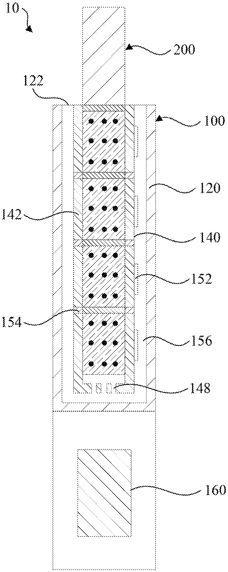
[0009] FIG. 1 is a schematic view of a smoking system according to an embodiment;
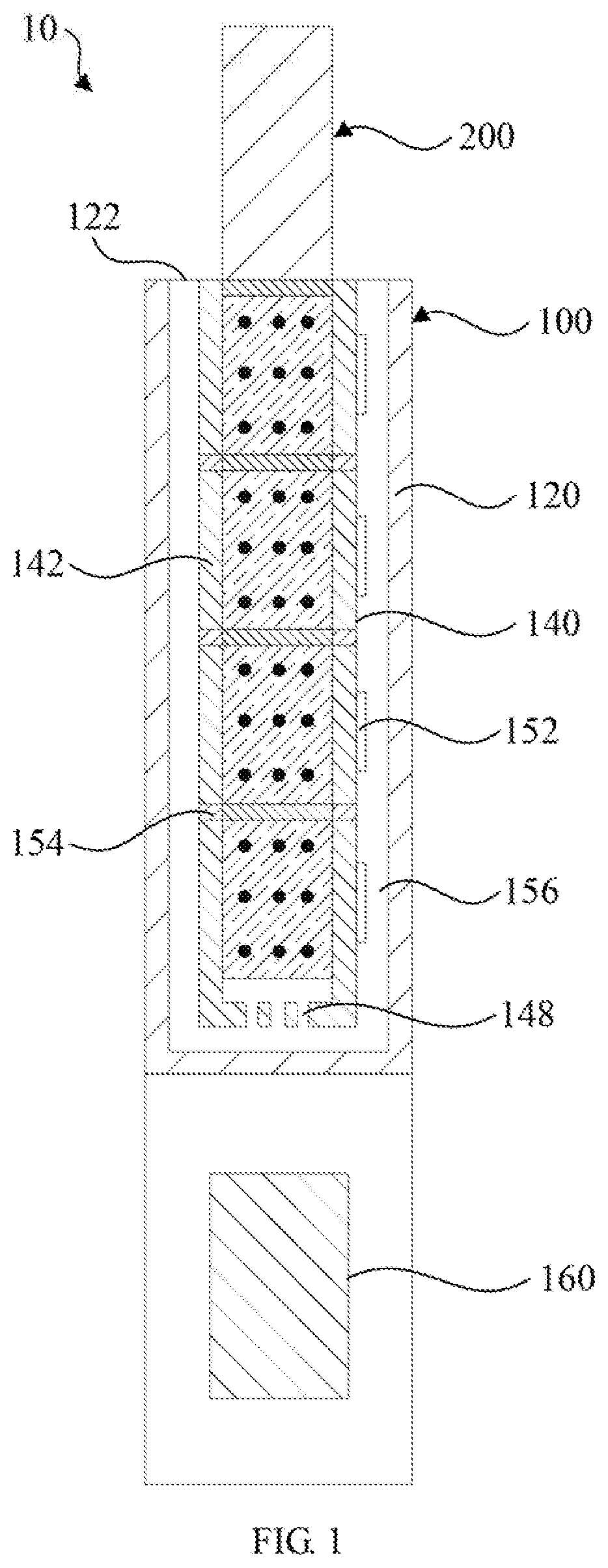
[0010] FIG. 2 is a schematic view of a smoking device in the smoking system of FIG. 1;
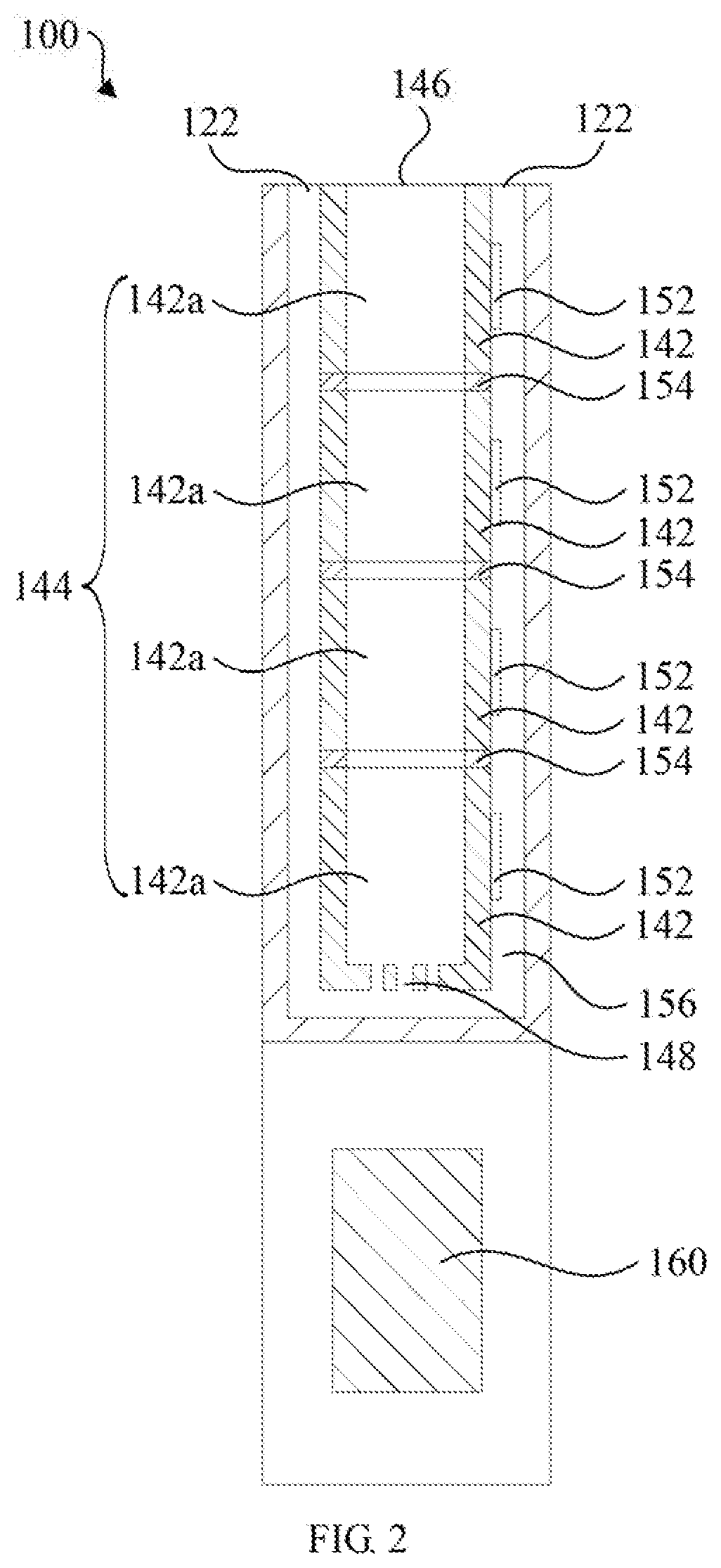
[0011] FIG. 3 is a schematic view of a smoking article in the smoking system of FIG. 1;
[0012] FIG. 4 is a schematic view of a smoking article of another embodiment of the smoking system of FIG. 1; and
[0013] FIG. 5 is a schematic view of a receptacle and a phase change material in the smoking system of FIG. 1.
DETAILED DESCRIPTION OF THE EMBODIMENTS
[0014] Embodiments of the invention are described more fully hereinafter with reference to the accompanying drawings. The various embodiments of the invention may, however, be embodied in many different forms and should not be construed as limited to the embodiments set forth herein. Rather, these embodiments are provided so that this disclosure will be thorough and complete, and will fully convey the scope of the invention to those skilled in the art. Elements that are identified using the same or similar reference characters refer to the same or similar elements.
[0015] Unless otherwise defined, all terms (including technical and scientific terms) used herein have the same meaning as commonly understood by one of ordinary skill in the art to which this invention belongs. The terms used herein is for the purpose of describing particular embodiments only and is not intended to limit the present disclosure. As used herein, the term "and/or" includes any and all combinations of one or more of the associated listed items,
[0016] Referring to FIG. 1, a smoking system 10 according to an embodiment includes a smoking device 100 and a smoking article 200. The smoking device 100 is used to heat the smoking article 200. The smoking device 100 heats the smoking article 200 within a certain temperature range and controls the smoking article 200 to be non-combusting, so that the nicotine and part of the tobacco flavor constituent can be transferred to the smoke for smoking, which can greatly reduce the released amount of tar and harmful constituents.
[0017] Referring also to FIG. 2, the smoking device 100 includes a housing 120 and a heating pot 140. The housing 120 is provided with a receiving chamber and an air inlet 122 in communication with the receiving chamber. The heating pot 140 is disposed in the receiving chamber. The heating pot 140 includes a plurality of heating elements 142 that are sequentially connected. In one embodiment, the heating element 142 can be a ceramic structure provided with a heating circuit. There may be 2 to 15 heating elements 142. Each of the heating elements 142 is provided with a heating chamber 142a, and the heating chambers 142a of the plurality of heating elements 142 form an accommodating chamber 144 for accommodating the smoking article 200. Both ends of the accommodating chamber 144 are provided with an insertion opening 146 for inserting the smoking article 200 and an air inlet hole 148 in communication with the air inlet 122, respectively. The plurality of heating elements 142 independently control temperature and sequentially heat the smoking article 200 in a direction from the insertion opening 146 towards the air inlet hole 148.
[0018] Referring also to FIG. 3, the smoking article 200 includes a mouthpiece 240 and a cigarette rod 220. In one embodiment, the mouthpiece 240 may be a filter. One end of the cigarette rod 220 is connected to the mouthpiece 240. The cigarette rod 220 includes a plurality of tobacco segments 242 that are sequentially connected. The tobacco segment 242 includes a tobacco material 244 and a phase change material 246 disposed in the tobacco material 244. The cigarette rod 220 can be inserted into the accommodating chamber 144, and the plurality of tobacco segments 242 are in one-to-one correspondence with the plurality of heating elements 142.
[0019] The plurality of tobacco segments 242 of the smoking article 200, in cooperation with the heating pot 140 having the plurality of heating elements 142 independently controlling temperature, facilitates controlling the temperature of the different tobacco segments 242. Since the plurality of heating elements 142 independently control the temperature and sequentially heat from the insertion opening 146 towards the air inlet hole 148, the plurality of tobacco segments 242 of the smoking article 200 may be sequentially heated in a direction from one end adjacent to the mouthpiece 240 towards the other end away from the mouthpiece 240. The high-concentration aerosol produced during the overall heating is avoided, and the released amount of smoke during the smoking process is relatively uniform, thereby balancing the sensory difference between the different number of suctions and improving the consistency of the smoke taste. Since the phase change material 246 absorbs or releases a large amount of heat during a phase change process, it is possible to delay the heating and cooling and prevent the temperature from increasing or decreasing too fast, thereby better controlling the temperature of the smoking article 200.
[0020] In addition, if the heating sequence of the heating pot 140 to the smoking article 200 is reversed from that of the present embodiment, that is, the smoking article 200 is sequentially heated in a direction from the smoking article 200 towards the mouthpiece 240, since the gas stream flowing through the heated tobacco segment 242 has a higher temperature, the gas stream heats the tobacco segment 242 that flows later, resulting in a part of the smoke constituent in the unheated tobacco segment 242 being sublimated or the smoke constituent having a lower decomposition temperature being released. Therefore, the part of the smoke constituent in the tobacco segment 242 heated later is passed away in advance, resulting in inconsistent smoke taste when the different tobacco segments 242 are heated. Moreover, heating the unheated portion of the cigarette too early may result in the veneration of a part of smoke or the thermal degradation of the portion of the cigarette due to heat, thereby changing its own quality. Reheating the previously heated portion may result in an unpleasant odor or harmful constituent. In the present embodiment, in a manner from one end adjacent to the mouthpiece 240 towards the other end away from the mouthpiece 240, the heated gas stream can be prevented from flowing through the unheated tobacco segment 242, thereby avoiding the aforementioned problems of inconsistencies in the smoke taste and causing unpleasant odor or harmful constituents.
[0021] In one of the embodiments, the smoking article 200 further includes a heat insulation layer 260 located between two adjacent tobacco segments 242 to avoid heat conduction and interaction between the tobacco segments 242. In addition, in one embodiment, the heat insulation layer 260 may also be located between the mouthpiece 240 and the tobacco segment 242 connected to the mouthpiece 240 to prevent heat from being conducted to the mouthpiece 240. Referring also to FIG. 4, in another embodiment, the adjacent tobacco segments 242 may be directly connected without providing the heat insulation layer 260, which can also achieve the effect of increasing the consistency of the smoke taste and prevent the temperature from increasing or decreasing too fast.
[0022] The phase change material 246 includes a solid-solid phase change material and a solid-liquid phase change material, and the phase change material 246 has a phase change temperature of 200.degree. C. to 500.degree. C., preferably 240.degree. C. to 350C. Regarding the solid-liquid phase change materials, in order to prevent the phase change material 246 from being drawn into the oral cavity after melting, and referring also to FIG. 5, in one embodiment, the smoking article 200 may further include a receptacle 280 for accommodating the phase change material 246. The phase change material 246 is located in the receptacle 280. In addition, the receptacle 280 is made of a heat conductive material having a melting point generally greater than or equal to 500.degree. C. The melting point of the receptacle 280 needs to be higher than the heating temperature of the heating element 142. The heating temperature of the heating element 142 generally ranges front 200.degree. C. to 500.degree. C. The nicotine and most tobacco flavoring constituents can be transferred to the smoke at a temperature of 200.degree. C. to 500.degree. C., and excessive temperatures can easily produce harmful gases or ignite the smoking article 200. Moreover, in one embodiment, the heating temperature of the heating element 142 generally ranges from 200.degree. C. to 350.degree. C. The lower temperature control, on the one hand, facilitates safe control and avoids scalding. On the other hand, nicotine and tobacco flavoring constituents can be released at a relatively smooth rate, and the taste of smoking is better.
[0023] In one embodiment, the receptacle 280 is made of aluminum foil. The receptacle 280 has good heat conductivity to facilitate heat homogenization within the tobacco segment 242. The shape of the receptacle 280 may be similar to a capsule, and the phase change material 246 is enclosed in the receptacle 280. In one embodiment, there are a plurality of receptacles 280, and the plurality of receptacles 280 are uniformly distributed in the tobacco material 244 of each of the tobacco segments 242, which is more advantageous for heat homogenization within the tobacco segment 242.
[0024] The phase change material 246 may be in a form of particle, filament, or the like. In one embodiment, the phase change material 246 has a solid-liquid phase change temperature of 200.degree. C. to 500.degree. C. When the heating element 142 heats the phase change material 246 to the solid-liquid phase change temperature, the phase change material 246 melts, and the phase change material 246 absorbs a large amount of heat during the phase change process, thereby preventing the temperature from increasing too fast. When the temperature of the phase change material 246 is less than the solid-liquid phase change temperature, the phase change material 246 solidifies, and the phase change material 246 releases a large amount of heat during the phase change process, thereby preventing the temperature from decreasing too fast. In one embodiment, the phase change temperature of the phase change material 246 may also be selected between 240.degree. C. to 350.degree. C. For example, the phase change material 246 may be, for example, sodium nitrate NaNO.sub.3.
[0025] In one of the embodiments, constituents of the tobacco materials 244 in the plurality of tobacco segments 242 are different. The constituent of each of the tobacco segments 242 may be adjusted as desired to provide a better taste. For example, different tobacco segments 242 employ different types of tobacco materials 244 to change the taste and flavor during the smoking process, thereby enriching the smoking experience. In one embodiment, a proportion of a tobacco constituent contained in the tobacco material 244 in the plurality of tobacco segments 242 capable of producing a smoke constituent having a lower decomposition temperature gradually decreases in a direction from one end of the cigarette rod 220 adjacent to the mouthpiece 240 towards the other end thereof away from the mouthpiece 240. Since the smoke produced from the tobacco segment 242 away from the mouthpiece 240 flows through the tobacco segment 242 adjacent to the mouthpiece 240, although the tobacco segment 242 adjacent to the mouthpiece 240 has already released the smoke, a small amount of low-temperature decomposition smoke is still released when a subsequent smoke with a certain amount of heat enters. Therefore, the proportion of the constituent gradually decrease in a direction from one end adjacent to the mouthpiece 240 towards the other end away from the mouthpiece 240, which is more conducive to improving the consistency of the smoke taste.
[0026] Referring again to FIGS. 1 and 2, in one of the embodiments, the smoking device 100 generally further includes a power supply assembly 160 that supplies power to the heating pot 140, which may be connected to the housing 120 outside the housing 120. In other embodiments, the power supply assembly 160 may also be located inside the housing 120. Alternatively, the smoking device 100 itself does not have the power supply assembly 160, and the smoking device 100 is detachably connected to the external power supply assembly 160 to supply power to the heating pot 140.
[0027] In order to more accurately control and monitor the temperature of the heating pot 140, in one of the embodiments, the heating pot 140 further includes a plurality of temperature sensors 152. At least one temperature sensor 152 is disposed on each of the heating elements 142. In one embodiment, the heating pot 140 also includes a heat insulation washer 154 located between the adjacent heating elements 142 to avoid heat conduction and interaction between the heating elements 142.
[0028] In one embodiment, the smoking device 100 may further include a controller disposed in the receiving chamber to control the independent power supply to the plurality of heating elements 142. The temperature sensor 152 may be communicatively coupled to the controller, and the controller may control the power supply to the heating element 142 in accordance with the temperature measured by the temperature sensor 152 to more accurately adjust the temperature of the heating element 142.
[0029] In one of the embodiments, a preheating passage 156 is formed between an inner wall of the housing 120 and an outer wall of the heating pot 140. One end of the preheating passage 156 is in communication with the air inlet 122, and the other end thereof is in communication with the air inlet hole 148. When using the smoking article 200, the external air enters the preheating passage 156 through the air inlet 122, is preheated by the outer wall of the heating pot 140, and enters the accommodating chamber 144 through the air inlet hole 148 to enter the smoking article 200. The preheating passage 156 is designed so that, on the one hand, the temperature of the outer wall of the heating pot 140 can be reduced, thereby reducing the temperature of the housing 120 and preventing scalding, on the other hand, the heat of the heating pot 140 can be efficiently utilized to avoid energy waste.
[0030] In one embodiment, the housing 120 has a circular tubular shape, and the heating element 142 can also have a circular tubular shape. The smoking article 200 may be heated more uniformly, and the air inlet 122 and the insertion opening 146 both located at an opening at one end of the housing 120. In addition, in an embodiment in Which the smoking device 100 is provided with the power supply assembly 160, the power supply assembly 160 may be located at the other end of the housing 120, and the overall arrangement is more reasonable and convenient for holding and using.
[0031] Although the respective embodiments have been described one by one, it shall be appreciated that the respective embodiments will not be isolated. Those skilled in the art can apparently appreciate upon reading the disclosure of this application that the respective technical features involved in the respective embodiments can be combined arbitrarily between the respective embodiments as long as they have no collision with each other. Of course, the respective technical features mentioned in the same embodiment can also be combined arbitrarily as long as they have no collision with each other.
[0032] Although the invention is illustrated and described herein with reference to specific embodiments, the invention is not intended to be limited to the details shown. Rather, various modifications may be made in the details within the scope and range of equivalents of the claims and without departing from the invention.
* * * * *
D00000
D00001
D00002
D00003
D00004
D00005
XML
uspto.report is an independent third-party trademark research tool that is not affiliated, endorsed, or sponsored by the United States Patent and Trademark Office (USPTO) or any other governmental organization. The information provided by uspto.report is based on publicly available data at the time of writing and is intended for informational purposes only.
While we strive to provide accurate and up-to-date information, we do not guarantee the accuracy, completeness, reliability, or suitability of the information displayed on this site. The use of this site is at your own risk. Any reliance you place on such information is therefore strictly at your own risk.
All official trademark data, including owner information, should be verified by visiting the official USPTO website at www.uspto.gov. This site is not intended to replace professional legal advice and should not be used as a substitute for consulting with a legal professional who is knowledgeable about trademark law.