Limb Assembly For Sport Bow
Liu; Chi-Chang
U.S. patent application number 16/131011 was filed with the patent office on 2020-03-19 for limb assembly for sport bow. The applicant listed for this patent is Chi-Chang Liu. Invention is credited to Chi-Chang Liu.
| Application Number | 20200088492 16/131011 |
| Document ID | / |
| Family ID | 69773904 |
| Filed Date | 2020-03-19 |


| United States Patent Application | 20200088492 |
| Kind Code | A1 |
| Liu; Chi-Chang | March 19, 2020 |
LIMB ASSEMBLY FOR SPORT BOW
Abstract
A limb assembly for a sport bow includes two limb pockets connected to two rises of the bow and each limb pockets includes two slots with a separation plate connected between the two slots. Each slot includes an open space. Two limb units each have the first end thereof inserted into the slots from the open space of each of the two limb pockets. A string IS connected between two respective second ends of the two limb units. Two resilient members are respectively located between the body and each of the two limb units. Each resilient member has a buffering portion protruding therefrom which is received in a recess of the rise corresponding thereto so that each limb unit resiliently compresses the rise by the resilient members. The resilient members are replaceable to adjust the compress force between the limb units and the rises.
| Inventors: | Liu; Chi-Chang; (TAICHUNG CITY, TW) | ||||||||||
| Applicant: |
|
||||||||||
|---|---|---|---|---|---|---|---|---|---|---|---|
| Family ID: | 69773904 | ||||||||||
| Appl. No.: | 16/131011 | ||||||||||
| Filed: | September 13, 2018 |
| Current U.S. Class: | 1/1 |
| Current CPC Class: | F41B 5/1403 20130101; F41B 5/10 20130101 |
| International Class: | F41B 5/14 20060101 F41B005/14; F41B 5/10 20060101 F41B005/10 |
Claims
1. A limb assembly for a sport bow, comprising: a body having two rises on two ends thereof, each of the two rises having a recess; two limb pockets connected to the two rises and each having two slots defined therein, a separation plate connected between the two slots of each of the two limb pockets, each of the slots including an open space, a bolt extending through the separation plate and connecting each of the two limb pockets to the body; two limb units each having a first end thereof inserted into the slots from the open space of each of the two limb pockets, a string connected between two respective second ends of the two limb units, and two resilient members respectively located between the body and each of the two limb units, each resilient member having a buffering portion protruding therefrom which is received in the recess of the rise corresponding thereto, each of the limb units resiliently compressing the rise corresponding thereto by the resilient members.
2. The limb assembly as claimed in claim 1, wherein each of the rises includes a connection portion and two pivotal members, the two pivotal members are located on two sides of the connection portion, the connection portion includes two first recessed portions respectively defined in the two sides thereof, each pivotal member has a second recessed portion that faces the first recessed portion, each pivotal member having the recess of the rise and the recess located opposite to the second recessed portion, the buffering portion of each resilient member received in the recess of the pivotal member corresponding thereto, an axle extends through the two pivotal members and the connection portion, two bolts respectively threadedly connected to two ends of the axle, each bolt contacts against an outside face of the pivotal member corresponding thereto to secure the two pivotal members to the connection portion.
3. The limb assembly as claimed in claim 2, wherein the open space of each slot includes a long opening and a short opening, the long opening faces the rise, the short opening is located at an end of the slot.
4. The limb assembly as claimed in claim 3, wherein each of the limb units includes two sub-limbs which are respectively inserted into the slots via the two short openings.
5. The limb assembly as claimed in claim 4, wherein the buffering portion of each resilient member has a hole defined therethrough so as to provide flexibility to the buffering portion.
6. The limb assembly as claimed in claim 5, wherein an elastic coefficient of each of the resilient members is larger than or equal to 100 GPa.
7. The limb assembly as claimed in claim 6, wherein each of the resilient members is made of rubber, low density polyethylene, polypropylene, polyethylene terephthalate, polystyrene, nylon, oak or carbon fiber reinforcement plastic.
Description
BACKGROUND OF THE INVENTION
1. Fields of the Invention
[0001] The present invention relates to a limb assembly, and more particularly, to a limb assembly of a sport bow and the limb assembly allows the users to easily change suitable limbs.
2. Descriptions of Related Art
[0002] The conventional sport bow generally includes a body having a grip located at the central portion thereof, and with two rises extend from two ends of the body. Each raise is connected with a limb which is connected with a cam, and a string is connected between the two cams. A user draws the string to store energy which is used to shoot the arrow when releasing the string. However, the draw weight is different of different sport bows, and some users may not able to draw the string to a full draw due to the draw weight is not suitable for the users. Therefore, the users should use a specific sport bow that is suitable for the user to operate. Nevertheless, not every user can own his or her sport bow, in order to obtain a proper sport bow, the limbs need to be replaced.
[0003] The replacement of the limbs requires a lot of time and needs specific tools for a skilled person, and this job cannot be easily done by a general user. Therefore, a replaceable limb assembly is developed to improve the problem mentioned above.
[0004] The present invention is intended to provide a limb assembly that is easily installed to the sport bow to meet different users' needs.
SUMMARY OF THE INVENTION
[0005] The present invention relates to a limb assembly for a sport bow, and comprises a body having two raise on two ends thereof and each rise has a recess. Two limb pockets are connected to the two rises and each have two slots with a separation plate connected therebetween. Each of the slots includes an open space. Two limb units each have the first end thereof inserted into the slots from the open space of each of the two limb pockets. A string is connected between two respective second ends of the two limb units. Two resilient members are respectively located between the body and each of the two limb units. Each resilient member has a buffering portion protruding therefrom which is received in the recess of the rise corresponding thereto. Each of the limb units resiliently compress the rise corresponding thereto by the resilient members.
[0006] Preferably, each of the rises includes a connection portion and two pivotal members. The two pivotal members are located on two sides of the connection portion. The connection portion includes two first recessed portions respectively defined in the two sides thereof. Each pivotal member has a second recessed portion that faces the first recessed portion. An axle extends through the two pivotal members and the connection portion. Two bolts are respectively threadedly connected to two ends of the axle. Each bolt contacts against the outside face of the pivotal member corresponding thereto to secure the two pivotal members to the connection portion.
[0007] Preferably, the open space of each slot includes a long opening and a short opening. The long opening faces the rise, and the short opening is located at one end of the slot.
[0008] Preferably, each of the limb units includes two sub-limbs which are respectively inserted into the slots via the two short openings.
[0009] Preferably, the buffering portion of each resilient member has a hole defined therethrough so as to provide flexibility to the buffering portion.
[0010] Preferably, the elastic coefficient of each of the resilient members 7 is larger than or equal to 100 GPa.
[0011] Preferably, each of the resilient members 7 is made of rubber, low density polyethylene, polypropylene, polyethylene terephthalate, polystyrene, nylon, oak or carbon fiber reinforcement plastic.
[0012] The advantages of the present invention are that the users may change the resilient members to adjust the force that the limb units compress the rises, without changing the limbs, to obtain a suitable drawing force.
[0013] The present invention will become more obvious from the following description when taken in connection with the accompanying drawings which show, for purposes of illustration only, a preferred embodiment in accordance with the present invention.
BRIEF DESCRIPTION OF THE DRAWINGS
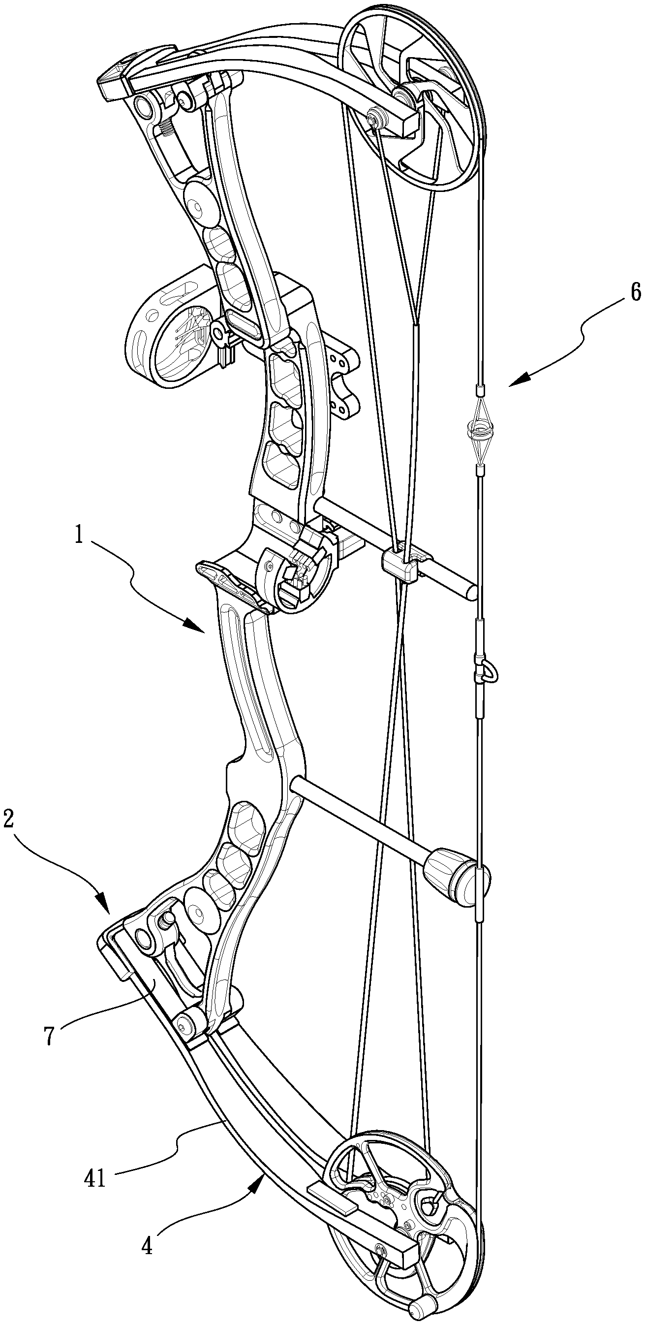
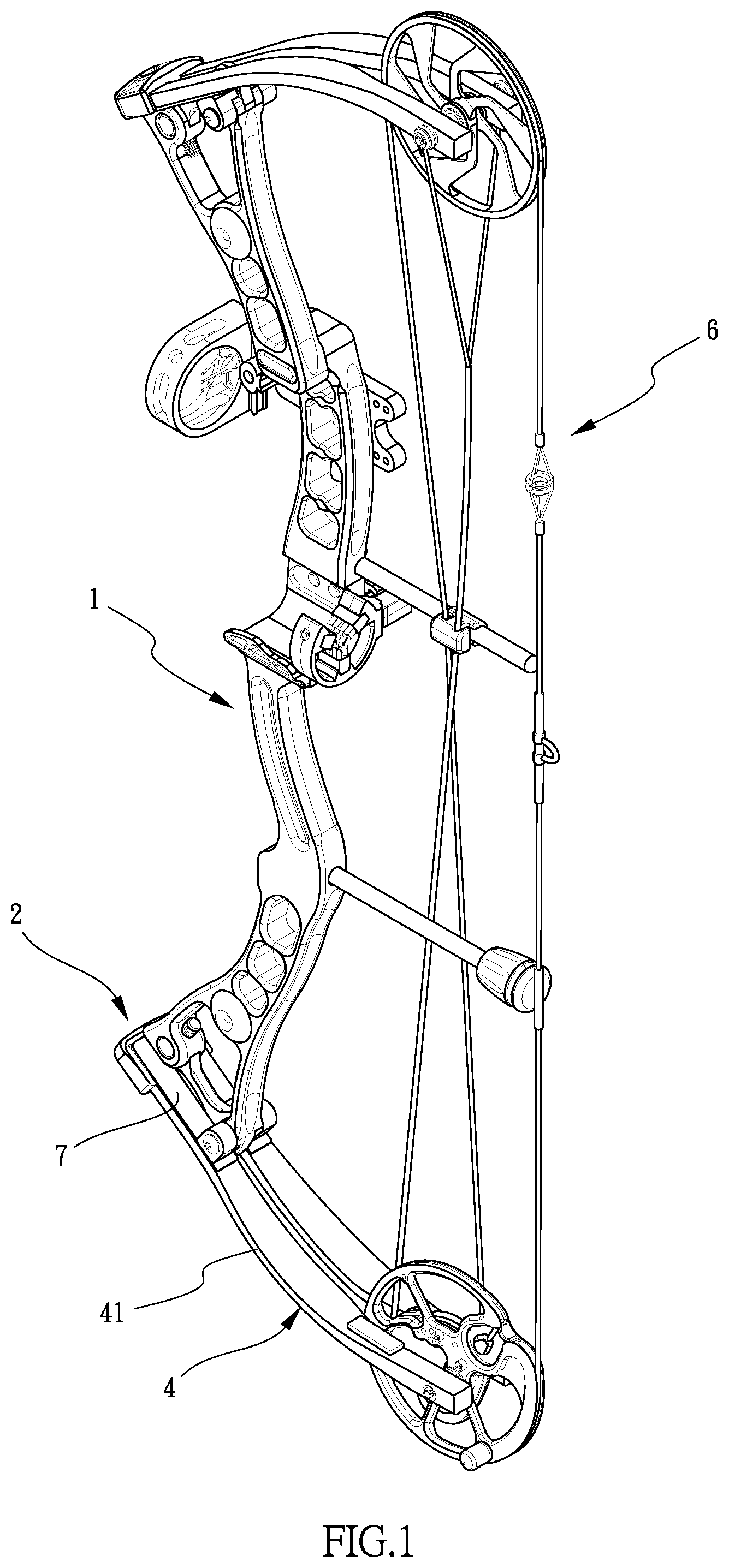
[0014] FIG. 1 is a perspective view to show the sport bow with the limb assemblies of the present invention;
[0015] FIG. 2 is an enlarged view to show the assembly of the rise, the limb pocket and the resilient members of the limb assemblies of the present invention;
[0016] FIG. 3 is an exploded view of the disclosure in FIG. 3;
[0017] FIG. 4 is an cross sectional view, taken along line IV-IV of FIG. 2;
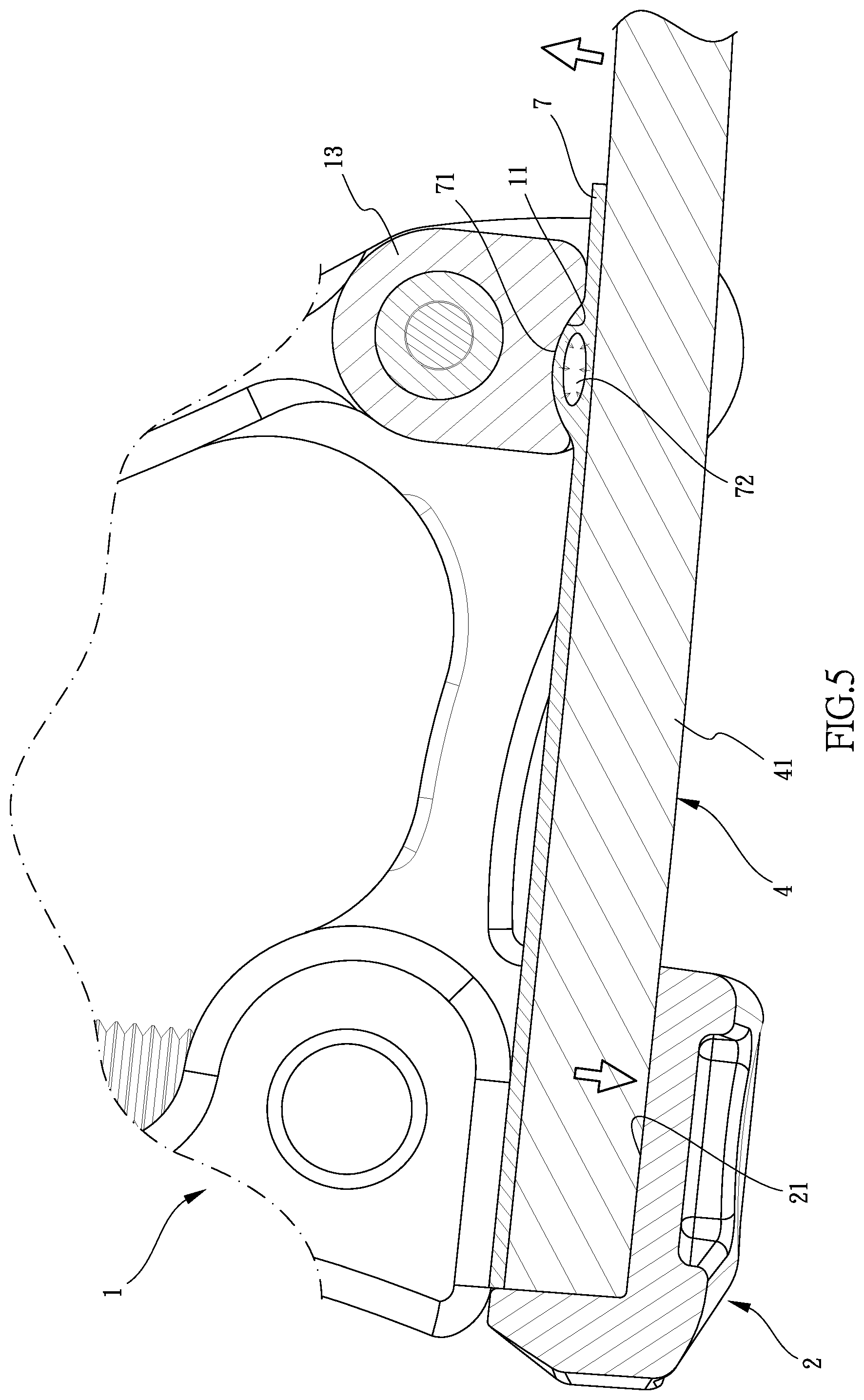
[0018] FIG. 5 shows the limb compresses the resilient members when drawing the string, and
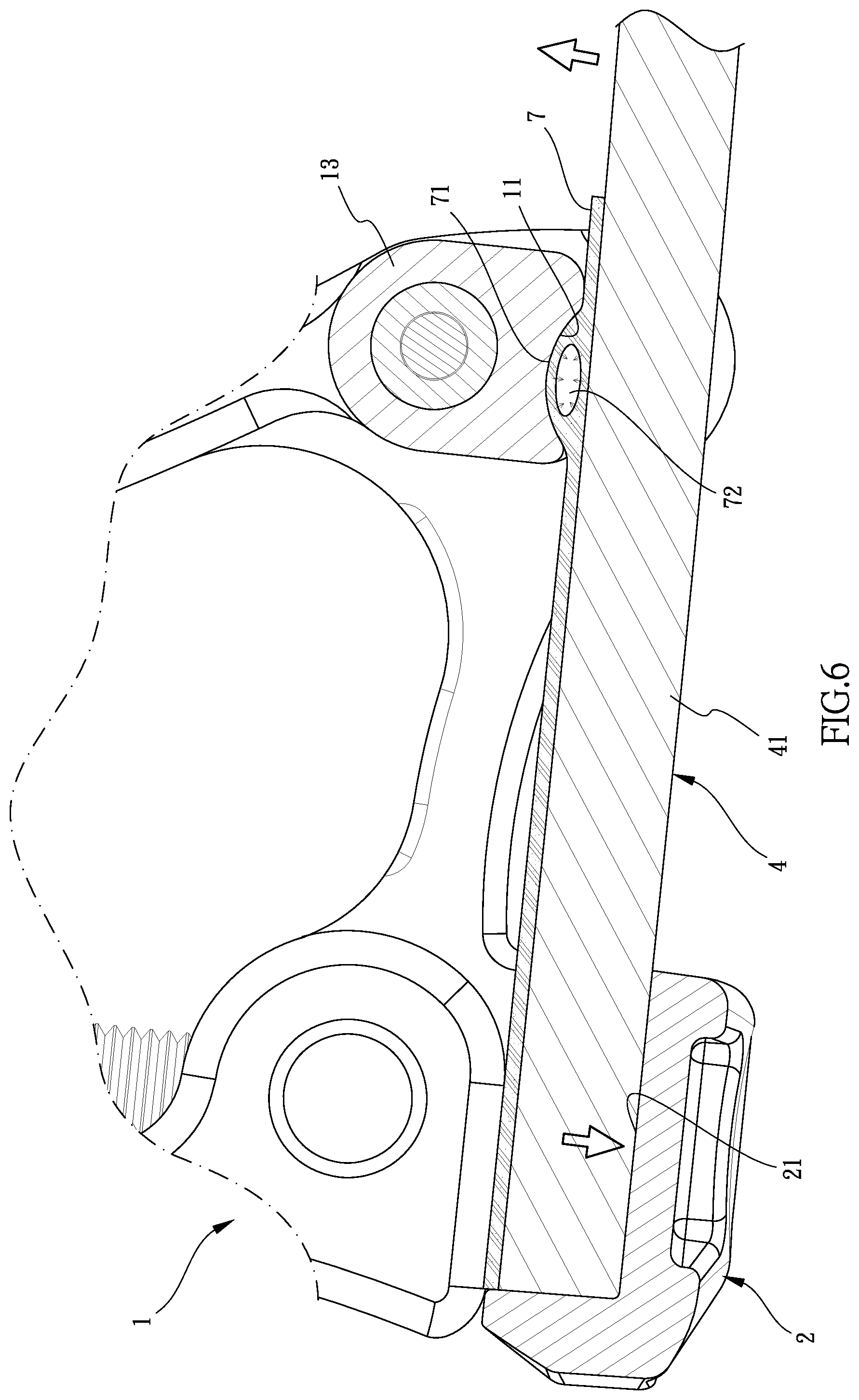
[0019] FIG. 6 shows the operation of the resilient member made of different material.
DETAILED DESCRIPTION OF THE PREFERRED EMBODIMENT
[0020] Referring to FIGS. 1 to 6, the limb assembly for a sport bow of the present invention comprises a body 1 having two raise 10 connected two ends thereof. Two limb pockets 2 are respectively connected to the two rises 1 and each limb unit 4 has two slots 21 defined therein. A separation plate 23 is connected between the two slots 21 of each of the two limb pockets 2. Each of the slots 21 includes an open space 22, wherein the open space 22 includes a long opening 221 and a short opening 222. The long opening 221 faces the rise 10, and the short opening 222 is located at an end of the slot 21 and communicates with the long opening 221. A bolt 3 extends through the separation plate 23 and connects each of the two limb pockets 2 to the body 1. Each of the rises 10 includes a connection portion 12 and two pivotal members 13. The two pivotal members 13 are located on two sides of the connection portion 12. The connection portion 12 includes two first recessed portions 121 respectively defined in the two sides thereof. Each pivotal member 13 has a second recessed portion 131 that faces the first recessed portion 121, and a recess 11 that is located opposite to the second recessed portion 131 as shown in FIG. 3. An axle 5 extends through the two pivotal members 13 and the connection portion 12, and two bolts 8 are respectively threadedly connected to two ends of the axle 5. Each bolt 8 contacts against the outside face of the pivotal member 13 corresponding thereto to secure the two pivotal members 13 to the connection portion 12.
[0021] Two limb units 4 each have the first end thereof inserted into the slots 21 from the open space 22 of each of the two limb pockets 2. A string 6 is connected between two cams that are respectively connected to the second ends of the two limb units 4. Specifically, each of the limb units 4 includes two sub-limbs 41 which are respectively inserted into the slots 21 via the two short openings 222.
[0022] Two resilient members 7 are respectively located between the body 1 and each of the two limb units 4. Each resilient member 7 has a buffering portion 71 protruding therefrom. The buffering portion 71 of each resilient member 7 is received in the recess 11 of the pivotal member 13 corresponding thereto. Each of the limb units 4 resiliently compresses the rise 10 corresponding thereto by the resilient members 7. The buffering portion 71 of each resilient member 7 has a hole 72 defined therethrough so as to provide flexibility to the buffering portion 71. The elastic coefficient of each of the resilient members 7 is larger than or equal to 100 GPa. Each of the resilient members 7 is made of rubber, low density polyethylene, polypropylene, polyethylene terephthalate, polystyrene, nylon, oak or carbon fiber reinforcement plastic.
[0023] As shown in FIGS. 4 to 6, when the user draws the string 6, the limb units 4 compress the resilient members 7. If a user cannot draw the string 6 to a full draw, this means the limb units 4 are too stiff for the user, the user then can change the resilient members 7 that have higher elastic coefficient. The resilient members 7 also prevent the limb units 4 to hit the limb pockets 2 when the limb units 4 bounce back.
[0024] Furthermore, the hole 72 in each buffering portion 71 provides proper flexibility to the buffering portion 71 such that the noise caused by the string 6 and the deformation of the limb units 4 can be reduced.
[0025] The replacement of the resilient members 7 are easy, and the whole limb units 4 and the limb pockets 2 do not need to be dis-assembled. By choosing correct resilient members 7, the sport bow can be used by different users.
[0026] While we have shown and described the embodiment in accordance with the present invention, it should be clear to those skilled in the art that further embodiments may be made without departing from the scope of the present invention.
* * * * *
D00000
D00001
D00002
D00003
D00004
D00005
D00006
XML
uspto.report is an independent third-party trademark research tool that is not affiliated, endorsed, or sponsored by the United States Patent and Trademark Office (USPTO) or any other governmental organization. The information provided by uspto.report is based on publicly available data at the time of writing and is intended for informational purposes only.
While we strive to provide accurate and up-to-date information, we do not guarantee the accuracy, completeness, reliability, or suitability of the information displayed on this site. The use of this site is at your own risk. Any reliance you place on such information is therefore strictly at your own risk.
All official trademark data, including owner information, should be verified by visiting the official USPTO website at www.uspto.gov. This site is not intended to replace professional legal advice and should not be used as a substitute for consulting with a legal professional who is knowledgeable about trademark law.