Thermo Efficiency Measurement System
Subbloie; Albert ; et al.
U.S. patent application number 16/574944 was filed with the patent office on 2020-03-19 for thermo efficiency measurement system. The applicant listed for this patent is Budderfly, Inc.. Invention is credited to Kenneth Buda, Jaan Leemet, Albert Subbloie, Mark Alphonse Veikos.
| Application Number | 20200088433 16/574944 |
| Document ID | / |
| Family ID | 69773826 |
| Filed Date | 2020-03-19 |


| United States Patent Application | 20200088433 |
| Kind Code | A1 |
| Subbloie; Albert ; et al. | March 19, 2020 |
Thermo Efficiency Measurement System
Abstract
Systems and methods are provided for determining an energy transfer rate of a room via one or more sensors to determine a baseline efficiency measurement of a room as well as delta efficiency gains obtained by making changes to internal or external factors affecting thermal efficiency. The system further include the automatic control for various equipment associated with the room and automatic measurement based on the status of the room.
| Inventors: | Subbloie; Albert; (Orange, CT) ; Buda; Kenneth; (Scarsdale, NY) ; Leemet; Jaan; (Aventura, FL) ; Veikos; Mark Alphonse; (Trumbull, CT) | ||||||||||
| Applicant: |
|
||||||||||
|---|---|---|---|---|---|---|---|---|---|---|---|
| Family ID: | 69773826 | ||||||||||
| Appl. No.: | 16/574944 | ||||||||||
| Filed: | September 18, 2019 |
Related U.S. Patent Documents
| Application Number | Filing Date | Patent Number | ||
|---|---|---|---|---|
| 62732786 | Sep 18, 2018 | |||
| Current U.S. Class: | 1/1 |
| Current CPC Class: | F24F 2110/10 20180101; F24F 11/63 20180101; F24F 2110/32 20180101; F24F 11/46 20180101; F24F 2110/20 20180101; F24F 2130/20 20180101; F24F 2110/12 20180101; F24F 2120/10 20180101 |
| International Class: | F24F 11/46 20060101 F24F011/46; F24F 11/63 20060101 F24F011/63 |
Claims
1. A system for determining an energy transfer rate of a room comprising: a first sensor mounted in a first housing, the first sensor generating first environmental data and including: a first environmental measuring device, a first power source, a first processor, a first storage, and a first communications hardware coupled to a network; a mounting element connected to the housing such that said first sensor is freely positionable within the room; software executing on said first processor and generating first environmental data corresponding to discrete environmental measurements taken within the room at first time intervals and including time data associated with each discrete environmental measurement; a computer coupled to the network and having a computer storage accessible by said computer, said storage having threshold environmental data saved thereon; wherein a second sensor positioned outside the room generates second environmental data corresponding to environmental measurements taken outside the room and including time data associated with the environmental measurements; the first environmental data and the second environmental data transmitted to said computer via the network; software executing on said computer processing the first environmental data and the second environmental data compared to the threshold environmental data to generate an energy transfer rate of the room.
2. The system of claim 1 wherein the first environmental data is selected from the group consisting of: temperature, humidity and combinations thereof.
3. The system of claim 2 wherein the second environmental data is selected from the group consisting of: temperature, humidity, wind speed, wind direction, solar energy intensity, and combinations thereof.
4. The system of claim 3 wherein when the first and second environmental data each comprise temperature measurements and the second environmental data comprises an outside air temperature, the temperature measurements taken by the first sensor at the first time intervals are compared to the temperature measurements taken by the second sensor to calculate a temperature differential.
5. The system of claim 1 wherein at least two sensors are positioned in the room and the energy transfer rate determination further indicates efficiency of one or more portions of the room.
6. The system according to claim 1 wherein a volume of the room is considered in the energy transfer rate determination.
7. The system according to claim 1 wherein a surface area of internal surfaces of the room is considered in the energy transfer rate determination.
8. The system according to claim 1 wherein a date and a geographic location of the room is considered in the energy transfer rate determination.
9. The system according to claim 8 wherein when the room is located in a facility, the location of the room within the facility is considered in the energy transfer rate determination.
10. The system according to claim 1 wherein said computer automatically initiates the discrete environmental measurements of said first sensor based on input relating to the status of the room.
11. The system according to claim 10 wherein an occupancy sensor located in the room provides data to said computer which is used to determine the status of the room.
12. The system according to claim 10 wherein said computer automatically controls various equipment associated with the room prior to initiating the discrete environmental measurements of said first sensor.
13. The system according to claim 14 wherein the various equipment is selected from the group consisting of: motorized window shades or binds, motorized air vents associated with the room, HVAC equipment servicing the room and combinations thereof.
14. The system according to claim 1 further comprising a remote computer coupled to the network and in communication with said computer, said remote computer receiving the first environmental data and the second environmental data.
15. A system for determining an energy transfer rate of a room comprising: a sensor mounted in a housing, the sensor generating environmental data and including: a environmental measuring device, a power source, a processor, a storage, and a communications hardware coupled to a network; a mounting element connected to the housing such that said sensor is freely positionable within the room; a computer coupled to the network and having a computer storage accessible by said computer, said storage having threshold environmental data saved thereon; software executing on said processor and generating environmental data corresponding to a discrete environmental measurement taken within the room and including time data associated with the discrete environmental measurement; software executing on said computer for automatically initiating the discrete environmental measurement during based on input relating to the status of the room; the environmental data transmitted to said computer via the network; said software executing on said computer processing the environmental data compared to the threshold environmental data to generate an energy transfer rate of the room.
16. The system according to claim 15 wherein an occupancy sensor located in the room provides data to said computer which is used to determine the status of the room or to send alerts or combinations thereof.
17. The system according to claim 15 wherein at least one window or door sensor is located in the room provides data to said computer which is used to determine the status of the room.
18. The system according to claim 15 wherein said computer receives data relating to whether a user is active on a computer associated with the room and the data is used to determine the status of the room.
19. The system according to claim 15 wherein said computer automatically controls various equipment associated with the room prior to initiating the discrete environmental measurement.
20. The system according to claim 19 wherein the various equipment is selected from the group consisting of: motorized window shades or binds, motorized air vents associated with the room, HVAC equipment servicing the room and combinations thereof.
21. The system according to claim 15 further comprising a second sensor mounted outside the room and generating second environmental data corresponding to environmental measurements taken outside the room.
22. The system according to claim 21 wherein said first sensor is selected from the group consisting of: temperature sensor, humidity sensor and combinations thereof.
23. The system according to claim 21 wherein said second sensor measures temperature, humidity, wind speed, solar intensity or combinations thereof.
24. The system according to claim 15 wherein the initiation of the discrete environmental measurement is coordinated with a schedule of the set points for HVAC equipment serving the room.
25. The system according to claim 15 wherein the threshold environmental data comprises historical data associated with the room or with a facility within which the room is located.
26. The system according to claim 15 wherein the threshold environmental data comprises calculated energy transfer rates based on a configuration of the room or the construction materials of the room or a geographic location of the room or combinations thereof.
27. A method for determining an energy transfer rate of a room comprising the steps of: positioning a plurality of sensors within a plurality of different rooms in a facility; generating environmental data for a plurality of discrete environmental measurements in the plurality of rooms, each discrete environmental measurement including time data corresponding to a time when each of the environmental measurements was taken and which room the measurement corresponds to; transmitting the environmental data to a computer via a network connection; processing the environmental data based upon a rate of change of the environmental measurements over a set time period; determining an energy transfer indication of each of the rooms by comparing the environmental data with threshold environmental data.
28. The method of claim 27 wherein the computer automatically initiates the plurality of discrete environmental measurements based on input received by the computer relating to the status of the room.
29. The method of claim 27 wherein an occupancy sensor located in the room provides data to the computer which is used to determine the status of the room.
30. The method of claim 27 wherein the computer automatically controls various equipment associated with the room prior to initiating the discrete environmental measurements.
31. The method of claim 30 wherein the computer automatically shuts down HVAC equipment servicing the room or closes vents serving the room prior to initiating the discrete environmental measurements.
Description
FIELD OF THE INVENTION
[0001] The present invention relates to systems and methods for evaluating the thermal envelop of an individual space or room to determine the value of stepwise changes taken to improve the thermal envelop of the space. In particular, the system relates to a measurement device that can be freely placed in the space to gather specific environmental data that can be compared/combined with target or expected data or with alternative measurement data to achieve an energy reduction goal.
BACKGROUND OF THE INVENTION
[0002] Energy use has been a concern for companies for many years leading to many different efforts to quantify energy use with the purpose of determining how energy use could be reduced. For years it has been the escalating costs associated with excessive energy use that has driven the desire to lower energy usage. As energy costs continue to escalate, cost is still a driving factor motivating companies to look for new and better ways to reduced energy usage.
[0003] In recent years, in addition to excessive costs, concern for the impact that energy production puts on the environment has also provided a motivation for seeking to reduce energy usage. In particular, concerns relating to the burning of fossil fuels and the impact this may have on the planet has spurred efforts to look into the use of renewable energy sources. However, it has been observed that renewable energy sources are typically restricted in size in the ability to generate megawatt hours when compared to fossil fuel burning plants. So while renewable energy sources continue to be integrated into the power grid, the need for non-renewable (e.g., fossil fuel burning plants) energy sources continues in view of the high need for electrical energy. This is especially the case with heavy use of electronic and electrical devices in residential, commercial and even industrial applications. However, if the overall energy consumption could be reduced, then the reliance and need for non-renewable energy sources could likewise be reduced and maybe even eliminated.
[0004] U.S. Energy Information Administration (EIA) stated that primary energy consumption in the United States reached a record high of 101.3 quadrillion British thermal units (Btu) in 2018, up 4% from 2017 and 0.3% above the previous record set in 2007. The increase in 2018 was the largest increase in energy consumption, in both absolute and percentage terms, since 2010. https://www.eia.gov/todayinenergy/detail.php?id=39092. Environmental control takes up a large portion of the overall energy consumption on the power grid. EIA estimated that in 2018, electricity use for cooling the interior of buildings (space cooling) by the U.S. residential and commercial sectors was about 377 billion kilowatthours (kWh), which was equal to about 9% of total U.S. electricity consumption in 2018. See, https://www.eia.gov/tools/faqs/faq.php?id=1174$t=1. As such, energy consumption for environmental control is a large sector of the energy usage market that could be targeted for reduced energy usage.
[0005] A major factor in determining the amount of energy that is used for environmental control is the thermal envelop of a building or structure. The thermal envelop will define how easily energy is transferred to or from a space, which in turn, will determine how much energy is needed to maintain a space at a certain environmental level. For example, if a space has a very poor thermal envelop (i.e., allows energy to be easily transferred to or from the space), Heating Ventilation Air Conditioning (HVAC) equipment serving the space will have to work longer and harder to maintain a set environment level in the space. Alternatively, if the space is very well insulated from the surrounding areas, then the amount of energy transfer between the space and the surrounding area will be low resulting in the HVAC equipment serving the space having to work much less resulting in lower energy consumption. Many factors impact the energy transfer rate into or out of a space including the selection of construction materials for the walls, the ceiling and floor and even whether the foundation is built on rock or soil. Whether the construction materials were properly installed and whether they have been properly maintained can also impact the energy transfer rate. There are also external factors that can impact the energy transfer rate including the temperature differential (i.e., the A) between the space and the area immediately surrounding the space, the amount and direction of wind, sun, and moisture also affect the energy transfer rate.
[0006] The transfer of energy may often vary greatly throughout a structure, and one may notice that some spaces resist temperature changes much longer than others. For example, two rooms in the same or similar climates with similar external conditions using similar construction techniques may intuitively seem equivalent but may exhibit very different thermal efficiency values.
[0007] As will be understood, the thermal efficiency of a room has a direct correlation on the amount of time an HVAC system serving the space must operate. Take for example, a thermostat that turns on an HVAC system to heat the space to a temperature set point (e.g., 68 degrees). When the temperature in the space drops below the set point, the HVAC system turns on to heat the space. When the temperature in the space reaches the temperature set point, the HVAC system turns off. However, depending on the outside temperature, assuming that it is colder outside than in the space the temperature in room gradually drops below the set point again requiring that the HVAC system turn back on to raise the temperature in the room. A room that resists any change in temperature for a longer period of time will take less energy to maintain a given set point temperature and can be considered more thermally efficient.
[0008] While the forgoing may seem self-evident, we live in a time where unsubstantiated claims are made seemingly as a matter of course with little to no data providing any sort of objective measurement to support the claims. This has been true with respect to companies that provide energy reduction services. While they may be able to point to the information previously described above, they are generally unable to provide concrete and granular data showing actual energy transfer rates for rooms or spaces within a company's facility. Likewise, they are only able to discuss at a very general level overall expected savings for a facility.
[0009] Having no good measurement technique for benchmarking specific values of a space before and after modifications has enabled the rise of many products and organization that attempt to take advantage of unsuspecting and uninformed consumers with a desire to lower energy consumption. Even in cases where products would intuitively improve for example, thermal efficiency, determining the return on investment of such improvements can be difficult without a reliable system to specifically measure these gains. For example, one may decide to invest in new windows and doors, install sun shades, or do small renovations such as reapplying caulking or installing plastic window film in an attempt to reduce thermal transfer. However, it is difficult to measure the efficiency and effectiveness of these changes. Looking at the overall energy bill is not a reliable measurement technique as the overall bill reflects many variables and does not isolate the energy use to a given space to provide a good method of comparison.
SUMMARY OF THE INVENTION
[0010] Accordingly, a device capable of measuring the energy transfer rate (e.g., thermal efficiency) of a room and providing a standardized thermal efficiency measurement would be beneficial.
[0011] Additionally, a system that could compare data specific to each room to determine the real impact of renovations or changes made to a room would be very beneficial.
[0012] The present invention is directed to systems and methods for assessing the energy transfer rates in rooms or spaces, which may be accomplished via a network connection, such as a telecommunications network and/or the internet, and may comprise one or more sensor devices coupled to computer. such as a mobile phone, tablet and the like. The systems and methods herein may provide a thermal efficiency value as a way of measuring and benchmarking spaces against one another, or of measuring the thermal efficiency gains of renovations made to a space regarding energy savings and thermal efficiency.
[0013] In accordance with one configuration, a device is provided that includes a controller, one or more sensors generating sensor data and coupled to the controller where the sensor is configured to detect one or more environmental parameters, (e.g., temperature, humidity, and the like) in a room, and further including a wireless communication interface. The device may communicate through low power wireless signals, such as Wi-Fi or comparable, to a remote computer system, which may include a storage device and software executing on the computer for processing the sensor data. The sensor data may be processed to generate reports and alerts and may further be used to generate target thresholds to be achieved.
[0014] Additionally, the computer may also receive data from a plurality of external sources, which provide data relating to a plurality of environmental measurements that are external to the room being measured with the sensor. This external source data can then be used in conjunction with the sensor data to determine if target thresholds have been reached or indicate that room may have an unidentified problem with the room's thermal envelope.
[0015] In one configuration, an electronic sensing device is placed in a room for a pre-determined period and environmental data, such as temperature and humidity, is captured. The environmental data is then transmitted to a computer and stored on a storage device accessible by the computer. A temperature change (A) is measured over time, while simultaneously the climate control system is turned off. The A temperature over a set time period is used to calculate the energy transfer rate of the room. In such an embodiment the device may have a manual start button with several test cycles representing varying lengths. Ideally the measurement would take place with the room sealed and no activity in the room. It is contemplated that the measurement could be interrupted and paused if activity (e.g., motion detector) was detected in the space during a measurement cycle. Additionally, the measurement could also be interrupted if it was determined that the space were opened (e.g., monitor if door/window opened with sensor) to the surrounding area.
[0016] It is contemplated that is could be desirable to automatically close off ducts and external openings during the test, and to further automatically close widow shades to reduce external factors and variables that may affect the results. These processes could correlated with the set points in thermostats to take readings and measurements while the HVAC unit is non-operational. For example, when the HVAC has cooled the room to a given temperature set point, and after some settling period, a measurement could automatically be triggered that runs before the next cooling cycle starts. This automatic measurement cycle could provide the automatic adjustments described above for including closing vents and shades or the test may be run after dark and when there are no room occupants and no outside light or solar energy. Alternatively, if it is determined that a window or door is open, the system could send an alert for these to be closed prior to the test being conducted.
[0017] In accordance with another configuration of the system, one or more such sensors may be provided for measuring one or more environmental parameters in multiple rooms or spaces. Each measurement device may have one or more processors coupled with sensors that can measure the specific environmental data. In addition, each sensing device may include a transmitter and a power source to allow the sensing to operate and to transmit measurement data to a computer. The data stored and processed by the computer may be combined into a single consolidated report for a combination of spaces such as an apartment or office building, or factory. In such configuration, the electronic sensing device may include a remote interface capability allowing a remote computer to synchronize testing windows by initiating tests and capturing the resultant data. For example, the system could provide for the automatic or even remote, shut down of the HVAC equipment serving the room(s) to coordinate the environmental measurements.
[0018] In still another configuration, the systems and methods may provide early warning indicators by confirming if the room maintains temperatures within a normal thermal efficiency range while all heating and cooling systems remain functional. For example, the system could determine if the HVAC equipment has to run longer than anticipated or projected when taking into consideration all the internal and external factors, to keep the room within a temperature range at times of peak temperature variations with the outside environment. In such a configuration, the device may only report data when thresholds are not met in the form of alarms or warnings, allowing for the further analysis by supplying the captured test results and data to interested parties. These thresholds may be set by the knowledge of how the equipment should operate in the space either through the analysis of similar equipment and experience or through the setting of a baseline over time at the given location for example. However, multiple factors can impact whether the equipment exceeds a threshold energy usage. For example, the outside temperature and humidity can greatly impact how hard the system has to operate as does the number of people in the space and the particular utilization of the space (e.g., large number of people, large number of heat generating devices, required temperature set point, etc.). In any event, all this data collected relating to external and internal factors may have a significant impact on the energy usage target for the room. This becomes even more difficult to determine when a single piece of HVAC equipment serves multiple rooms.
[0019] In yet another configuration, an external humidity and temperature sensor can be used to trigger the start of a test when conditions are right for doing the test. Thus, tests can be run multiple times (e.g., when humidity is high/low, when temperature is high/low) allowing for comparison data for thermal efficiency measurement when comparing the external data to data measured inside of the room. Tests can be scheduled at times occupants are not in the space and won't be affected by the running of the tests. Short tests could also be run between standard set points while the system is operational thus eliminating the inconvenience of having to shut down systems or block vents to run the tests.
[0020] It is further contemplated that a clock/timer for running the test can be used and started when it is determined that all personnel have left the room or space. In this case, one may normally want to save energy as a matter of course and the thermostat may already have a lowered set point in winter or a higher set point in summer. The start of such a test could be triggered by the same change in set point when detected and such timing would allow for the test to run longer than it normally could within the standard set point changes utilized under normal circumstances. Alternatively, a computer may interface with both the energy management system, including the thermostat in this example, and the sensors to coordinate the testing cycles. It is understood that some rooms may be utilized 24 hours a day and as such, may never be completely free of occupants. In these instances, the number of people in a space could be weighed in any measurements taken. The inclusion of occupancy sensors that can track movement in a room thereby indicating at least one person is active in the space, while identification of the actual persons in the room could be achieved by various identification systems (e.g., card key access, log in activity on a device/computer, wireless tracking of wearable technology, recognition by audio or video, or mobile devices, etc.).
[0021] For this application the following terms and definitions shall apply:
[0022] The term "data" as used herein means any indicia, signals, marks, symbols, domains, symbol sets, representations, and any other physical form or forms representing information, whether permanent or temporary, whether visible, audible, acoustic, electric, magnetic, electromagnetic or otherwise manifested. The term "data" as used to represent predetermined information in one physical form shall be deemed to encompass any and all representations of the same predetermined information in a different physical form or forms.
[0023] The term "network" as used herein includes both networks and internetworks of all kinds, including the Internet, and is not limited to any particular network or inter-network.
[0024] The terms "coupled", "coupled to", "coupled with", "connected", "connected to", and "connected with" as used herein each mean a relationship between or among two or more devices, apparatus, files, programs, applications, media, components, networks, systems, subsystems, and/or means, constituting any one or more of (a) a connection, whether direct or through one or more other devices, apparatus, files, programs, applications, media, components, networks, systems, subsystems, or means, (b) a communications relationship, whether direct or through one or more other devices, apparatus, files, programs, applications, media, components, networks, systems, subsystems, or means, and/or (c) a functional relationship in which the operation of any one or more devices, apparatus, files, programs, applications, media, components, networks, systems, subsystems, or means depends, in whole or in part, on the operation of any one or more others thereof.
[0025] The terms "process" and "processing" as used herein each mean an action or a series of actions including, for example, but not limited to, the continuous or non-continuous, synchronous or asynchronous, routing of data, modification of data, formatting and/or conversion of data, tagging or annotation of data, measurement, comparison and/or review of data, and may or may not comprise a program.
[0026] The term "room" or "space" as used herein each mean a defined volume that that is bounded by some structure from its surroundings. It may or may not be located in a building or structure and may include locations in commercial, residential and/or industrial areas including equipment that may define an inner volume, enclosed or partially enclosed area.
[0027] In one configuration a system for determining an energy transfer rate of a room is provided comprising: a first sensor mounted in a first housing, the first sensor generating first environmental data. The first sensor including: a first environmental measuring device, a first power source, a first processor, a first storage, and a first communications hardware coupled to a network. The system further comprises a mounting element connected to the housing such that said first sensor is freely positionable within the room. The system still further comprises software executing on the first processor and generating first environmental data corresponding to discrete environmental measurements taken within the room at first time intervals and including time data associated with each discrete environmental measurement. The system also comprises a computer coupled to the network and having a computer storage accessible by the computer, the storage having threshold environmental data saved thereon. The system is provided such that a second sensor positioned outside the room generates second environmental data corresponding to environmental measurements taken outside the room and including time data associated with the environmental measurements, where the first environmental data and the second environmental data transmitted to the computer via the network. Finally, the system includes software executing on the computer processing the first environmental data and the second environmental data compared to the threshold environmental data to generate an energy transfer rate of the room.
[0028] In another configuration a system for determining an energy transfer rate of a room is provided comprising: a sensor mounted in a housing, the sensor generating environmental data. The sensor including: a environmental measuring device, a power source, a processor, a storage, and a communications hardware coupled to a network. The system further includes a mounting element connected to the housing such that the sensor is freely positionable within the room, and a computer coupled to the network and having a computer storage accessible by the computer, the storage having threshold environmental data saved thereon. The system still further comprises software executing on the processor and generating environmental data corresponding to discrete environmental measurements taken within the room and including time data associated with each discrete environmental measurement. The system also comprises software executing on the computer for automatically initiating the discrete environmental measurements based on input relating to the status of the room, where the environmental data is transmitted to the computer via the network. The system is provided such that the software executing on the computer processes the environmental data compared to the threshold environmental data to generate an energy transfer rate of the room.
[0029] In another configuration a remote computer coupled to the network and connected to the system described above may be used to trigger the collection of data and the capture of environmental data.
[0030] In still another configuration the remote computer in the network connected to the system described may also use external feeds or systems to capture data such as weather networks and the like.
[0031] In still another configuration a method for determining an energy transfer rate of a room is provided comprising the steps of: positioning a plurality of sensors within a plurality of different rooms in a facility, and generating environmental data for a plurality of discrete environmental measurements in the plurality of rooms, each discrete environmental measurement including time data corresponding to a time when each of the environmental measurements was taken and which room the measurement corresponds to. The method further comprises the steps of: transmitting the environmental data to a computer via a network connection, processing the environmental data based upon a rate of change of the environmental measurements over a set time period, and determining an energy transfer indication of each of the rooms by comparing the environmental data with threshold environmental data.
[0032] In such a configuration, the starting of the test may be triggered by commands sent from a remote computer to synchronize the capture of environmental data from multiple sensors. In particular, ensuring the outside environmental data (i.e. external temperature, sun, wind, etc.) timing of measurements correlate to an extent with the capture of environmental data from the sensors (temperature) being used to measure the thermal efficiency of the rooms.
[0033] Other objects of the invention and its particular features and advantages will become more apparent from consideration of the following drawings and accompanying detailed description.
BRIEF DESCRIPTION OF THE DRAWINGS
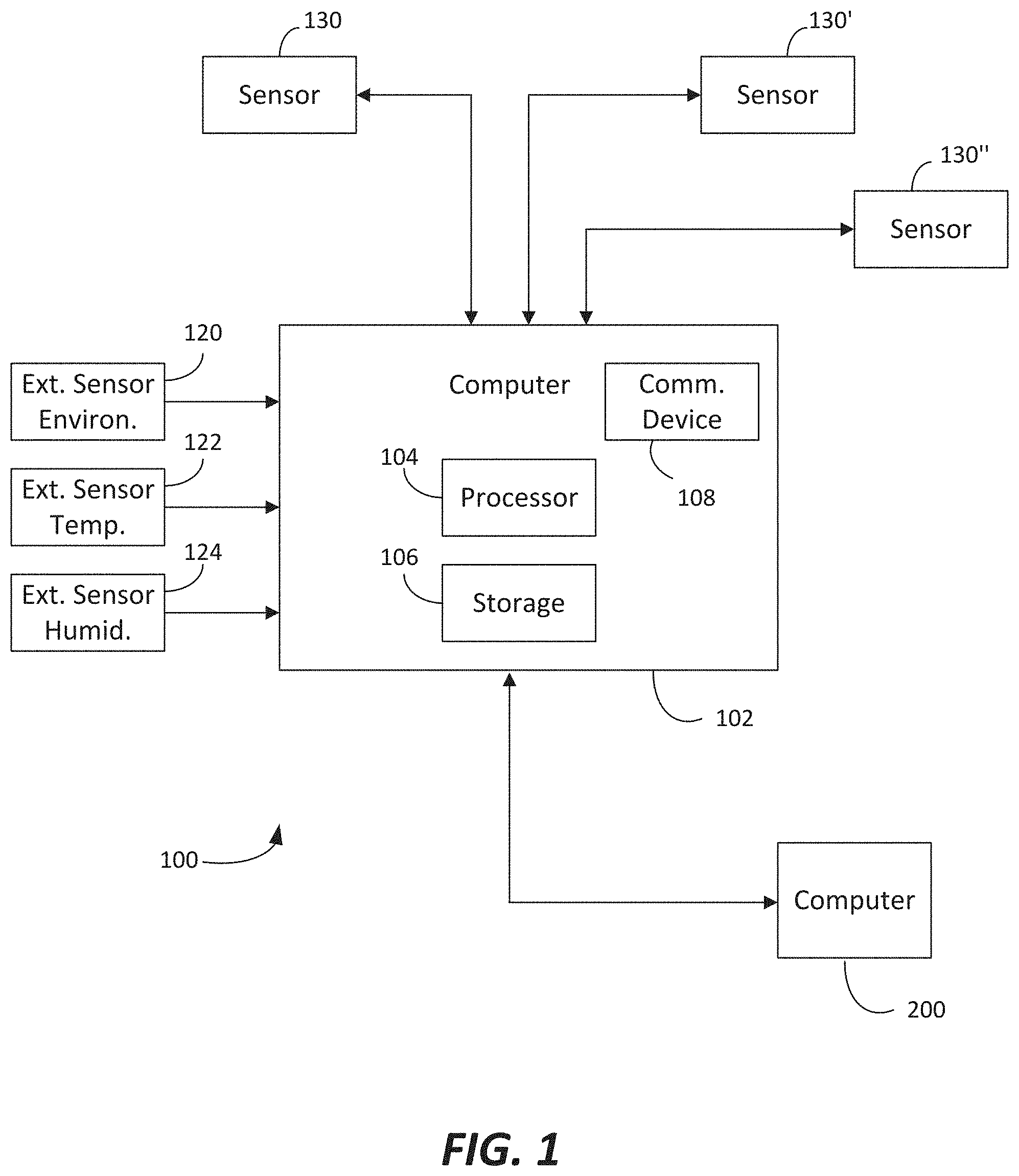
[0034] FIG. 1 is a block diagram illustrating the system for determining energy transfer rates.
[0035] FIG. 2. is a block diagram illustrating the individual sensor in greater detail according to the system of FIG. 1.
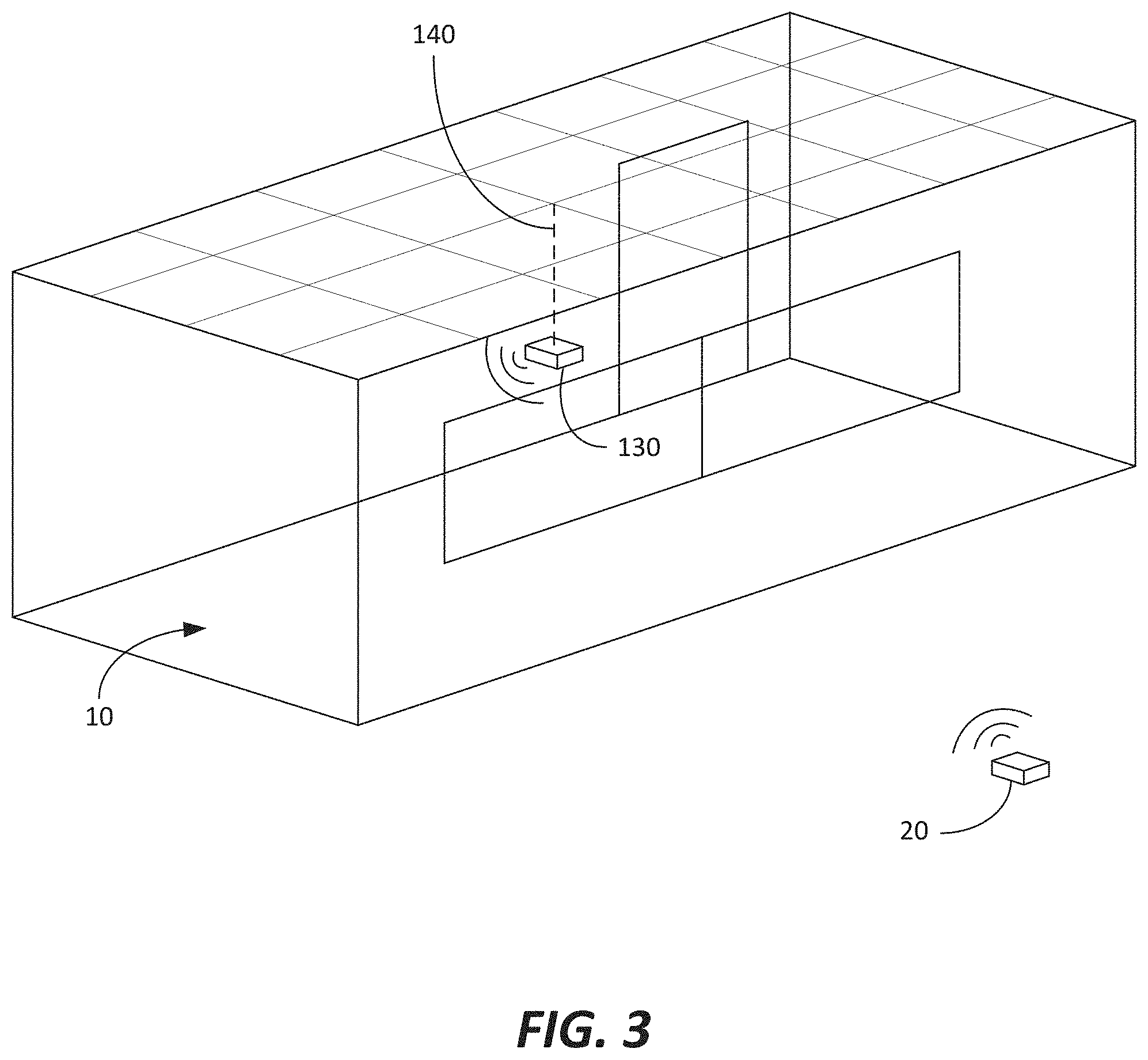
[0036] FIG. 3 an illustration of an installation of the system and the sensing device for measuring energy transfer in a room according to FIG. 1.
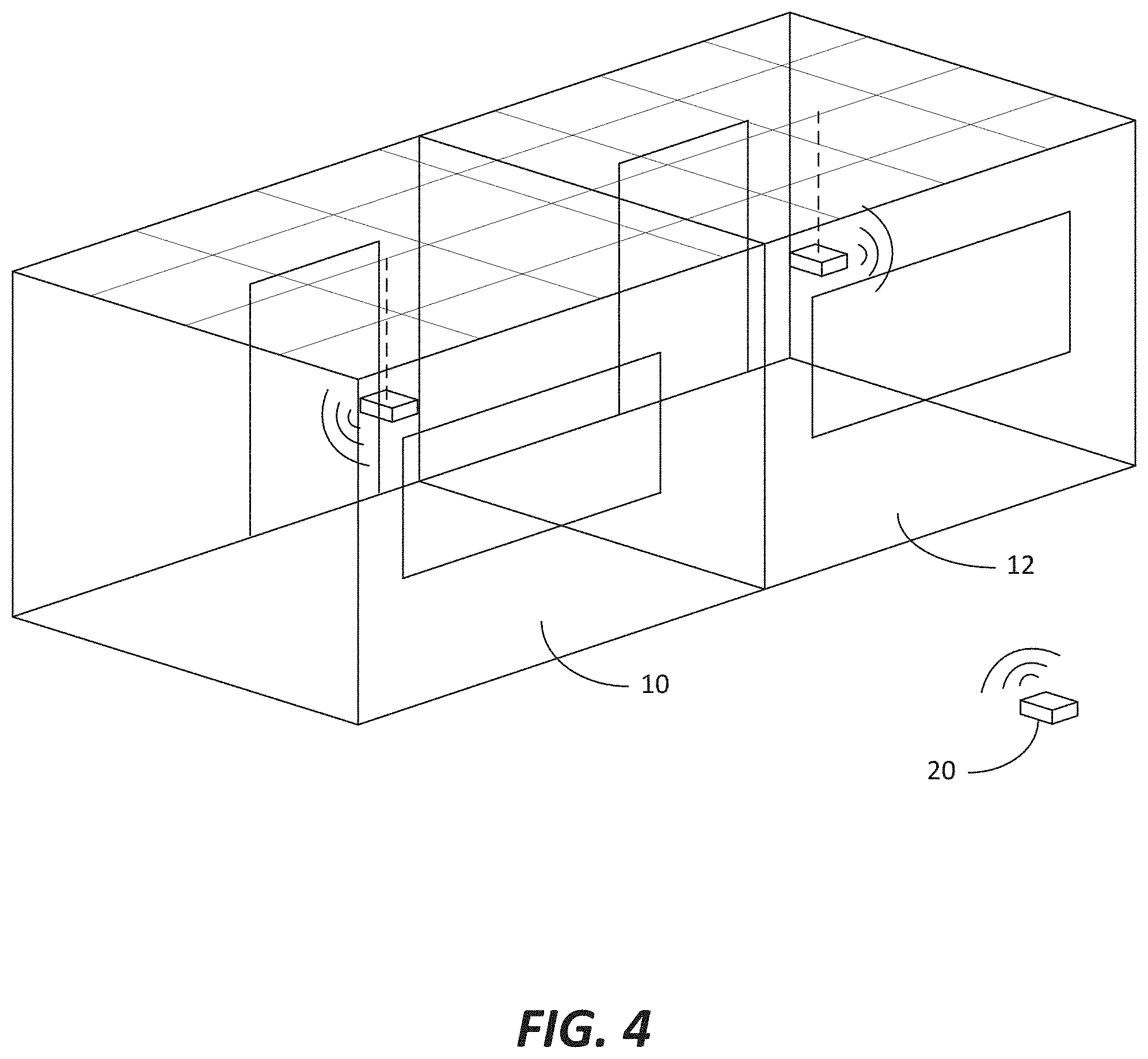
[0037] FIG. 4 is an illustration of an installation of the system and the sensing device for measuring energy transfer in multiple rooms according to FIG. 1.
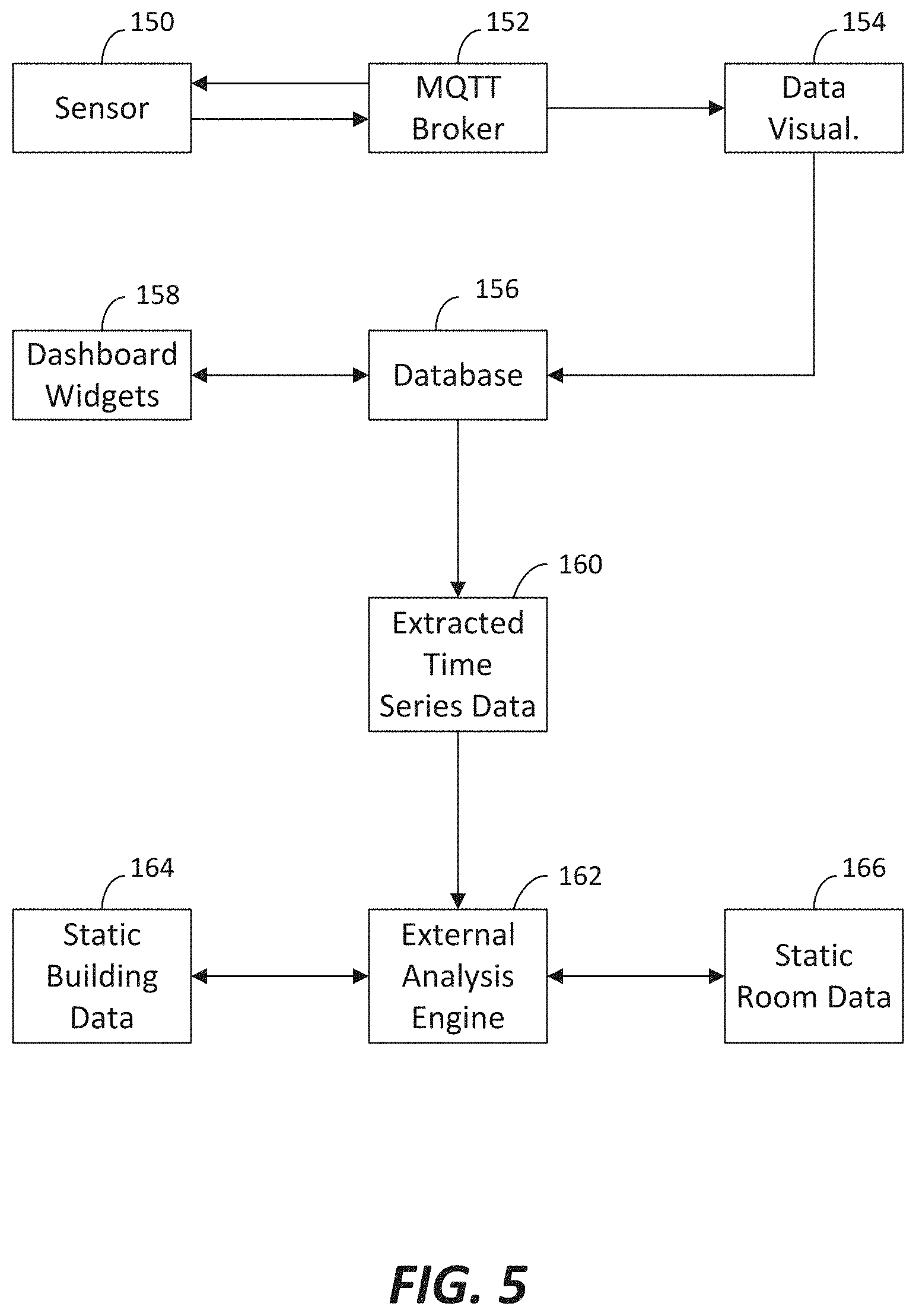
[0038] FIG. 5 is a flow diagram of the processing logic in capturing and monitoring or displaying a sensors data during a test according to the system of FIG. 1.
[0039] FIG. 6 illustrates a sample plot with key areas identified in a cooling cycle to be to be measured by the system of FIG. 1.
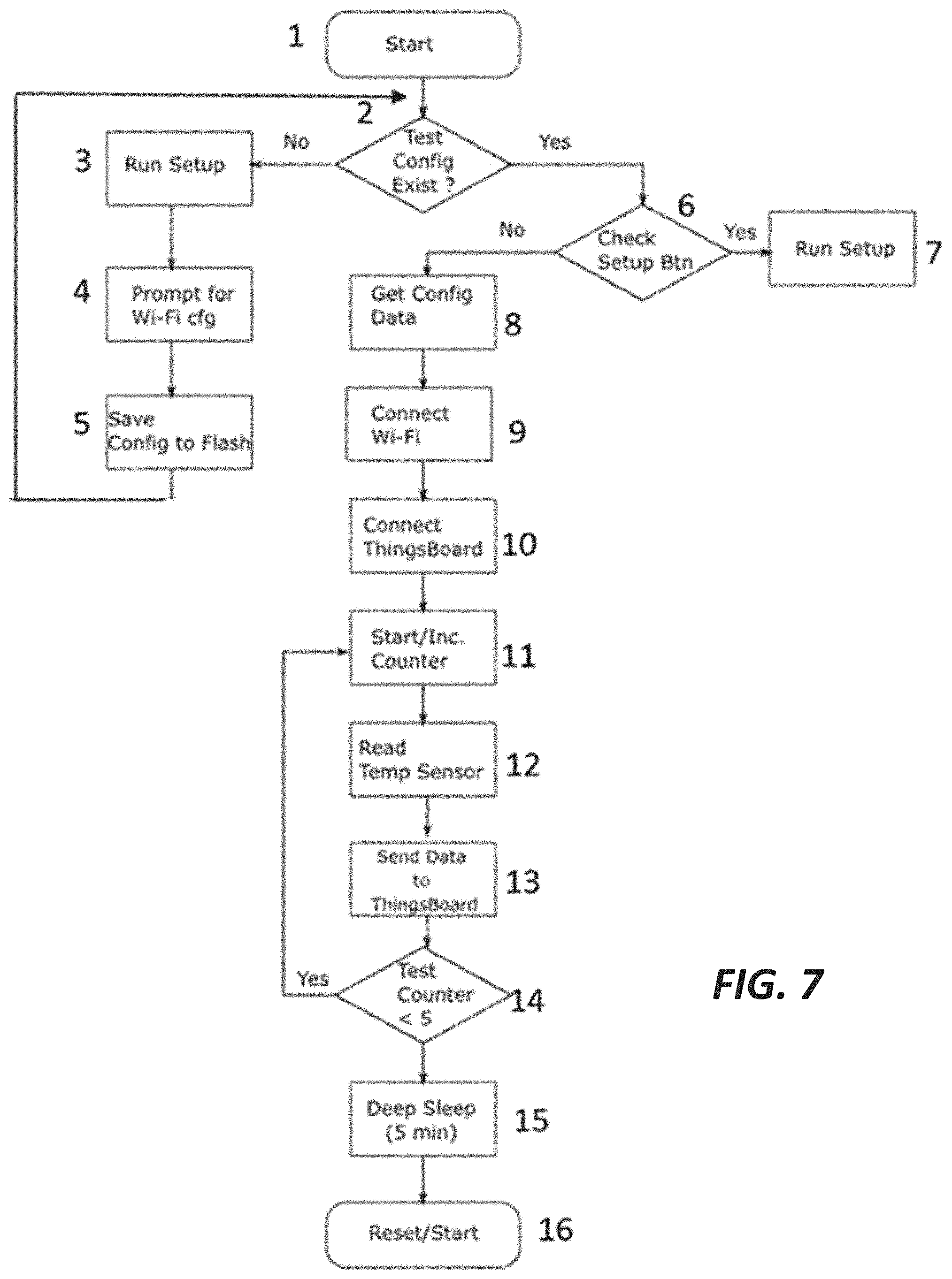
[0040] FIG. 7 is flow diagram for a room sensor according to the system of FIG. 1.
[0041] FIG. 8 is a schematic diagram of a one configuration for the sensor device according to the system of FIG. 1.
DETAILED DESCRIPTION OF THE INVENTION
[0042] Referring now to the drawings, wherein like reference numerals designate corresponding structure throughout the views.
[0043] Turning to the drawings and specifically to FIGS. 1 and 2, FIG. 1 illustrates one configuration for the system 100 for determining an energy transfer rate of a room. The system includes a computer 102 that is coupled to a sensor 130. It is contemplated that multiple sensors 130, 130', 130'' may be coupled to the computer 102. Also shown in FIG. 1, are external sensors including an environmental sensor 120, a temperature sensor 122 and a humidity sensor 124. It will be understood that these external sensors may be locally mounted sensors external to a facility containing the rooms to be measured, or these may be data feeds from a network connection from a local weather measurement station or the like. Additionally, the environmental sensor 120 may comprise a number of different sensors or data feeds providing information for wind speed and direction, solar intensity and so forth. All of this type of environmental data could be factored in and used to calculate the energy transfer rate of a room. While the external sensors 120,122,124 are illustrated as being initially connected to the computer 102, it should be noted that sensors 120,122,124 may be stand-alone systems capable of transmitting their data directly to a central system (not shown) where a remote computer 200 can correlate this data with the sensor(s) 130, 130', 130'' data. The intent of depicting sensors 120,122,124 is to illustrate that the data such sensors can generate can be used by the system to determine an energy transfer rate of the room regardless of how that external sensor data is obtained or routed etc.
[0044] The computer receives the sensor 130 data, which comprises discrete measurements at various time intervals. FIG. 1 is diagrammatic in that the sensors and the various data feeds to computer 102 are illustrated with lines and arrows showing the data connections between the various equipment. However, it will be understood by those of skill in the art that the sensors 130, 130', 130'' may be coupled to computer 102 via a wireless low-power connection (e.g., WiFi, Bluetooth, etc.).
[0045] The computer is illustrated having a processor 104, a storage 106 and a communications interface 108 that is provided to receive and transmit data to and between the sensors 130, 130', 130''. As stated above, the communications interface 108 may be adapted to communicate via a wireless low-power connection (e.g., WiFi, Bluetooth and the like). Storage 106 may include data saved thereon that is used by the processor 104 to process the data generated from environmental measuring device/sensors 132, 132', 132'' and transmitted to computer 102.
[0046] Also illustrated in FIG. 1 is remote computer 200, which could be a computer that is located remotely from the facility or location where the room is being measured/analyzed. Computer 102 may be connected to remote computer 200 via a network connection where remote computer 200 is part of central network that gathers all the data to be used for historical purposes and to generate core expected values for energy transfer rates of a room. In other cases, instead of including remote computer 200, computer 102 may be located remotely from the facility or location and the measurement data may be transmitted directly.
[0047] In particular, the data that would be associated with the energy transfer rate data would include information such as, the construction materials used in the room including for example, the types of wall board and insulation and finish materials, the configuration and types of windows in the room, the flooring materials, the ceiling construction, the location of the room within the larger facility, the geographic facing of the room, the condition of the seals around the windows, the proximity of heat-generating equipment relative to the room, then number impact of heat-generating equipment in the room, etc. All this information can potentially be used to determine an expected energy transfer rate of the room and can be used to generate and/or modify base threshold expected energy transfer rates for the room.
[0048] Additionally, while certain functions such as the scheduling of when measurements are taken by the sensors 130, 130', 130'' may in one configuration be initiated by computer 102, one of skill in the art will understand that software executing on remote computer 200 may send a command to computer 102 to initiate room testing. The software executing on computer 102 may receive the initiate testing command and will then process this data, which in one configuration may include simply passing this command through to the processor 134 or it may be that computer 102 generates a separate or even a supplemental command.
[0049] FIG. 2 shows the sensor 130 of FIG. 1 in greater detail. Sensor 130 includes an environmental measuring device/sensor 132 that may be adapted to measure the temperature of the room in which the sensor 130 is placed. Also shown in FIG. 2 is environmental measuring device/sensor 132' that may be adapted to measure the humidity and environmental measuring device/sensor 132'' that may be adapted to perform other environmental measurements as desired. The various environmental measuring device/sensors 132, 132', 132'' generate data and are coupled to processor 134.
[0050] Also shown in FIG. 2 is a storage 136 that is accessible to processor 134. Storage 136 provides the sensor a storage location for the data received from the various environmental measuring device/sensors 132, 132', 132'', which can be stored until transmitted to computer 102. It is contemplated that the data can be automatically transferred as it is received, however, storage 136 provides for saving of the data in the event a wireless connection cannot be achieved. Alternatively, the processor 134 may automatically transmit the data saved on storage 136 as regular scheduled intervals. In addition to the data received by the various environmental measuring device/sensors 132, 132', 132'', the testing status of the sensor can be saved and transmitted to computer 102.
[0051] A communications interface 138 (hardware) is coupled to processor 134 and is adapted to transmit data to and between computer 102. As stated in connection with FIG. 1, the connection may comprise a wireless low-power connection. A power source 131 is provided that provides power to the environmental measuring device/sensors 132, 132', 132'', the processor 134 and the communications interface 138. The power source 131 may comprise any type of electrical power source such as, for example, a rechargeable battery or the like.
[0052] The sensor 130 also comprises a housing 139 within which the various electronic devices are positioned. The housing is provided with means to connect the sensor to a mounting element 140 such that said sensor 130 is freely positionable within the room or space. This allows for the sensor to be positioned at virtually any location in the space including at various elevations and at various lateral locations. This can be highly desireable to move the sensor 130 about the room so that measurements can be taken at various locations and at various heights as needed. Likewise, if the space is regularly in use, the sensor 130 can be placed in manner that reduces an impact to the use of the space. The mounting element 140 is only diagrammatically illustrated in FIG. 2, but could comprise a device that would allow the sensor 130 to be hung from the ceiling (including for example, a drop ceiling). In one configuration the sensor 130 is approximately centered with respect to the ceiling and floor of the room and measures environmental data at approximately five feet off the ground. Alternatively, the mounting element 140 could free stand on the floor and be movable about the room allowing for the sensor to be suspended at various heights. Still further, the mounting element 140 could comprise a wall-mountable element that allows the sensor 130 to be hung from the wall at various heights and/or be positioned about the room at various location and in the proximity of windows or the like.
[0053] The data transmitted from sensor 130 to computer 102 may further include a code that corresponds to the room in which the sensor 130 is located. This would enable unique identification of each sensor data such that the codes can be matched to the room in which the sensor 130 is mounted and is represented by location 141 input to processor 134.
[0054] Alternatively, location detection can also be built into the sensor as one of the environmental sensors in the form of GPS or other triangulation or location technology which is adaptable and accurate for indoors environments. When placing sensors in an enterprise location, the sensors also incorporate location services which can accurately specify the location of the sensor in a given environment. Technology has evolved to where location services for asset tracking are much more accurate than previous GPS that required satellite communication and was not accurate enough for indoor applications. Triangulation technology and other means can accurately locate latitude, longitude and height making it possible to accurately within a meter to locate a sensing device in an office building.
[0055] Since the sensors may be moved into and out of office locations and used for tests of a transient nature, this localization of the sensor is very important to correlate the results with a given location or customer. When customers and prospects are added, a location is mapped to the software detailing the customer site and where it is located allowing one to identify that a test is being done in a particular customer site. Further, as the sensor is moved into a particular location in the office, a location of latitude, longitude and height is also sent and a room or a particular office mapping can be done when the sensor is placed.
[0056] Alternatively if a floor plan or office map is provided and some initial coordinates can be mapped with the sensor, for example the front door and a few additional points, the localization of the sensor within the office environment or building can be mapped to the floor plan based on the reported location.
[0057] Allowing the sensor to accurately determine its own location and to map this to a known office location based on a floor plan or a relative position within the office is helpful to map the test results to a particular room on the premises where the tests are being conducted.
[0058] It is further contemplated that the sensor 130 may also be equipped with one or more local indicators or displays such as LEDs or a display panel that indicates the status of the test and can enable access to the test results.
[0059] After receiving the measurement data from sensor(s) 130, 130', 130'', computer 102 stores the results in storage 106. This data can be combined and analyzed by the processor 104 and reports or alerts may be generated to indicate test results or status.
[0060] As described above, computer 102 may also receive supplementary data from external feeds, which may be external computers, databases, or news feeds. These feeds could include, external environmental data such as temperature (outside), humidity, wind and other environmental data are received over the wireless interface and stored and combined in local storage 106.
[0061] Turning now to FIG. 3, rendering of an installation of the sensor 130 in a room in a facility is illustrated. The sensor 130 is placed in the room 10 and uses a wireless interface to communicate the results of the measurements. In this configuration, for example, the sensor 130 could be measuring the temperature of room 10. Additionally, the outside temperature could also be measured by means of an outside air temperature measurement device 20. Alternatively, the outside air temperature could comprise a data feed via the network connection. While mounting element 140 is depicted in this configuration as an element allowing sensor 130 to hang down from the ceiling, the mounting element 140 could comprise a floor-mounted element or a wall-mounted element as desired.
[0062] FIG. 4 is a rendering of an installation of multiple sensors 130, 130' located in multiple different rooms 10, 12 in a facility. The sensors 130, 130' could be networked together enabling them to measure multiple spaces. In this instance, they are positioned in different room and connected to a common wireless network to computer 102. Computer 102 collects the temperature and environmental data from sensors 130, 130'. In this configuration, outside air temperature is also monitored and stored to enable a comparison between the outside temperature and the inside temperature to determine the differential. The computer 102 can then communicate the individual or the combined results to computer 200 via an external network. It is also understood that depending on room size, it may be desired to provide multiple sensing devices within the same space/room. In this manner, the rate of change of temperature in different portions of the room could indicate where within the room thermal efficiency leaks are occurring.
[0063] FIG. 5 depicts a flow diagram of the processing logic in capturing and monitoring or displaying a sensors data during a test and is described in a series of logic steps. The room sensor 150 captures temperature readings in a loop at intervals, typically in the 5 second range. The data is then transmitted from the sensor. Within the MQTT message the data is formatted as a JSON (name value pair) message. An MQTT broker 152 captures the data and then transmits it to a visualization module 154, which stores the data in a database 156. From this data in the database, a set of widgets can be developed and used using a widget dashboard 158. Data can also be extracted, for example, like time series data 160, which can be fed to an external analysis engine 162. The external analysis engine 162 can then build up static data sets for the building 164 or for a particular room 166. This model can be replicated for multiple buildings/facilities and rooms and timestamped data can then be correlated between multiple sources and feeds and compared and analyzed.
[0064] FIG. 6 is an illustration of a sample data plot from a room sensor 130 in a room analysis phase with the HVAC system engaged. As can be seen, a typical test cycle (1) where the temperature along they axis decreases with time gradually as in this case, there is a blending of outside air into the room to cool using energy efficient methods. Later, a precooling cycle (2) is initiated getting the building temperature down before the occupants (who generate heat) arrive and making the building comfortable. Finally, in (3) the normal thermostat driven cycles kick in as temperature rises to approximately 74 degrees followed by a decrease, caused by the HVAC equipment turning on and cooling. As the temperature approaches 70 and 71, it can be seen that the curve reverses and temperatures start to rise again as the HVAC equipment is cycled off. These are the typical cycles driven by an electronic thermostat driven HVAC system.
[0065] Referring now to FIG. 7 a functional flow diagram is provided for software running on a sensor 130. Upon initiating (1) the software will check whether or not a configuration exists (2). If not, the software will run a setup (3) routine, which could include prompting for the input of a Wi-Fi password (4) and then saving this configuration to flash memory (5) allowing for it to be used on the next start. Once saved, the software could go back to the start cycle (1).
[0066] If the configuration was detected in (2) then the software could then look for a hardware setup button being pressed (6) and if so would fall into setup mode (7). The setup button is one that is pushed and held during the reset sequence, often with a pin or a sharp tool to avoid going into setup mode by accident as this would cause the loss of configuration data.
[0067] Assuming that the configuration exists in (2) and the setup button is not depressed in (6), the room sensor software goes into its normal operating state for the intended purpose of monitoring and measuring environmental aspects of the room. The software loads the configuration (8) connects to Wi-Fi (9) and connects to the data collection and analysis software (10) which is depicted as ThingsBoard in this example.
[0068] One connected in (10), the software starts looping with a counter which is set to zero initially and subsequently incremented in (11). On each loop, the software reads the temperature sensor data in (12) and sends this data to the collection and analysis software (13) again depicted as ThingsBoard in this example. In FIG. 7, the counter is then compared to a fixed value (14) which has been set to five in the example flow. If less than, it means we have not taken five readings and we will loop back to (11) until having done so.
[0069] Once five readings have been obtained in (14) the software goes into a deep sleep (15) which is a battery saving function. In the example five minutes is used, however, one of skill in the art will recognize that virtually an interval can be configured and set as appropriate for the test scenario. The circuit comes out of deep sleep after the predetermined interval and goes back to the start (1) of the cycle. Note that the deep sleep will not wipe any of the configuration data, so the rerunning of setup would only be initiated by depressing the setup button on startup or reset.
[0070] FIG. 8 depicts a sample schematic diagram of an exemplary sensor 130. The processor 134 depicted here as an ESP8266-12E manufactured by Ai-Thinker and is wired with power circuit 131 driving the module through a power source of two AA batteries. A sample display 133 is shown to highlight results and complement the LEDs that are showed elsewhere in the schematic. A temperature sensor 132 is connected to the processor 134 and is used to gather the raw temperature data. Finally, a reset circuit 135 is shown which forces the module back into setup mode.
[0071] A discussion will now be presented with respect to the measurement and analysis of a room or space for determining an energy transfer rate of the space. In particular, when considering the thermal efficiency of a particular space or room there are a number of factors that have a direct correlation on the thermal efficiency of the room.
[0072] The room volume is a measure of how much air is in a particular space, and as the temperature varies in that space and the volume of air dissipates heat or gains heat as the case may be. Note that for the purposes of this description, cooling and heating will be discussed in the same manner and consideration will only be made of the temperature variation along with the functioning of the HVAC system to control and change the temperature in the space.
[0073] The surface area of the room, including the walls, floor and ceiling make up the envelope that contains the volume of air in the room. The temperature change is correlated to the amount of heat or air that passes through or is in contact with these surfaces. In such a scenario, two rooms of the same size can be compared with the rate at which they change temperature. The one that is better sealed or has walls made of more efficient materials will dissipate less heat than the other. Examples may include solariums or rooms with large windows which would allow more heat to escape than rooms with thick walls made of stone or brick.
[0074] The outside temperature and in particular the A (delta) between the inside and outside temperatures affects the amount of dissipation of heat in or out of the space that is being measured.
[0075] Additional variables can have an impact on thermal efficiency including sunlight, wind, humidity, and such. While these can be factored in and correlated, for simplification a static constant will be applied to differentiate between various classes of spaces. For example, a stand-alone building with all walls and ceiling exposed to the outside elements would be considered one class, while another space that is part of a larger building (e.g., a multi-story strip mall) may have only two walls exposed to the outside and would form a separate distinct class of building. Other distinct classifications include facilities that are inside shopping centers (e.g., a food court), and spaces with many windows or solarium type and open terraces. While it may be possible to accurately factor in each of these variables and types specifically, in most cases, results will be compared in the same space (before and after some renovation or change), or between two comparable spaces (where the external factors will play a similar role for spaces in the same class).
[0076] While the room size including the volume and surface area are constant and straight forward to measure, the temperature reading is an important variable that requires accurate and consistent measurement using both instrumentation and technique in placing such instrumentation to obtain consistent and unhampered test results for the space(s) in question.
[0077] In order to perform this assessment across an enterprise it would generally be necessary to have a group of connected temperature sensors distributed throughout an enterprise that will report time stamped temperature data to a centralized database. That data can be analyzed and assessed to determine the locations throughout the organization where the room envelope could benefit from additional energy performance improvements. Further, when making any updates that may affect energy performance, such a system can be used to measure and compare results to evaluate the effectiveness of these improvements with before and after values.
[0078] The sensors 130, 130', 130'' that have been previously discussed would need to meet the following requirements: [0079] Wireless operation--the ability to transmit temperature information wirelessly via Wi-Fi network. The sensors should be capable of working with 802.11 b/g/n networks or equivalent. [0080] Real-time temperature updates--The sensor should be capable of publishing temperature updates at intervals of 5 seconds or less. [0081] Battery operation--The sensor should be capable of operating for the length of a multi-day test and would ideally employ rechargeable batteries, or even incorporate solar charging capabilities. In some longer-term measurement applications, the operating time should reach 1 year or more. [0082] Configurable--The sensor should be configurable so that it may allow for different Wi-Fi SSIDs and network passwords as it is used in a variety of locations. The sensor should also accommodate the ability to add physical location details to the device configuration. [0083] Range and Accuracy--The accuracy of the temperature sensor should be accurate to +/-0.5 C from -10 C to 85 C. [0084] Security--the design of the sensor should prevent intrusion into the sensor network and any attempts to navigate through the network to other connected hosts should be prevented. As an option support for the WPA2 Enterprise wireless network security protocol or better should be available. [0085] Standalone operation--the sensor should also be equipped with an optional display that can show results of independent tests in the form of blinking multicolor LEDs to show status such as: test started, in progress, complete, error etc. Values can also be shown on the display. [0086] Capacity--The device must also employ a processor such as an ESP8266-12E system on chip (SoC) or equivalent and also include a temperature sensor capable of delivering real-time temperature readings such as a DS18620 single wire temperature sensor manufactured by Dallas Semiconductor.
[0087] The access point provides the Wi-Fi network connectivity for the sensor network. For this application, either the customer network can be used, or a temporary network can be brought in for the purpose of collecting data during the period of time when the room envelope integrity evaluation is underway.
[0088] A temporary network infrastructure to accommodate the network of IoT devices (room sensors) will simplify the process of deploying the network and gathering fine grained room level temperature data. A standalone cellular based router providing access to the devices and a laptop to gather the data can be used or the equivalent.
[0089] Data from the sensor is read and put into a table for subsequent analysis and display using a database and can be read by visualization software to deliver and display the results in an easy to read and see format. Analytics can be performed on the data using any number of analytics and predictive analytics platforms.
[0090] The following example table defines static data and time series sensor data used in preliminary testing:
TABLE-US-00001 TABLE 1 Static Data Data Element Name Description Remarks Building Address for Building Location Floor Floor of the building Room Location Location of the room Room ID Room identifier Unique identifier associated with a room Room Geo coordinates of the Coordinates room Room Type Type of room e.g., individual office, conference room, corridor, storage room, etc. Room exterior Number of exterior walls walls Room Interior Number of interior walls walls Room wall Description of the wall material material being used Room Ceiling The ceiling height of the Height room Room Ceiling The type of ceiling used Type in the room Room Floor They type of floor of the Type room Room Sq ft The square footage of the room Other Room Description of other room A basic description of the Attributes attributes room attributes, such as glass walls, open concept, etc. Outside Air Temperature of the outside Taken at the time of the Temp air temperature test Adjacent space Temperature in adjacent Taken at the time of the temperature spaces test -this may be an array of multiple temperature readings Ceiling Plenum Temperature in the air Taken at the time of the air temperature space above the ceiling test
[0091] The test process used is such that the sensors are placed in a location within the room that is temperature stable, for example, a location that is out of direct sunlight and away from surfaces that may conduct temperature. The sensor may, for example, be suspended from the ceiling using a small diameter wire so that the sensor remains at a height equidistant from the floor and ceiling in an area in the middle of the room.
[0092] The sensor should be placed in a location providing a reasonable representation of the average temperature of the room. Where possible, this placement must be consistent for multiple rooms when doing comparisons. i.e. distance from floor and ceiling and the distance from openings should be consistent across rooms.
[0093] In one configuration, the system may utilize a two-part testing approach as a means to gather the data necessary to assess the environment under test. Part one is a room envelope test, and this test attempts to eliminate the impact of the HVAC system from the room environment. The second part of the test is a room temperature monitoring test and will monitor the temperature of the room environment for anywhere between two and seven days. The first part of the test assesses the ability of the space to resist temperature change, the second part of the test will provide data to determine how well the HVAC system performs for that particular room location. Although both tests provide valuable data on their own, the combination of these two tests provides valuable insights into the performance of both the building envelope and HVAC system at the room level.
[0094] For the Room Envelope Test, once the sensor has been placed in the room and the temperature in the room has stabilized (this period of time depends on the size of the room, but for a 10.times.10 office, the period of time should be about 15 to 20 minutes) the HVAC system will be disabled. Ideally the return air vent will be blocked, and the temperature sensor will be started. The computer will begin gathering data within 30 seconds and the sensor will be programmed to take a temperature reading every 5 minutes for the next hour.
[0095] In order to be minimally disruptive to the working environment, the duration of the test period for the Room Envelope test may be kept to one hour. It is possible to conduct other longer tests after working hours, but it is found that the test results are consistent between the shorter and longer tests and this is unnecessary in most cases. Cases where smaller variations in highly efficient rooms are to be measured may be an exception. After a field test of the room sensors a determination is made to decide whether a single one-hour test is sufficient for assessing the room envelope.
[0096] The Room Temperature Monitoring test is the second part of the test and is intended to monitor the temperature of the room over several days. Monitoring the temperature of the room 24 hours a day over a multi-day period will provide valuable insights into the ability of the HVAC system to maintain a comfortable room environment during periods of time when the room is occupied as well as identify potential problems related to the HVAC setbacks. Improperly configured setbacks can be a contributing major factor for excess energy consumption.
[0097] The time series data gathered by these tests is the data gathered by the individual temperature sensors. Although the ESP8266-12E/DS18620 temperature sensor used in the prototyping is capable of delivering a temperature reading per second, for the purpose of this analysis that data frequency is not believed to be necessary. In order to maximize battery life in the remote sensor, the temperature sensor is configured to deliver twelve (12) temperature readings per hour or one reading every five (5) minutes. This variation of sensor reading timing is simply an example, and should not be viewed as limiting. Data can be gathered in a variety of timing increments and generally speaking, the more frequently it is measured the more accurate and granular the results will be.
[0098] An example of the data reported at the sensor level is depicted in the following table:
TABLE-US-00002 TABLE 2 Data Element Name Description Sensor ID information Sensor ID to correlate with placement. Timestamp Timestamp for each measure Temp Temperature Humidity Percentage of humidity
[0099] The objective of the data analysis is to identify and isolate areas of the building that do not maintain temperature as well as others. The analysis will allow those poor performing areas to be targeted for building envelope improvements. The following outlines the process and lists the variables to be analyzed.
[0100] As a means for providing a consistent measure for the rate that a room warms or cools, the data gathered in the course of the testing can be used to gather the essential input data to calculate the cooling constant of the room. This cooling constant can be derived from Newtown's law of cooling that states that the rate of change of the temperature of an object is proportional to the difference between its own temperature and the ambient temperature (i.e., the temperature of its surroundings). By understanding the rate of change in each area being evaluated it is possible to produce an objective score that us useful for assessing the envelope properties of a room.
[0101] Simple Temperature over Time. The temperature sensor will gather 12 readings per hour in the default setting of five-minute data gathering windows. This data will be characterized in a table with the parameters listed in the example sensor data over time.
[0102] A thermal efficiency metric is determined using [0103] a. Temperature variation over time [0104] b. External temperature [0105] c. Volume of the room/space [0106] d. Surface area of the room/space
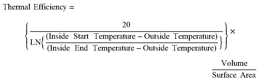
[0107] Mathematically, the Thermal Efficiency is calculated as follows:
Thermal Efficiency = { 20 LN { ( Inside Start Temperature - Outside Temperature ) ( Inside End Temperature - Outside Temperature ) } } .times. Volume Surface Area ##EQU00001##
*Note that a value of 20 is used to smooth out the values, however this is illustrative and depending on the application and target range this constant can be modified or omitted.
[0108] Although the invention has been described with reference to a particular arrangement of parts, features and the like, these are not intended to exhaust all possible arrangements or features, and indeed many other modifications and variations will be ascertainable to those of skill in the art.
* * * * *
References
D00000
D00001
D00002
D00003
D00004
D00005
D00006
D00007
D00008
XML
uspto.report is an independent third-party trademark research tool that is not affiliated, endorsed, or sponsored by the United States Patent and Trademark Office (USPTO) or any other governmental organization. The information provided by uspto.report is based on publicly available data at the time of writing and is intended for informational purposes only.
While we strive to provide accurate and up-to-date information, we do not guarantee the accuracy, completeness, reliability, or suitability of the information displayed on this site. The use of this site is at your own risk. Any reliance you place on such information is therefore strictly at your own risk.
All official trademark data, including owner information, should be verified by visiting the official USPTO website at www.uspto.gov. This site is not intended to replace professional legal advice and should not be used as a substitute for consulting with a legal professional who is knowledgeable about trademark law.