Matrix Type Double Parallel Capillary Tube Shock Absorber With A Variable System Natural Frequency
RONG; Qiang
U.S. patent application number 16/470267 was filed with the patent office on 2020-03-19 for matrix type double parallel capillary tube shock absorber with a variable system natural frequency. This patent application is currently assigned to SOUTH CHINA UNIVERSITY OF TECHNOLOGY. The applicant listed for this patent is SOUTH CHINA UNIVERSITY OF TECHNOLOGY. Invention is credited to Qiang RONG.
| Application Number | 20200088263 16/470267 |
| Document ID | / |
| Family ID | 58926548 |
| Filed Date | 2020-03-19 |


| United States Patent Application | 20200088263 |
| Kind Code | A1 |
| RONG; Qiang | March 19, 2020 |
MATRIX TYPE DOUBLE PARALLEL CAPILLARY TUBE SHOCK ABSORBER WITH A VARIABLE SYSTEM NATURAL FREQUENCY
Abstract
Provided is a matrix type double parallel capillary tube shock absorber with a variable system natural frequency, wherein on a pipeline between oil supply ports of an upper oil compartment (14) and a lower oil compartment (16), a capillary tube parallel type damping associated section and a capillary tube parallel type system natural frequency associated section are successively connected from top to bottom; the capillary tube parallel type damping associated section comprises four capillary tubes connected in parallel, with each capillary tube being connected in series with a solenoid valve so as to control the operation of the capillary tube; the capillary tube parallel type system natural frequency associated section comprises four capillary tubes connected in parallel, and each of the four capillary tubes is connected in series with a solenoid valve so as to control the operation of the capillary tube; the diameter of the smallest capillary tube of the frequency adjustment section is much larger than the diameter of the capillary tube of the resistance adjustment section; and in a matrix type operation state table, the configuration value S.sub.mn of the solenoid valves of the frequency adjustment section is selected according to situations, and by way of changing the mass, the problem of the system natural frequency of a hydraulic shock absorber for a vehicle being not adjustable or having a small adjustable range can be solved. Further provided is a method for operating a matrix type double parallel capillary tube shock absorber with a variable system natural frequency.
| Inventors: | RONG; Qiang; (Guangzhou City, CN) | ||||||||||
| Applicant: |
|
||||||||||
|---|---|---|---|---|---|---|---|---|---|---|---|
| Assignee: | SOUTH CHINA UNIVERSITY OF
TECHNOLOGY Guangzhou City CN |
||||||||||
| Family ID: | 58926548 | ||||||||||
| Appl. No.: | 16/470267 | ||||||||||
| Filed: | November 28, 2017 | ||||||||||
| PCT Filed: | November 28, 2017 | ||||||||||
| PCT NO: | PCT/CN2017/113373 | ||||||||||
| 371 Date: | June 17, 2019 |
| Current U.S. Class: | 1/1 |
| Current CPC Class: | F16F 13/007 20130101; F16F 9/34 20130101; F16F 2230/18 20130101; F16F 2228/04 20130101 |
| International Class: | F16F 13/00 20060101 F16F013/00; F16F 9/34 20060101 F16F009/34 |
Foreign Application Data
| Date | Code | Application Number |
|---|---|---|
| Dec 27, 2016 | CN | 201611223458.9 |
Claims
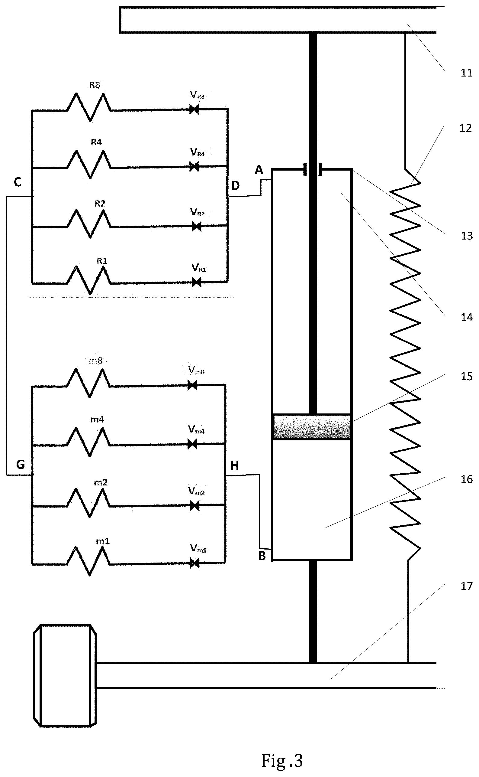
1. A matrix type double parallel capillary tube shock absorber with a variable system natural frequency, which comprises a vehicle frame (11), an axle (17) and a hydraulic cylinder (13), an upper end of the hydraulic cylinder (13) being connected to the vehicle frame (11) via a piston rod of the hydraulic cylinder, and a lower end of a cylinder body of the hydraulic cylinder (13) being connected to the axle (17); and a piston (15) inside the hydraulic cylinder (13) dividing the hydraulic cylinder (13) into an upper oil compartment (14) and a lower oil compartment (16); wherein on a pipeline between oil supply ports of the upper oil compartment (14) and the lower oil compartment (16), a capillary tube parallel type damping associated section and a capillary tube parallel type system natural frequency associated section are successively connected from top to bottom, that is, a D oil port of the capillary tube parallel type damping associated section is connected to an A oil port of the upper oil compartment (14), a C oil port of the capillary tube parallel type damping associated section is connected to a G oil port of the capillary tube parallel type system natural frequency associated section, and an H oil port of the capillary tube parallel type system natural frequency associated section is connected to a B oil port of the lower oil compartment (16).
2. The matrix type double parallel capillary tube shock absorber with a variable system natural frequency of claim 1, wherein the capillary tube parallel type damping associated section comprises four capillary tubes successively connected in parallel, with each capillary tube being connected in series with a solenoid valve; and the capillary tube parallel type system natural frequency associated section comprises four capillary tubes connected in parallel, and the four capillary tubes are each connected in series with a solenoid valve.
3. The matrix type double parallel capillary tube shock absorber with a variable system natural frequency of claim 2, wherein a capillary tube parallel-connection end of the capillary tube parallel type system natural frequency associated section is the G oil port, and a solenoid valve parallel-connection end is the H oil port.
4. The matrix type double parallel capillary tube shock absorber with a variable system natural frequency of claim 2, wherein the lengths of the four capillary tubes of the capillary tube parallel type system natural frequency associated section are equal.
5. The matrix type double parallel capillary tube shock absorber with a variable system natural frequency of claim 2, wherein the ratio of the cross-sectional areas of the four capillary tubes of the capillary tube parallel type system natural frequency associated section is 8:4:2:1, that is, their cross-sectional areas are arranged according to a binary coding rule of 8421.
6. The matrix type double parallel capillary tube shock absorber with a variable system natural frequency of claim 5, wherein among the four capillary tubes of the capillary tube parallel type system natural frequency associated section, the diameter d.sub.m1 of the smallest capillary m1 is not less than twice the diameter d.sub.R8 of the largest capillary tube R8 of the capillary tube parallel type damping associated section.
7. The matrix type double parallel capillary tube shock absorber with a variable system natural frequency of claim 1, wherein the capillary tubes in the capillary tube parallel type damping associated section and the capillary tube parallel type system natural frequency associated section are all formed into an "M" shape, an "S" shape or a spiral shape.
8. The matrix type double parallel capillary tube shock absorber with a variable system natural frequency of claim 7, wherein the solenoid valves in the capillary tube parallel type damping associated section and the capillary tube parallel type system natural frequency associated section are further connected to a capillary tube control system; and the capillary tube control system is configured to control the turning on and the turning off of each solenoid valve.
9. The matrix type double parallel capillary tube shock absorber with a variable system natural frequency of claim 7, a spring (12) is provided between the vehicle frame (11) and the axle (17).
10. A method for operating the matrix type double parallel capillary tube shock absorber with a variable system natural frequency of claim 1, comprising the following steps: when a relative movement between the vehicle frame and the axle occurs, the piston correspondingly moves up or down, and at this time, an oily liquid in the hydraulic cylinder (13) passes through the capillary tube parallel type damping associated section and the capillary tube parallel type system natural frequency associated section between the A oil port and the B oil port, and then flows from the upper oil compartment (14) to the lower oil compartment (16), or from the lower oil compartment (16) to the upper oil compartment (14); due to the viscous effect of the oily liquid in the cylinder body, when the oily liquid flows through the capillary tube parallel type damping associated section, the capillary tubes operating in the capillary tube parallel type damping associated section dampen the flow of the oily liquid, thereby forming a resistance against the movement of the piston, wherein the magnitude of the resistance is controlled by the capillary tube control system based on the configuration S.sub.Rn of the solenoid valves, thereby realizing the resistance adjustment for the capillary tube parallel type damping associated section; and when the oily liquid flows through the capillary tube parallel type system natural frequency associated section, with the capillary tube control system changing the configuration S.sub.mn of the solenoid valves, the system natural frequency of the shock absorber can be adjusted, thereby realizing the frequency adjustment for the capillary tube parallel type system natural frequency associated section.
Description
TECHNICAL FIELD
[0001] The present invention relates to the field of hydraulic shock absorbers for vehicles, and in particularly to a matrix type double parallel capillary tube shock absorber with a variable system natural frequency.
BACKGROUND ART
[0002] There are mainly hydraulic, pneumatic and electromagnetic shock absorbing methods for vehicles. At present, the hydraulic shock absorbing method is the most widely used in vehicles. The system natural frequency of the hydraulic shock absorber is an important performance indicator of the shock absorber for the vehicle. At present, one of the disadvantages of the performance of the hydraulic shock absorber is that the system natural frequency of the shock absorber is not adjustable or has a small adjustable range.
[0003] The quality of the system natural frequency of the hydraulic shock absorber for the vehicle will directly affect the vibration amplitude, comfort and smoothness of the vehicle during traveling.
[0004] It is well known that for an ideal spring oscillator, as shown in FIG. 1, the system natural frequency of the spring oscillator is inversely proportional to the square root of the mass of a ball of the spring oscillator. That is to say, when the mass of the ball is changed, the system natural frequency will change. The smaller the mass of the ball, the higher the system natural frequency. The higher the mass of the ball, the lower the system natural frequency.
[0005] As shown in FIG. 2, four capillary tubes are capillary tubes R8, R4, R2 and R1, respectively; and they are of equal length and are respectively connected to solenoid valves V.sub.R8, V.sub.R4, V.sub.R2 and V.sub.R1 in series so as to control their operation. The ratio of the cross-sectional areas of the four capillary tubes is 8:4:2:1; that is, their cross-sectional areas are arranged according to a binary coding rule of 8421.
[0006] As shown in FIG. 2, the configuration S.sub.Rn of the solenoid valves V.sub.R8, V.sub.R4, V.sub.R2, and V.sub.R1 of the shock absorber will be determined according to the damping requirements (the range of values of n is 0, 1, 2, . . . , 15, where S.sub.R0 indicates that the solenoid valves V.sub.R8, V.sub.R4, V.sub.R2, and V.sub.R1 are all turned off; S.sub.R1 indicates that only V.sub.R1 among V.sub.R8, V.sub.R4, V.sub.R2, and V.sub.R1 is turned on, and the rest are turned off; S.sub.R2 indicates that only V.sub.R2 is turned on, and the rest is turned off; S.sub.R3 indicates that only V.sub.R2 and V.sub.R1 are turned on, and the rest are turned off; and so on for S.sub.R4 to S.sub.R15). When the configuration S.sub.Rn is determined, the mass M.sub.Rn of a fluid in the shock absorber that participates in the oscillation for shock absorption is also determined. Compared with the spring oscillator, the mass M.sub.Rn is similar to the mass of the ball of the spring oscillator. Therefore, at this time, the system natural frequency of the shock absorber is then determined, so the natural frequency is not adjustable in the determined configuration S.sub.Rn.
SUMMARY OF THE INVENTION
[0007] An object of the present invention is, in order to overcome the above-mentioned shortcomings and drawbacks of the prior art, to provide a matrix type double parallel capillary tube shock absorber with a variable system natural frequency, which aims to improve the system natural frequency characteristics of a hydraulic shock absorber for a vehicle.
[0008] The present invention is achieved by the following technical solutions:
[0009] a matrix type double parallel capillary tube shock absorber with a variable system natural frequency, which comprises a vehicle frame 11, an axle 17 and a hydraulic cylinder 13, an upper end of the hydraulic cylinder 13 being connected to the vehicle frame 11 via a piston rod of the hydraulic cylinder, and a lower end of a cylinder body of the hydraulic cylinder 13 being connected to the axle 17; and a piston 15 inside the hydraulic cylinder 13 dividing the hydraulic cylinder 13 into an upper oil compartment 14 and a lower oil compartment 16;
[0010] wherein on a pipeline between oil supply ports of the upper oil compartment 14 and the lower oil compartment 16, a capillary tube parallel type damping associated section and a capillary tube parallel type system natural frequency associated section are successively connected from top to bottom, that is, a D oil port of the capillary tube parallel type damping associated section is connected to an A oil port of the upper oil compartment 14, a C oil port of the capillary tube parallel type damping associated section is connected to a G oil port of the capillary tube parallel type system natural frequency associated section, and an H oil port of the capillary tube parallel type system natural frequency associated section is connected to a B oil port of the lower oil compartment 16.
[0011] The capillary tube parallel type damping associated section comprises four capillary tubes successively connected in parallel, with each capillary tube being connected in series with a solenoid valve; and the function of the solenoid valve is to control the turning on and the turning off of the capillary tube.
[0012] The capillary tube parallel type system natural frequency associated section comprises four capillary tubes connected in parallel, and the four capillary tubes are each connected in series with a solenoid valve; and the function of the solenoid valve is to control the turning on and the turning off of the capillary tube.
[0013] A capillary tube parallel-connection end of the capillary tube parallel type system natural frequency associated section is the G oil port, and a solenoid valve parallel-connection end is the H oil port.
[0014] The lengths of the four capillary tubes of the capillary tube parallel type system natural frequency associated section are equal.
[0015] The ratio of the cross-sectional areas of the four capillary tubes of the capillary tube parallel type system natural frequency associated section is 8:4:2:1, that is, their cross-sectional areas are arranged according to a binary coding rule of 8421.
[0016] Among the four capillary tubes of the capillary tube parallel type system natural frequency associated section, the diameter d.sub.ml of the smallest capillary ml is not less than twice the diameter d.sub.R8 of the largest capillary tube R8 of the capillary tube parallel type damping associated section.
[0017] The capillary tubes in the capillary tube parallel type damping associated section and the capillary tube parallel type system natural frequency associated section are all formed into an "M" shape, an "S" shape or a spiral shape.
[0018] The solenoid valves in the capillary tube parallel type damping associated section and the capillary tube parallel type system natural frequency associated section are further connected to a capillary tube control system; and the capillary tube control system is configured to control the turning on and the turning off of each solenoid valve.
[0019] A spring 12 is provided between the vehicle frame 11 and the axle 17.
[0020] A method for operating the matrix type double parallel capillary tube shock absorber with a variable system natural frequency of the present invention comprises the following steps:
[0021] when a relative movement between the vehicle frame and the axle occurs, the piston correspondingly moves up or down, and at this time, an oily liquid in the hydraulic cylinder 13 passes through the capillary tube parallel type damping associated section and the capillary tube parallel type system natural frequency associated section between the A oil port and the B oil port, and then flows from the upper oil compartment 14 to the lower oil compartment 16, or from the lower oil compartment 16 to the upper oil compartment 14;
[0022] due to the viscous effect of the oily liquid in the cylinder body, when the oily liquid flows through the capillary tube parallel type damping associated section, the capillary tubes operating in the capillary tube parallel type damping associated section dampen the flow of the oily liquid, thereby forming a resistance against the movement of the piston, wherein the magnitude of the resistance is controlled by the capillary tube control system based on the configuration S.sub.Rn of the solenoid valves, thereby realizing the resistance adjustment for the capillary tube parallel type damping associated section; and
[0023] when the oily liquid flows through the capillary tube parallel type system natural frequency associated section, with the capillary tube control system changing the configuration S.sub.mn of the solenoid valves, the system natural frequency of the shock absorber can be adjusted, thereby realizing the frequency adjustment for the capillary tube parallel type system natural frequency associated section.
[0024] The method for operating the shock absorber of the present invention is further illustrated below:
[0025] when a relative movement between the vehicle frame and the axle occurs, the piston correspondingly moves up or down, and at this time, an oily liquid in the hydraulic cylinder 13 passes through the capillary tube parallel type damping associated section (hereinafter referred to as resistance adjustment section) and the capillary tube parallel type system natural frequency associated section (hereinafter referred to as frequency adjustment section) between the A oil port and the B oil port, and then flows from the upper oil compartment 14 to the lower oil compartment 16, or from the lower oil compartment 16 to the upper oil compartment 14.
[0026] Due to the viscous effect of the oily liquid in the cylinder body, when the oily liquid flows through the resistance adjustment section, the capillary tubes of the resistance adjustment section will dampen the flow of the oily liquid, thereby forming a resistance against the movement of the piston, wherein the magnitude of the resistance is controlled by the capillary tube control system based on the configuration S.sub.Rn of the solenoid valves, thereby realizing the resistance adjustment for the resistance adjustment section.
[0027] After the configuration S.sub.Rn of the resistance adjustment section of the shock absorber is determined according to the damping requirements, the configuration S.sub.mn of the solenoid valves V.sub.m8, V.sub.m4, V.sub.m2 and V.sub.m1 of the frequency adjustment section of the shock absorber will be determined according to the requirements for the natural frequency. For S.sub.mn, the range of values of n is 0, 1, 2, . . . , 15, where S.sub.m0 indicates that the solenoid valves V.sub.m8, V.sub.m4, V.sub.m2 and V.sub.m1 are all turned off; S.sub.m1 indicates that only V.sub.m1 among V.sub.m8, V.sub.m4, V.sub.m2 and V.sub.m1 is turned on, and the rest is turned off; S.sub.m2 indicates that only V.sub.m2 is turned on, and the rest is turned off; S.sub.m3 indicates that only V.sub.m2 and V.sub.m1 are turned on, and the rest are turned off; and so on for S.sub.m4 to S.sub.m15.
[0028] When the configuration S.sub.mn of the frequency adjustment section is determined, the mass M.sub.mn of a fluid participating in the oscillation in the frequency adjustment section is also determined. Accordingly, the mass of the fluid in the shock absorber that participates in the oscillation for shock absorption is M.sub.Rn+M.sub.mn (where M.sub.Rn is the mass of the fluid participating in the oscillation in the resistance adjustment section). Compared with a spring oscillator, the combined mass of the masses M.sub.Rn and M.sub.mn is similar to the mass of the ball of the spring oscillator. We change the combined mass of M.sub.Rn and M.sub.mn by changing M.sub.mn so as to change the system natural frequency of the shock absorber.
[0029] Since the diameters of the capillary tubes of the frequency adjustment section are all much larger than the diameters of the capillary tubes of the resistance adjustment section, the loss of pressure head of the frequency adjustment section is much smaller than that of the resistance adjustment section. In this way, the damping of the shock absorber mainly is the damping of the resistance adjustment section, so that the capillary tube parallel type damping associated section is also referred to as the resistance adjustment section. Further, since the frequency adjustment section has little effect on the damping, but it can change the system natural frequency of the shock absorber, the capillary tube parallel type system natural frequency associated section is referred to as the frequency adjustment section. Further, since the resistance adjustment section is adjusted by parallel capillary tubes, and the frequency adjustment section is also adjusted by parallel capillary tubes, the system is a double parallel capillary tube shock absorber (the first "parallel" indicates that the operation mode of the resistance adjustment section is a parallel mode, and the second "parallel" indicates that the operation mode of the frequency adjustment section is also a parallel mode).
[0030] Since the damping of the frequency adjustment section is small and the diameter of the capillary tube of the frequency adjustment section is relatively large, we can easily make M.sub.mn much larger than M.sub.Rn by increasing the length of the capillary tube of the frequency adjustment section, so that the adjustment range of the system natural frequency of the shock absorber can be made very large.
[0031] The resistance adjustment section and the frequency adjustment section of the shock absorber operate in series, and the state of the resistance adjustment section is determined based on the configuration S.sub.Rn, and the state of the frequency adjustment section is determined based on the configuration S.sub.mn. Therefore, the operation state of the shock absorber can be expressed by the following table.
[0032] Theoretical operation state table of the shock absorber:
TABLE-US-00001 S.sub.mn S.sub.Rn S.sub.m0 S.sub.m1 S.sub.m2 . . . S.sub.m13 S.sub.m14 S.sub.m15 S.sub.R0 (S.sub.R0 S.sub.m0) (S.sub.R0 S.sub.m1) (S.sub.R0 S.sub.m2) . . . (S.sub.R0 S.sub.m13) (S.sub.R0 S.sub.m14) (S.sub.R0 S.sub.m15) S.sub.R1 (S.sub.R1 S.sub.m0) (S.sub.R1 S.sub.m1) (S.sub.R1 S.sub.m2) . . . (S.sub.R1 S.sub.m13) (S.sub.R1 S.sub.m14) (S.sub.R1 S.sub.m15) S.sub.R2 (S.sub.R2 S.sub.m0) (S.sub.R2 S.sub.m1) (S.sub.R2 S.sub.m2) . . . (S.sub.R2 S.sub.m13) (S.sub.R2 S.sub.m14) (S.sub.R2 S.sub.m15) | | | | | | | | | | | | | | | | | | | | | S.sub.R13 (S.sub.R13 S.sub.m0) (S.sub.R13 S.sub.m1) (S.sub.R13 S.sub.m2) . . . (S.sub.R13 S.sub.m13) (S.sub.R13 S.sub.m14) (S.sub.R13 S.sub.m15) S.sub.R14 (S.sub.R14 S.sub.m0) (S.sub.R14 S.sub.m1) (S.sub.R14 S.sub.m2) . . . (S.sub.R14 S.sub.m13) (S.sub.R14 S.sub.m14) (S.sub.R14 S.sub.m15) S.sub.R15 (S.sub.R15 S.sub.m0) (S.sub.R15 S.sub.m1) (S.sub.R15 S.sub.m2) . . . (S.sub.R15 S.sub.m13) (S.sub.R15 S.sub.m14) (S.sub.R15 S.sub.m15)
[0033] The value content in the above table can be taken as a 16.times.16 matrix, the elements of which are (S.sub.Rn, S.sub.mn). Therefore, the present invention simply and clearly expresses the theoretical operation states of the shock absorber in a matrix manner, so that the system of the present invention is referred to as a matrix type double parallel capillary tube shock absorber with a variable system natural frequency for a vehicle.
[0034] The configurations S.sub.Rn, S.sub.mn of the various solenoid valves in the resistance adjustment section and the frequency adjustment section are all controlled by the capillary tube control system of the shock absorber.
[0035] In the above matrix, the occurrence of S.sub.R0, S.sub.m0 states should be minimized in an actual operation, because these states have a greater influence on the service life of the shock absorber.
[0036] Since the adjustment range of M.sub.mn of the frequency adjustment section is very large, the range of changes in the system natural frequency of the shock absorber is also very large. Therefore, the problem of the system natural frequency of the hydraulic shock absorber being not adjustable or having a small adjustable range is solved.
[0037] Compared with the prior art, the present invention has the following advantages and effects:
[0038] The present invention solves the problem of the system natural frequency of the hydraulic shock absorber being not adjustable or having a small adjustable range by changing the configuration S.sub.mn of the solenoid valves of the frequency adjustment section.
[0039] The present invention has the advantages of ingenious design, low costs, and simple and convenient technical means. The present invention constructs an actuation mechanism for digitally adjusting the system natural frequency of the shock absorber with a simple mechanical structure, and simply and clearly expresses the theoretical operation states of the shock absorber in a matrix manner; which greatly improves the quality of the system natural frequency of the hydraulic shock absorber, and has positive and outstanding beneficial effects on the development of modern vehicle shock absorbing technology.
BRIEF DESCRIPTION OF THE DRAWINGS
[0040] FIG. 1 is a schematic view of an existing spring oscillator.
[0041] FIG. 2 is a schematic structural view of an existing parallel capillary tube shock absorber with variable damping for a vehicle.
[0042] FIG. 3 is a schematic structural view of a matrix type double parallel capillary tube shock absorber with a variable system natural frequency according to the present invention.
DETAILED DESCRIPTION OF EMBODIMENTS
[0043] The present invention will be further described in detail below in conjunction with particular embodiments.
Embodiments
[0044] See the background art section for related content in FIGS. 1 and 2.
[0045] As shown in FIG. 3, a resistance adjustment section comprises four capillary tubes, which are R8, R4, R2 and R1 respectively. They are of equal length and are respectively connected to solenoid valves V.sub.R8, V.sub.R4, V.sub.R2 and V.sub.R1 in series so as to control their operation. The ratio of the cross-sectional areas of the four capillary tubes is 8:4:2:1; and they are all L.sub.R in length.
[0046] A frequency adjustment section comprises four capillary tubes, which are m8, m4, m2 and m1 respectively. They are of equal length and are respectively connected to solenoid valves V.sub.m8, V.sub.m4, V.sub.m2 and V.sub.m1 in series so as to control their operation. The ratio of the cross-sectional areas of the four capillary tubes is 8:4:2:1; and they are all L.sub.m in length. In this embodiment, the length L.sub.m of these four capillary tubes is equal to the length L.sub.R of the capillary tubes of the resistance adjustment section. The diameter d.sub.m1 of the smallest capillary tube ml among these four capillary tubes is equal to 4 times the diameter d.sub.R8 of the maximum capillary tube R8 of the resistance adjustment section.
[0047] After the configuration S.sub.Rn of the resistance adjustment section of the shock absorber is determined according to the damping requirements, the configuration S.sub.mn of the solenoid valves V.sub.m8, V.sub.m4, V.sub.m2 and V.sub.m1 of the frequency adjustment section of the shock absorber will be determined according to the requirements for the natural frequency. When the configuration S.sub.mn of the frequency adjustment section is determined, the mass M.sub.mn of a fluid participating in the oscillation in the frequency adjustment section is also determined. Accordingly, the mass of the fluid in the shock absorber that participates in the oscillation for shock absorption is M.sub.Rn+M.sub.mn (where M.sub.Rn is the mass of the fluid participating in the oscillation in the resistance adjustment section). Compared with a spring oscillator, the combined mass of the masses M.sub.Rn and M.sub.mn is similar to the mass of the ball of the spring oscillator. We change the combined mass of M.sub.Rn and M.sub.mn. by changing M.sub.mn so as to change the system natural frequency of the shock absorber.
[0048] In this embodiment, since the diameter d.sub.m1=4d.sub.R8, and L.sub.m=L.sub.R, the loss of pressure head of the frequency adjustment section is much smaller than that of the resistance adjustment section. Further, since the diameter d.sub.m1=4d.sub.R8, and L.sub.m=L.sub.R, M.sub.mn of the frequency adjustment section is much larger than M.sub.Rn of the resistance adjustment section, so that the adjustment range of the system natural frequency of the shock absorber is very large.
[0049] As described above, the present invention can be preferably implemented.
[0050] The implementations of the present invention are not limited to the above-described embodiments, and any other changes, modifications, substitutions, combinations, and simplifications that are made without departing from the spirit and scope of the present invention should be equivalent replacements, and are all within the scope of protection of the present invention.
* * * * *
D00000
D00001
D00002
D00003
XML
uspto.report is an independent third-party trademark research tool that is not affiliated, endorsed, or sponsored by the United States Patent and Trademark Office (USPTO) or any other governmental organization. The information provided by uspto.report is based on publicly available data at the time of writing and is intended for informational purposes only.
While we strive to provide accurate and up-to-date information, we do not guarantee the accuracy, completeness, reliability, or suitability of the information displayed on this site. The use of this site is at your own risk. Any reliance you place on such information is therefore strictly at your own risk.
All official trademark data, including owner information, should be verified by visiting the official USPTO website at www.uspto.gov. This site is not intended to replace professional legal advice and should not be used as a substitute for consulting with a legal professional who is knowledgeable about trademark law.