Electric Pump
HONDA; Yoshihiko ; et al.
U.S. patent application number 16/558204 was filed with the patent office on 2020-03-19 for electric pump. This patent application is currently assigned to AISAN KOGYO KABUSHIKI KAISHA. The applicant listed for this patent is AISAN KOGYO KABUSHIKI KAISHA. Invention is credited to Yoshihiko HONDA, Naoki SHIRAI, Shota TSUKAMOTO.
| Application Number | 20200088182 16/558204 |
| Document ID | / |
| Family ID | 69774413 |
| Filed Date | 2020-03-19 |


View All Diagrams
| United States Patent Application | 20200088182 |
| Kind Code | A1 |
| HONDA; Yoshihiko ; et al. | March 19, 2020 |
Electric Pump
Abstract
An electric pump includes a first housing member, a second housing member, and a partition. The first housing member includes a first support surface and a first seal surface. The second housing member includes a second support surface and a second seal surface. The partition is directly held between the first support surface and the second support surface to form a pump chamber with the first housing member and to form a motor chamber with the second housing member. The motor chamber houses a motor that includes a stator and a rotor. The pump chamber houses an impeller. The partition supports a bearing for holding a rotation shaft coupled to the rotor and the impeller. The first seal surface and the second seal surface directly hold a seal member therebetween.
| Inventors: | HONDA; Yoshihiko; (Obu-shi, JP) ; TSUKAMOTO; Shota; (Kariya-shi, JP) ; SHIRAI; Naoki; (Toyohashi-shi, JP) | ||||||||||
| Applicant: |
|
||||||||||
|---|---|---|---|---|---|---|---|---|---|---|---|
| Assignee: | AISAN KOGYO KABUSHIKI
KAISHA Obu-shi JP |
||||||||||
| Family ID: | 69774413 | ||||||||||
| Appl. No.: | 16/558204 | ||||||||||
| Filed: | September 2, 2019 |
| Current U.S. Class: | 1/1 |
| Current CPC Class: | F04C 2240/20 20130101; F04D 29/426 20130101; F04D 13/0653 20130101; F04C 29/068 20130101; F04C 2240/10 20130101; F04D 29/5806 20130101; F04D 29/628 20130101; F04C 2240/30 20130101; F04B 39/121 20130101 |
| International Class: | F04B 39/12 20060101 F04B039/12; F04C 29/06 20060101 F04C029/06 |
Foreign Application Data
| Date | Code | Application Number |
|---|---|---|
| Sep 13, 2018 | JP | 2018-171460 |
Claims
1. An electric pump, comprising: a first housing member including a first support surface and a first seal surface; a second housing member including a second support surface and a second seal surface; a partition directly held between the first support surface and the second support surface, the partition, wherein a pump chamber is disposed between the partition and the first housing member and a motor chamber is disposed between the partition and the second housing member; a motor disposed in the motor chamber and including a stator and a rotor; an impeller disposed in the pump chamber; a bearing supported by the partition; and a rotation shaft supported by the bearing and coupled to the rotor and the impeller, and a seal member directly contacting the first seal surface and the second seal surface.
2. The electric pump according to claim 1, wherein: the first support surface is closer to the pump chamber than the first seal surface; and the second support surface is closer to the motor chamber than the second seal surface.
3. The electric pump according to claim 1, wherein: the first housing member includes a concave part; the second housing member includes a convex part that faces the concave part to form a space having a bent part therebetween; the first support surface and the first seal surface are separated from each other by the bent part; and the second support surface and the second seal surface are separated from each other by the bent part.
4. The electric pump according to claim 1, wherein the partition is made from a metal material and comprises: a bearing support part directly supporting the bearing; and a pipe part housing the stator and the rotor therein.
5. The elastic pump according to claim 4, wherein: the pipe part includes a first end, the partition includes an elastic part coupling the bearing support part to the first end of the pipe part; and the elastic part is configured to be elastically deformed when vibrations are transmitted from the rotation shaft to the elastic part via the bearing support part.
6. The electric pump according to claim 5, wherein the elastic part of the partition has a bending rigidity that is less than a bending rigidity of the bearing support part and a bending rigidity of the pipe part.
7. The electric pump according to claim 5, wherein: the pipe part of the partition includes a second end positioned opposite to the first end and a flange part protruding radially outward from the second end; the flange part engages with the first housing member in an axial direction of the rotation shaft; and the elastic part comprises at least one support part being elastically deformable and contacting the stator in the axial direction.
8. The elastic pump according to claim 7, wherein: the elastic part comprises at least one opening; and the at least one support part extends from an edge of the at least one opening.
9. The electric pump according to claim 8, wherein the at least one support part includes a guide surface extending in a circumferential direction about an axis of the rotation shaft and forming a flow path from the pump chamber into the motor chamber through the at least one opening.
10. The electric pump according to claim 7, wherein the at least one support part includes three or more support parts.
11. The electric pump according to claim 4, further comprising: a circuit board electrically coupled to the stator and positioned on a side of the second housing member opposite the motor chamber, wherein a dimension of the circuit board in a direction perpendicular to an axis of the rotation shaft is smaller than an inner diameter of the pipe part of the partition.
12. The electric pump according to claim 11, further comprising: a plurality of spacers disposed between the stator and the pipe part of the partition, wherein the spacers are circumferentially spaced about the axis of the rotation shaft to form therebetween a plurality of circumferentially spaced curved spaces.
13. The electric pump according to claim 12, further comprising: a coil terminal extending through one of the curved spaces; wherein: the stator includes a plurality of circumferentially arranged stator coils; and the coil terminal electrically connects the circuit board with one of the stator coils.
14. The electric pump according to claim 11, further comprising: a rear cover positioned on a side of the circuit board away from the motor chamber, wherein the rear cover is electrically coupled to the partition and has a dimension larger than the inner diameter of the pipe part of the partition in the direction perpendicular to the axis of the rotation shaft.
15. The electric pump according to claim 4, wherein: the stator includes an inward facing surface directed to the rotor; and the bearing support part is disposed along the inward facing surface of the stator.
16. The electric pump according to claim 1, wherein: the first housing member includes an open end sized and configured to receive the impeller, the partition, and the motor therethrough and into the first housing member; and the open end of the first housing member is closed with the second housing member.
Description
CROSS-REFERENCE TO RELATED APPLICATIONS
[0001] This application claims priority to Japanese patent application serial number 2018-171460, filed Sep. 13, 2018, which is hereby incorporated herein by reference in its entirety for all purposes.
STATEMENT REGARDING FEDERALLY SPONSORED RESEARCH OR DEVELOPMENT
[0002] Not applicable.
BACKGROUND
[0003] This disclosure relates to electric pumps.
[0004] Some electric pumps include a pump-side cover and a motor-side cover. The pump-side cover and the motor-side cover are coupled to each other to form an interior space that is divided by a partition plate into a pump chamber and a motor chamber. The pump chamber houses an impeller therein. The motor chamber houses a stator and a rotor therein. The impeller is coupled to the rotor via a rotation shaft that is supported by a bearing. The bearing is fitted in a through hole formed in the partition plate.
[0005] Two O-rings may be provided at joint portions between the pump-side cover and the motor-side cover. One of the O-rings is disposed between the pump-side cover and the partition plate. The other O-ring is disposed between the motor-side cover and the partition plate.
BRIEF SUMMARY
[0006] In one aspect of this disclosure, an electric pump includes a first housing member, a second housing member and a partition. The first housing member includes a first support surface and a first seal surface. The second housing member includes a second support surface and a second seal surface. The partition is directly held between the first support surface and the second support surface to form a pump chamber with the first housing member and to form a motor chamber with the second housing. The motor chamber houses therein a motor including a stator and a rotor. The pump chamber houses an impeller therein. The partition supports a bearing for holding a rotation shaft that is coupled with the rotor and the impeller. The first seal surface and the second seal surface directly hold a seal member therebetween.
[0007] According to this aspect, the seal member directly held between the first seal surface and the second seal surface, and the partition is held between the first support surface and the second support surface. Thus, the first housing member and the second housing member can stably support the partition plate without being substantially influenced by the seal member. Accordingly, the impeller supported by the partition via the bearing and the rotation shaft can be stabilized at a desirable position. Therefore, vibration generated by rotation of the rotor can be reduced so as to suppress pulsations in discharge pressure of the electric pump.
[0008] Other objects, features and advantage of the present teaching will be readily understood after reading the following detailed description together with the accompanying drawings and the claims.
BRIEF DESCRIPTION OF THE DRAWINGS
[0009] For a detailed description of the preferred embodiments of the present teaching, reference will now be made to the accompanying drawings.
[0010] FIG. 1 is a perspective view of an electric pump according to a first embodiment.
[0011] FIG. 2 is a side view of the electric pump of FIG. 1.
[0012] FIG. 3 is a top view of the electric pump of FIG. 1.
[0013] FIG. 4 is a schematic cross-sectional view of the electric pump of FIG. 1 taken along section IV-IV of FIG. 3.
[0014] FIG. 5 is an enlarged partial cross-sectional view of the electric pump of FIG. 1 illustrating region V of FIG. 4.
[0015] FIG. 6 is a cross-sectional view of the electric pump of FIG. 1 taken along section VI-VI of FIG. 4.
[0016] FIG. 7 is a schematic cross-sectional view of an electric pump according to a second embodiment.
[0017] FIG. 8 is a schematic cross-sectional view of an electric pump according to a third embodiment.
[0018] FIG. 9 is a schematic cross-sectional view of an electric pump according to a fourth embodiment.
[0019] FIG. 10 is a cross-sectional view of the electric pump of FIG. 9 taken along section X-X of FIG. 9.
[0020] FIG. 11 is a cross-sectional view of the electric pump of FIG. 9 taken along section XI-XI of FIG. 10.
[0021] FIG. 12 is a schematic cross-sectional view of an electric pump according to a fifth embodiment.
[0022] FIG. 13 is a schematic cross-sectional view of an electric pump according to a sixth embodiment.
[0023] FIG. 14 is an enlarged partial cross-sectional view of the electric pump of FIG. 13 illustrating region XIV of FIG. 13.
[0024] FIG. 15 is a schematic cross-sectional view of an electric pump according to seventh embodiment.
DETAILED DESCRIPTION
[0025] The following discussion is directed to various exemplary embodiments. However, one skilled in the art will understand that the examples disclosed herein have broad application, and that the discussion of any embodiment is meant only to be exemplary of that embodiment, and not intended to suggest that the scope of the disclosure, including the claims, is limited to that embodiment.
[0026] Certain terms are used throughout the following description and claims to refer to particular features or components. As one skilled in the art will appreciate, different people may refer to the same feature or component by different names. This document does not intend to distinguish between components or features that differ in name but not function. The drawing figures are not necessarily to scale. Certain features and components herein may be shown exaggerated in scale or in somewhat schematic form and some details of conventional elements may not be shown in interest of clarity and conciseness.
[0027] In the following discussion and in the claims, the terms "including" and "comprising" are used in an open-ended fashion, and thus should be interpreted to mean "including, but not limited to . . . ." Also, the term "couple" or "couples" is intended to mean either an indirect or direct connection. Thus, if a first device couples to a second device, that connection may be through a direct connection, or through an indirect connection via other devices, components, and connections.
[0028] Each of the additional features and teachings disclosed above and below may be utilized separately or in conjunction with other features and teachings to provide improved electric pumps. Representative examples of the present teachings, which examples utilized many of these additional features and teachings both separately and in conjunction with one another, will now be described in detail with reference to the attached drawings. This detailed description is merely intended to teach a person skilled in the art further details for practicing preferred aspects of the present teachings and is not intended to limit the scope of the claimed subject-matter. Only the claims define the scope of the claimed subject-matter. Therefore, combinations of features and steps disclosed in the following detailed description may not be necessary to practice the claimed subject-matter in the broadest sense, and are instead taught merely to particularly describe representative examples of the present teachings. Moreover, various features of the representative examples and the dependent claims may be combined in ways that are not specifically enumerated in order to provide additional useful embodiments of the present teachings.
[0029] In conventional electric motors as described above, it is very difficult if not impossible to completely eliminate rotational unbalance of the rotor. Accordingly, when the rotor is rotated at high speed, the rotation shaft vibrates due to the rotational unbalance of the rotor. This vibration is transmitted to the impeller, thereby resulting in the generation of undesirable pulses in the discharge pressure of the electric pump. Therefore, there has been a need for improved electric pumps.
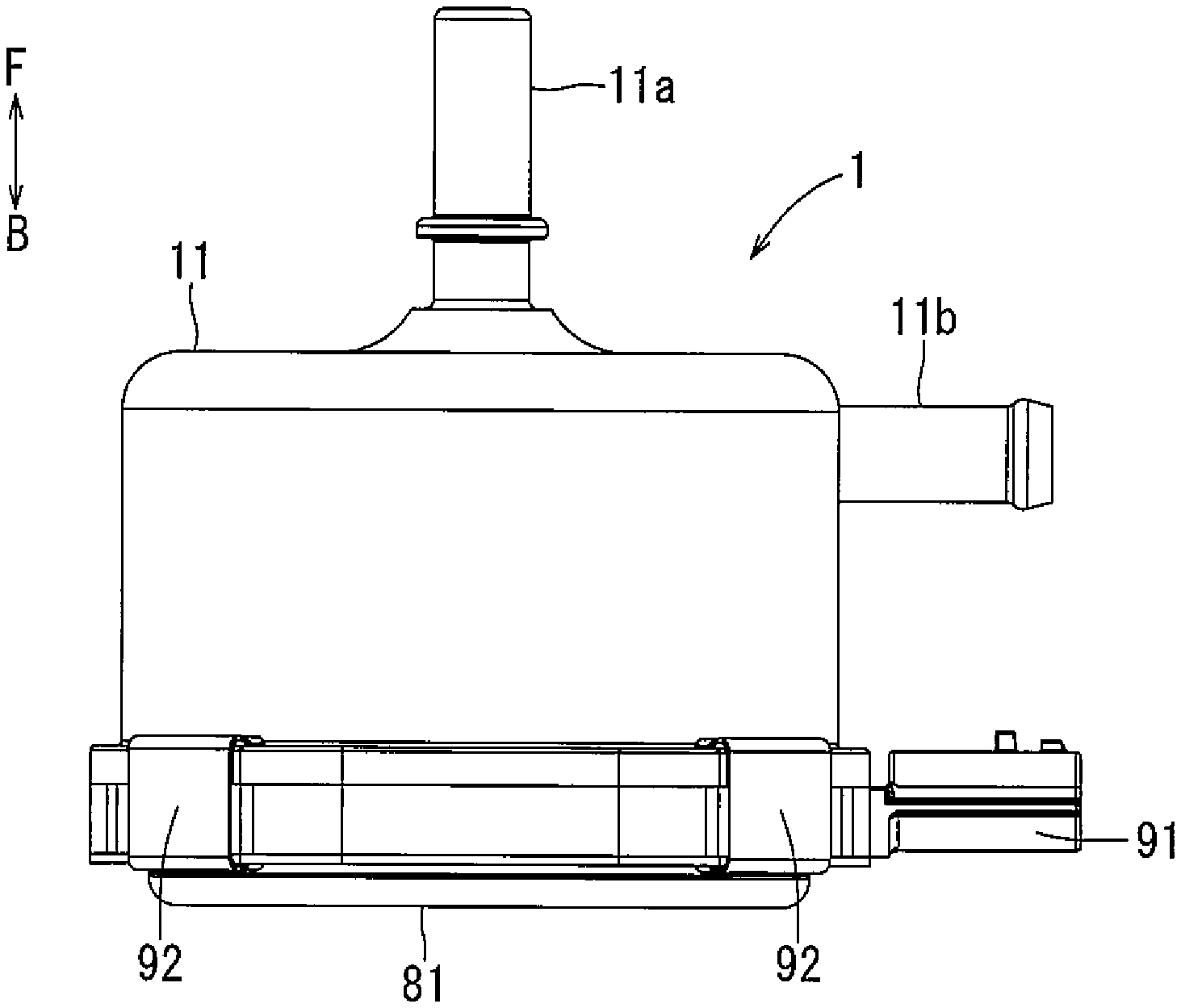
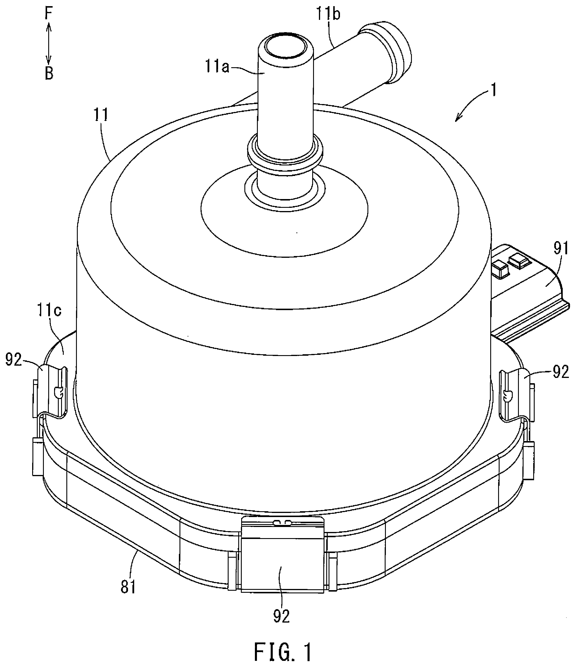
[0030] A first embodiment of the present disclosure will be described with reference to FIGS. 1 to 6. An electric pump according to the first embodiment is a purge pump 1 that is incorporated in an evaporative emission system of a vehicle equipped with an internal combustion engine, such as in an automobile. In each drawing, an arrow F defines a frontward direction of the purge pump 1, and an arrow B defines a rearward direction thereof.
[0031] As shown in FIG. 4, the purge pump 1 includes an impeller 20 and a brushless motor 45. The impeller 20 is coupled to a rotation shaft 41 of the brushless motor 45. The brushless motor 45 includes a rotor 40 and a stator 50. The rotor 40 is composed of magnetic members, such as permanent magnets. The stator 50 includes a stator core 51 and stator coils 52.
[0032] The brushless motor 45 and the impeller 20 are covered with a front cover 11 and a stator body 12, such that the brushless motor 45 and the impeller 20 are housed in an interior space formed by the front cover 11 and the stator body 12. That is, each of the front cover 11 and the stator body 12 serves as a housing member forming the interior space for the impeller 20 and the brushless motor 45. The interior space defined by the front cover 11 and the stator body 12 is divided by a partition plate 30 into a front-side space and a rear-side space. The front-side space houses the impeller 20 therein and is referred to herein as "pump chamber" The rear-side space houses the stator 50 and the rotor 40 therein and is referred to herein as "motor chamber" The stator body 12 may be made from a resin material by insert molding to integrally include a molded part 53 integrated with the stator core 51 and the stator coils 52. That is, a part of the stator body 12 serves as the housing member, and another part of the stator body 12, for example the molded part 53, corresponds to a part of the stator 50.
[0033] As shown in FIGS. 1 to 4, in this embodiment, the front cover 11 has a stepped hollow cylindrical shape with a front plate narrowing a front opening thereof and may be made from a resin material. The front cover 11 includes an inlet port 11a and an outlet port 11b. The inlet port 11a extends frontward from the front plate of the front cover 11, such that the inlet port 11a is coaxially aligned with the impeller 20. The outlet port 11b extends outward from an outer circumference of the front cover 11, along a plane oriented perpendicular to the axis of the inlet port 11a. More specifically, the outlet port 11b extends in the tangential direction from the outer periphery of the impeller 20. Thus, when the impeller 20 is rotated, the purge pump 1 suctions fuel vapor from the evaporative emission system (not shown) via the inlet port 11a and then discharges it from the outlet port 11b for supplying the fuel vapor to the internal combustion engine (not shown).
[0034] The partition plate 30 may be made from a metal material exhibiting heat conductivity and electric conductivity, and includes a bearing support part 31, an outer pipe part 32, and an elastic part 33. The outer pipe part 32 has a hollow cylindrical shape and is fitted within the hollow cylindrical portion of the front cover 11 surrounding the stator 50 in a radial direction perpendicular to the rotation shaft 41. The bearing support part 31 has a hollow cylindrical shape. The elastic part 33 has an annular plate shape extending radially from a front end of the bearing support part 31 to a front end of the outer pipe part 32. The bearing support part 31 receives bearings 42 therein and supports the outer circumferences of the bearings 42. The bearings 42 are disposed between the impeller 20 and the rotor 40 in the front-rear direction and rotatably support the rotation shaft 41.
[0035] The bearing support part 31 is coupled to the outer pipe part 32 via the elastic part 33. The elastic part 33 is configured to be elastically deformed when vibrations are transmitted from the rotation shaft 41 to the elastic part 33 via the bearing support part 31. More specifically, the elastic part 33 has a shape, for instance a relatively thin flat shape, which more easily deforms compared with the bearing support part 31 and the outer pipe part 32. That is, the elastic part 33 has a bending rigidity that is less than that of the bearing support part 31 and the outer pipe part 32. Because the elastic part 33 is shaped and configured to achieve the low bending rigidity, complicated structures of the partition plate 30 can be avoided.
[0036] Due to the foregoing configuration, when the heat generated by the bearings 42 is transmitted to the elastic part 33 via the bearing support part 31, the heat is transmitted from the elastic part 33 to the fluid being moved by the impeller 20. In addition, the outer pipe part 32 can reduce and/or prevent leakage of noise (e.g., acoustic waves) emitted from the brushless motor 45, and more specifically the stator coils 52. Further, when vibrations of the rotation shaft 41 are transmitted to the elastic part 33, the elastic part 33 is elastically deformed so as to absorb and thereby reduce the vibrational energy. Thus, pulsations in the discharge pressure of the purge pump 1, which are caused by vibrations of the rotation shaft 41, can be reduced. Meanwhile, the partition plate 30 has a high bending rigidity part near the outer pipe part 32 and in rear of a volute part 21 radially outside the impeller 20. Thus, even if the fluid pressure in the volute part 21 becomes high, the amount of deflection of the partition plate 30 will be relatively small. Accordingly, the distance between the impeller 20 and the partition plate 30 can be kept at nearly a constant value, thereby further reducing generation of the pulsations in the discharge pressure of the purge pump 1.
[0037] The partition plate 30 includes a flange part 30a extending radially outward from a rear end of the outer pipe part 32. The front cover 11 also include a flange part 11c extending radially outward from a rear end of the cylindrical portion of the front cover 11 and bending rearward. The flange part 30a is held between an inner circumference of the flange part 11c of the front cover 11 and a front surface of a flange part 12a formed at an outer periphery of the stator body 12.
[0038] As shown in FIG. 5, the front cover 11 includes a concave part 11d recessed from an inner circumference thereof. The concave part 11d includes a first support surface 11e facing rearward and a first sealing surface 11f facing radially inward. As shown in FIG. 4, the stator body 12 includes a convex part 12b projecting forward from the front surface of the flange part 12a. As shown in FIG. 5, the convex part 12b includes a second support surface 12c facing forward and a second sealing surface 12d facing radially outward. The convex part 12b of the stator body 12 is disposed to face the concave part 11d such that the first support surface 11e and the second support surface 12c face each other, and further, such that the first sealing surface 11f and the second sealing surfaces 12d face each other. The concave part 11d and the convex part 12b define a space 13 including a bent part 13a that essentially divides the first support surface 11e and the first sealing surface 11f. The bent part 13a also essentially divides the second support surface 12c from the second sealing surface 12d. The first support surface 11e and the second support surface 12c directly support the flange part 30a of the partition plate 30 therebetween, such that a leading edge of the flange part 30a is disposed in the bent part 13a. Meanwhile, the first sealing surface 11f and the second sealing surface 12d directly support an O-ring 71 therebetween. The O-ring 71 functions as a sealing member to seal the space 13 between the front cover 11 and the stator body 12.
[0039] As described above, the convex part 12b and the concave part 11d support the flange part 30a of the partition plate 30 and hold the O-ring 71. However, these components are being supported and held at positions different from each other. Thus, the partition plate 30 supporting the bearings 42 is stably supported and held between the support surfaces 11e, 12c without being influenced by the O-ring 71. Thus, the impeller 20 supported by the partition plate 30 via the bearing 42 can be stabilized at a predetermined position. Further, the partition plate 30 can decrease vibrations, which are generated by rotation of the rotor 40, of the rotation shaft 41 so as to reduce the pulsations in the discharge pressure of the purge pump 1.
[0040] The O-ring 71 is held between the front cover 11 and the stator body 12. The partition plate 30 is disposed in a sealed space formed by the front cover 11, the stator body 12, and the O-ring 71. Thus, both the pump chamber and the motor chamber can be sealed by a single O-ring 71. Further, due to the simple configuration of the space 13, support of the partition plate 30 and sealing by the O-ring 71 can be independent of each other.
[0041] As shown in FIG. 6, in this embodiment, the stator 50 has six poles. More specifically, three of the stator coils 52 are assigned with the U-phase, V-phase, and W-phase of the three-phase current that is applied from a driving circuit (not shown). The other three stator coils 62 are connected in series to the U-phase, V-phase, and W-phase stator coils 62, respectively. The stator coils 62 are arranged in the circumferential direction. The molded part 53 of the stator body 12 integrally couples the stator core 51 with the stator coils 52, so as to maintain a positional relationship between the stator core 51 and the stator coils 52. The rotor 40 is rotatably disposed at a center of the circumferentially arranged stator coils 52. The stator body 12 integrally includes spacers 12f for maintaining separation of the stator core 51 and the outer pipe part 32. The spacers 12f are uniformly circumferentially spaced and are disposed outside the stator core 51 in the radial direction perpendicular to the axis of the rotation shaft 41. Due to this configuration, circumferentially spaced curved spaces 12g are formed between the stator core 51 and the outer pipe part 32 such that the stator core 51 is exposed to the curved spaces 12g.
[0042] As shown in FIG. 4, the flange part 30a of the partition plate 30 is held between the flange part 11c of the front cover 11 and the flange part 12a of the stator body 12. The stator body 12 includes a projecting strip 12e protruding rearward from a rear surface thereof. The rear side of the stator body 12 is provided with a rear cover 81 that functions as a housing member. The rear cover 81 is made of an electrically conductive material and has a hollow shape having an opening part facing forward. The rear cover 81 includes a groove 81a at an edge of the opening part. The projecting strip 12e of the stator body 12 is loosely fitted in the groove 81e of the rear cover 81. The gap between the projecting strip 12e and the groove 81e is filled with a seal member 72 formed by injecting a liquid seal agent into the gap and then hardening the agent. Here, the stator body 12 integrally includes a connector 91 having a substantial hollow rectangular column shape. The connector 91 protrudes rearward at a rear portion of the stator body 12 such that an interior space of the connector 91 extends radially outward. The projecting strip 12e extends along an outer surface of the connector 91 at a rearward position. The seal member 72 also seals a gap formed between the connector 91 and the rear cover 81.
[0043] As shown in FIG. 3, four clamps 92 are attached to an outer circumference of the purge pump 1. As shown in FIG. 4, the clamps 92 engage with a front surface of the flange part 11c of the front cover 11 and a rear surface of a flange part 81b of the rear cover 81, so as to fixably secure the front cover 11 and the rear cover 81 to each other.
[0044] In an assembly process, the impeller 20 and the rotor 40 are attached to the partition plate 30 by the rotation shaft 41 and the bearings 42. They are then inserted into the front cover 11 from the rear. Next, the stator body 12 and the rear cover 81 are attached to the front cover 11 from the rear. The assembly of these components of the purge pump 1 carried out in one direction, e.g. in the forward direction, simplifies and eases the assembly process, thereby offering the potential to enhance productivity.
[0045] A circuit board 60 is fixed to the rear surface of the stator body 12 and is covered by the rear cover 81. The circuit board 60 has a plate shape extending in the radial direction and is within the outer circumference of the outer pipe part 32 of the partition plate 30 from a plan view along the axial direction. The circuit board 60 includes circuit elements (not shown), such as an integrated circuit (IC) chip, on a front or rear surface thereof such that the circuit elements form an electric circuit of the circuit board 60. The circuit board 60 is provided with coil terminals 61, a power terminal 62, and a grounding terminal 63 that extend forward from the circuit board 60 and penetrate the circuit board 60 rearward to be connected with the electric circuit of the circuit board 60. The circuit board 60 may be integrated with the stator body 12.
[0046] The coil terminals 61 are electrically coupled to the stator coils 52. The grounding terminal 63 contacts an inward surface of the outer pipe part 32 of the partition plate 30 and is connected with the rear cover 81. The grounding terminal 63 is also electrically coupled to an external grounding terminal (not shown) housed in the connector 91. The power terminal 62 supplies electrical power to the electric circuit of the circuit board 60. In this embodiment, the power terminal 62 extends from the circuit board 60 and into the connector 91 and is configured to be connected to an external power source to serve as a "connector terminal." The connector 91 may be separated formed from the stator body 12.
[0047] Because the circuit elements of the circuit board 60 are rearward of the partition plate 30 and are positioned within the radial periphery of the motor chamber defined by the outer pipe part 32 of the partition plate 30, acoustic waves and vibrations emitted forward from the circuit board 60 and the stator coils 52 can be absorbed by the partition plate 30. In addition, the rear side of the circuit board 60 is covered with the rear cover 81, so that acoustic waves and vibrations emitted rearward from the circuit board 60 and the stator coils 52 can be absorbed by the rear cover 81.
[0048] A second embodiment will be described. The second embodiment corresponds to the first embodiment with some differences relating to positions of the coil terminals 61. Thus, while some of the differences will be described in greater detail below, similar configurations will not be described in the interest of conciseness.
[0049] As shown in FIG. 7, each coil terminal 61 of the second embodiment extends forward from the circuit board 60 and penetrates the stator body 12. The front portion of the coil terminals 61 are each disposed in the curved spaces 12g formed radially outside the stator core 51. The front end of each coil terminal 61 is connected to the corresponding front side of the stator coil 52.
[0050] In the second embodiment, the stator coils 52 are connected with the electric circuit of the circuit board 60 via the coil terminals 61 disposed radially outside the stator coils 52. Each coil terminal 61 is connected to the corresponding stator coil 52 via a side of the coil terminal 61 further from the circuit board 60. Accordingly, the coil terminals 61 are not disposed between the stator coils 52 and the circuit board 60. Therefore, the circuit board 60 can be disposed nearer the stator coils 52, reducing the size of the purge pump 1 in the axial direction of the rotation shaft 41.
[0051] Each coil terminal 61 is disposed radially outside the stator 50 and partially overlaps the stator 50 in the radial direction of the rotation shaft 41. For instance, a part of each coil terminal 61 is in a space radially outside of the stator 50 in the curved spaces 12g. Thus, the axial size of the purge pump 1 is not increased by the coil terminals 61. In addition, it is not necessary to provide additional spaces for the coil terminals 61, so that an increase in the radial size of the purge pump 1 can be avoided.
[0052] Further, the coil terminals 61 receive heat from the stator coils 52 and radiate the heat toward the outer pipe part 32 of the partition plate 30. Thus, the heat of the stator coils 52 is radiated to the outside via the outer pipe part 32 of the partition plate 30, thereby offering the potential to reduce thermal damage to the stator 50.
[0053] A third embodiment will be described. The third embodiment corresponds to the first embodiment with some differences. Thus, while some of the differences will be described in greater detail below, similar configurations will not be described in the interest of conciseness. For instance, the purge pump 1 of the third embodiment includes a rear cover 82 and a seal member 73, instead of the rear cover 81 and the O-ring 71 of the first embodiment.
[0054] As shown in FIG. 8, the rear cover 82 includes a flange part 82b extending forward from a radially outer periphery of the rear cover 82. The flange part 82b extends forward so as to be radially outside the flange part 11c of the front cover 11, e.g., by surrounding an outer circumference of the flange part 11c of the front cover 11. The flange part 82b of the rear cover 82 may also be positioned so as to overlap the flange part 12a of the stator body 12. At least a majority of the portion of the coil terminal 61 is not overlapped by the outer pipe part 32 in the radial direction.
[0055] The front cover 11 is coupled to the rear cover 82 by the clamps 92 in a state where the flange part 12a of the stator body 12 is held between the front cover 11 and the rear cover 82. However, it may be difficult to secure clamps 92 attached to a position where the flange part 82b of the rear cover 82 is positioned radially outside the flange part 11c of the front cover 11. So, the flange part 82b may have some cut portions, e.g. notches, such that the clamps 92 can engage with the flange part 11c of the front cover 11 and can engage an outer periphery 82c of a bottom portion of the rear cover 82 at the cut portions.
[0056] The flange part 12a of the stator body 12 includes a convex portion protruding from a front surface thereof. The flange part 11c of the front cover 11 includes a concave portion recessed from a rear surface thereof. The convex portion of the flange part 12a is loosely fitted in the concave portion of the flange part 11c. A gap between the concave portion of the flange part 11c and the convex portion of the flange part 12a is filled with a seal member 73 formed by injecting a liquid sealing agent into the gap and then hardening the agent. Similarly, the seal member 72 is provided between the flange part 12a of the stator body 12 and the outer periphery 82c of the bottom portion of the rear cover 82.
[0057] In accordance with the third embodiment, the rear opening of the outer pipe part 32 of the partition plate 30 is covered with the rear cover 82. That is, the outer pipe part 32 of the partition plate 30 opens toward an interior space of the rear cover 82. Thus, when acoustic waves and vibrations are emitted by the stator 50 and leak from the rear opening of the outer pipe part 32, the rear cover 82 can prevent leakage of the acoustic waves and vibrations to the outside. Further, acoustic waves and vibrations emitted by the coil terminals 61 in a direction perpendicular to the coil terminals 61 can be absorbed by the flange part 82b of the rear cover 82.
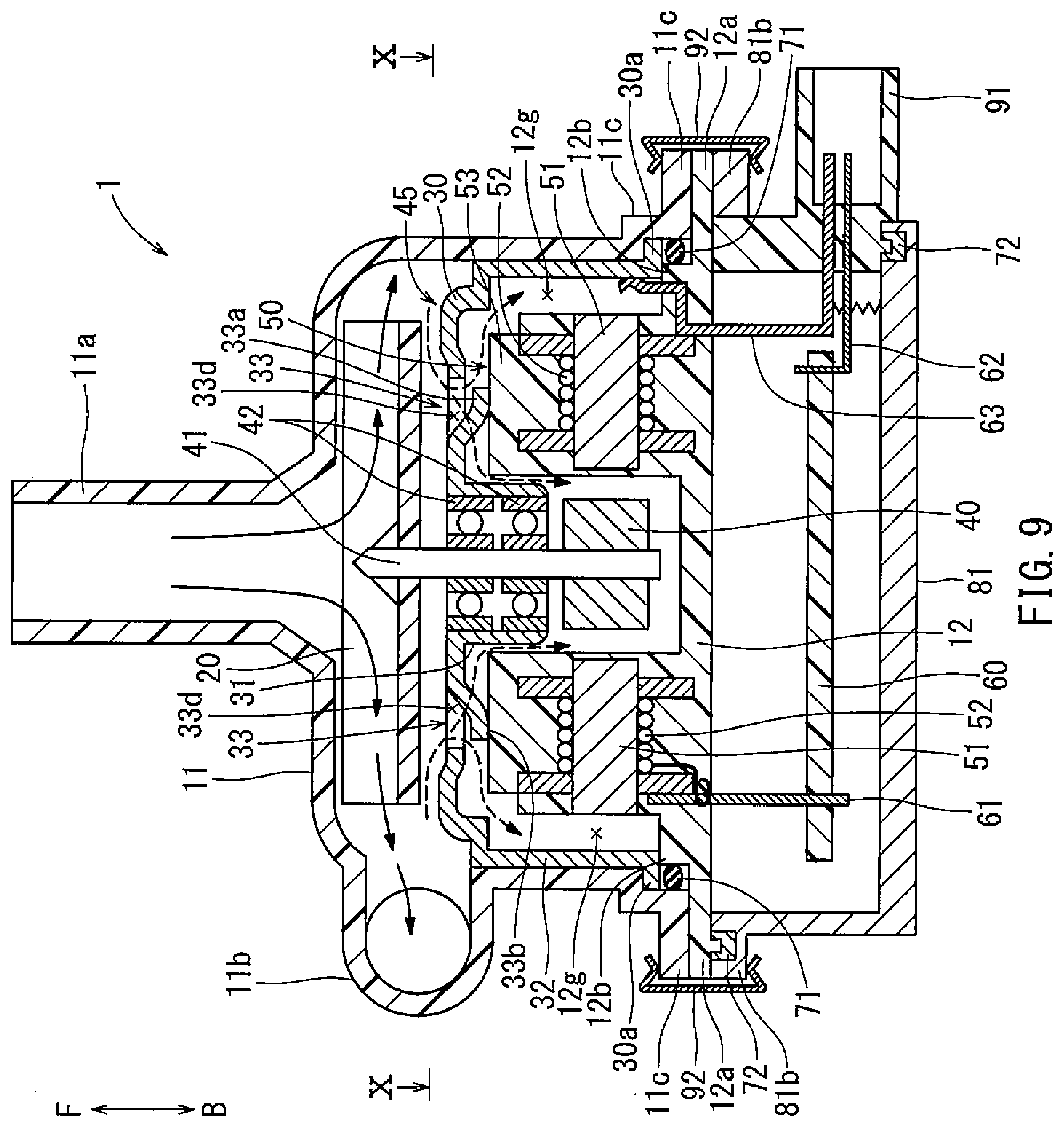
[0058] A fourth embodiment will be described. The fourth embodiment corresponds to the first embodiment with some differences. Thus, while some of the differences will be described in greater detail below, similar configurations will not be described in the interest of conciseness. For example, the elastic part 33 of the fourth embodiment includes support parts 33a.
[0059] As shown in FIGS. 9 and 10, the elastic part 33 includes four support parts 33a arranged circumferentially between the bearing support part 31 and the outer pipe part 32. Each support part 33a may be formed to be elastically deformable by cutting a part of a front plate portion of the partition plate 30 and bending the part toward the motor chamber. As shown in FIG. 9, a leading edge 33b of each support part 33a contacts a front surface of the stator body 12. As shown in FIGS. 10 and 11, each support part 33a includes a guide surface 33c extending in a flow direction of a fluid forced by the impeller 20 along the support part 33a of the partition plate 30, which is shown by dashed arrows in FIGS. 10 and 11. Accordingly, the leading edges 33b are positioned on a downstream side of the fluid flow. As a result of cutting and bending the partition plate 30 to form the support parts 33a, the partition plate 30 includes an opening 33d in front of the support parts 33a.
[0060] As shown in FIGS. 10 and 11, each support part 33a actually extends in a circumferential direction about the axis of the rotation shaft 41 and bends rearward. In FIG. 9, solid arrows show a flow of the fluid, e.g. air containing fuel vapor, which is suctioned via the inlet port 11a and then is discharged from the outlet port 11b by the impeller 20. Meanwhile, dashed arrows show a flow of a part of the fluid, which flows into the motor chamber through the openings 33d.
[0061] In accordance with the fourth embodiment, the leading edges 33b of the support parts 33a contact the front surface of the molded body 53 of the stator body 12. So, the partition plate 30 is biased forward due to the elastic force of the support parts 33a, when the flange part 30a of the partition plate 30 is engaged with the flange part 11c of the front cover 11. Thus, the partition plate 30 can be positioned at a predetermined position with respect to the stator 50. As a result, the impeller 20 supported by the partition plate 30 via the bearings 42 and the rotation shaft 41 can be positioned at the predetermined position with respect to the stator 50. In addition, when vibrations are transmitted from the rotation shaft 41 to the support parts 33a, the support parts 33a elastically deform so as to absorb the vibrational energy. Further, because the fluid flows from the pump chamber into the motor chamber through the openings 33d of the partition plate 30, the partition plate 30 and components of the brushless motor 45 can be cooled. For example, the fluid flow includes a first flow passing radially outside the bearings 42 to a space between the rotor 40 and the stator body 12 and a second flow toward the curved spaces 12g. Thus, the bearings 42, the stator body 50 and the partition plate 30 can be efficiently cooled.
[0062] The guide surface 33c of each support part 33a extends along the direction of the fluid flow generated by the impeller 20. Thus, the fluid flows smoothly along each guide surface 33c from the pump chamber into the motor chamber through the openings 33d, so that the motor can be efficiently cooled by the fluid. Further, the partition plate 30 includes four support parts 33a and is supported on the stator body 12 by the support parts 33a, each radially positioned outside the bearings 42. Thus, the partition plate 30 can be stably supported on the stator body 12. To ensure the stable support of the partition plate 30 on the stator body 12, the number of the support parts 33a is preferably equal to or greater than three.
[0063] A fifth embodiment will be described. The fifth embodiment corresponds to the fourth embodiment with some differences. Thus, while some of the differences will be described in greater detail below, similar configurations will not be described in the interest of conciseness. For example, in the fifth embodiment, one of the bearings 42 is disposed frontward of the rotor 40, and the other is disposed rearward of the rotor 40.
[0064] As shown in FIG. 12, the bearings 42 support the rotation shaft 41 on both sides of the rotor 40. The rear-side bearing 42 is directly affixed to the stator body 12. Thus, the rotation shaft 41 is supported so as to stabilize the position of the impeller 20. As a result, vibration of the rotation shaft 41 can be suppressed, thereby decreasing pulsations in the discharge pressure of the purge pump 1.
[0065] A sixth embodiment will be described. The sixth embodiment corresponds to the fourth embodiment with some differences. Thus, while some of the differences will be described in greater detail below, similar configurations will not be described in the interest of conciseness. For example, the elastic part 33 of the sixth embodiment includes support parts 33e, instead of the support parts 33a of the fourth embodiment.
[0066] As shown in FIGS. 13 and 14, the elastic part 33 includes the support parts 33e near the outer pipe part 32. Each support part 33e may have almost the same shape as each support part 33a of the fourth embodiment. However, the leading edges 33f of the support parts 33e contact corresponding front surfaces of the spacers 12f Each support part 33e may actually be formed by cutting a part of the partition plate 30 along an inner periphery of the outer pipe part 32 and bending the part rearward. Thus, each support part 33e extends in the circumferential direction about the axis of the rotation shaft 41 and slopes rearward, similar to the support parts 33a shown in FIGS. 10 and 11. The partition plate 30 includes openings 33g in front of the support parts 33e. Each opening 33g is formed by cutting and bending rearward the corresponding support part 33e.
[0067] In accordance with the sixth embodiment, the openings 33g are disposed backward of the volute part 21 and located radially outside the impeller 20. Thus, the fluid easily flows from the volute part 21 into the motor chamber through the openings 33g, so as to cool the components of the brushless motor 45 more efficiently.
[0068] A seventh embodiment will be described. The seventh embodiment corresponds to the fifth embodiment with some differences. Thus, while some of the differences will be described in greater detail below, similar configurations will not be described in the interest of conciseness. For example, in the seventh embodiment, the bearing support part 31 of the partition plate 30 is configured to house the rotor 40 and the bearings 42 therein. The partition plate 30 is made from a nonmagnetic material.
[0069] As shown in FIG. 15, the bearing support part 31 has a hollow cylindrical shape with a closed rear end such that the bearings 42 and the rotor 40 are housed therein. The bearing support part 31 supports the outer circumferences of the bearings 42 and is disposed along an inner circumference of the stator 50. Thus, the bearing support part 31 can transmit heat from the bearings 42 and the stator 50 to the outer pipe part 32, thereby radiating heat from the outer pipe part 32 toward the outside of the purge pump 1.
[0070] The present teaching is not limited to the above-described embodiments and can be modified in various ways while being within the scope of the teaching. For example, the present teaching can be applied to various pumps instead of the purge pump 1 installed on the vehicle. Various motors can be used instead of the brushless motor 45. For example, it is possible to use a motor including stator coils that are circumferentially arranged and an annular rotor disposed around the stator coils.
* * * * *
D00000
D00001
D00002
D00003
D00004
D00005
D00006
D00007
D00008
D00009
D00010
D00011
D00012

XML
uspto.report is an independent third-party trademark research tool that is not affiliated, endorsed, or sponsored by the United States Patent and Trademark Office (USPTO) or any other governmental organization. The information provided by uspto.report is based on publicly available data at the time of writing and is intended for informational purposes only.
While we strive to provide accurate and up-to-date information, we do not guarantee the accuracy, completeness, reliability, or suitability of the information displayed on this site. The use of this site is at your own risk. Any reliance you place on such information is therefore strictly at your own risk.
All official trademark data, including owner information, should be verified by visiting the official USPTO website at www.uspto.gov. This site is not intended to replace professional legal advice and should not be used as a substitute for consulting with a legal professional who is knowledgeable about trademark law.