Percussive Drill String Assemblies And Systems And Methods Of Using Same
HOGAN; JEFFREY ; et al.
U.S. patent application number 16/521196 was filed with the patent office on 2020-03-19 for percussive drill string assemblies and systems and methods of using same. The applicant listed for this patent is BLY IP INC.. Invention is credited to CHRISTOPHER L. DRENTH, JEFFREY HOGAN, TUSHAR MATKAR.
| Application Number | 20200087994 16/521196 |
| Document ID | / |
| Family ID | 69773839 |
| Filed Date | 2020-03-19 |


View All Diagrams
| United States Patent Application | 20200087994 |
| Kind Code | A1 |
| HOGAN; JEFFREY ; et al. | March 19, 2020 |
Percussive Drill String Assemblies And Systems And Methods Of Using Same
Abstract
A percussive drill string assembly including a drill bit and a drill rod. The drill bit has a body having: a circumferential wall; a crown extending distally from the circumferential wall; and a threaded portion extending proximally from the circumferential wall. The threaded portion has an outer surface that defines at least one thread having a tapered thread profile. The drill rod has a box end portion having an inner surface that defines: a receptacle configured to receive the threaded portion of the bit; and at least one thread having a tapered profile complementary to the tapered thread profile of the threaded portion of the bit.
| Inventors: | HOGAN; JEFFREY; (Brampton, CA) ; DRENTH; CHRISTOPHER L.; (Burlington, CA) ; MATKAR; TUSHAR; (Mississauga, CA) | ||||||||||
| Applicant: |
|
||||||||||
|---|---|---|---|---|---|---|---|---|---|---|---|
| Family ID: | 69773839 | ||||||||||
| Appl. No.: | 16/521196 | ||||||||||
| Filed: | July 24, 2019 |
Related U.S. Patent Documents
| Application Number | Filing Date | Patent Number | ||
|---|---|---|---|---|
| 62732209 | Sep 17, 2018 | |||
| Current U.S. Class: | 1/1 |
| Current CPC Class: | E21B 17/00 20130101; E21B 1/00 20130101; E21B 10/003 20130101; E21B 10/36 20130101; E21B 17/0426 20130101; E21B 10/42 20130101; E21B 17/042 20130101; E21B 10/60 20130101 |
| International Class: | E21B 17/042 20060101 E21B017/042; E21B 10/36 20060101 E21B010/36; E21B 10/42 20060101 E21B010/42 |
Claims
1. A single-rod percussive drill string assembly having a longitudinal axis and comprising: a drill bit having: a body having: a circumferential wall; and a crown extending distally from the circumferential wall; and a threaded portion extending proximally from the circumferential wall, wherein the threaded portion has an outer surface that defines at least one thread having a tapered thread profile; and a drill rod having: a box end portion having an inner surface that defines: a receptacle configured to receive the threaded portion of the bit; and at least one thread having a tapered profile complementary to the tapered thread profile of the threaded portion of the bit, wherein the drill rod is the only drill rod of the percussive drill string assembly.
2. The percussive drill string assembly of claim 1, wherein the box end portion of the drill rod defines a distal end of the drill rod and has an outer surface, wherein at least a portion of the outer surface of the box end portion is inwardly tapered moving proximally from the distal end.
3. The percussive drill string assembly of claim 1, wherein the circumferential wall and the threaded portion of the drill bit cooperate to define an interior space extending along the longitudinal axis of the percussive drill string assembly.
4. The percussive drill string assembly of claim 3, wherein the drill rod comprises a mid-body portion that extends proximally from the box end portion, and wherein the mid-body portion has an inner surface that cooperates with the circumferential wall and the threaded portion of the drill bit to further define the interior space.
5. The percussive drill string assembly of claim 3, wherein the threaded portion of the drill bit defines a proximal end of the drill bit and wherein the body of the drill bit defines a shoulder that is configured to abut a distal end of the drill rod, and wherein the drill bit comprises: a water slot defined by the proximal end of the drill bit and extending radially from the interior space to the outer surface of the threaded portion; and/or a water slot defined by the shoulder and extending radially outwardly to an exterior surface of the drill bit.
6. The percussive drill string assembly of claim 3, wherein the crown of the body of the drill bit is a full-face crown.
7. The percussive drill string assembly of claim 6, wherein the crown of the body of the drill bit defines a plurality of bores in fluid communication with the interior space.
8. The percussive drill string assembly of claim 3, wherein the circumferential wall of the body of the drill bit defines at least one bore in fluid communication with the interior space.
9. The percussive drill string assembly of claim 1, wherein the circumferential wall of the body of the drill bit has an outer surface that defines at least one axial channel.
10. The percussive drill string assembly of claim 2, wherein the outer surface of the box end portion of the drill rod defines a plurality of axial slots.
11. The percussive drill string assembly of claim 10, wherein the circumferential wall of the body of the drill bit has an outer surface that defines at least one axial channel, and wherein at least one axial slot of the plurality of axial slots is axially aligned with a corresponding axial channel of the body of the drill bit.
12. The percussive drill string assembly of claim 10, wherein the axial slots are proximally tapered.
13. The percussive drill string assembly of claim 10, wherein the box end portion of the drill rod has an axial length, and wherein at least one axial slot of the plurality of axial slots has an axial length that is greater than 60% of the axial length of the box end portion.
14. The percussive drill string assembly of claim 4, wherein the mid-body portion of the drill rod is welded to the box end portion of the drill rod.
15. The percussive drill string assembly of claim 4, wherein the mid-body and box end portions of the drill rod are forged as a single piece.
16. The percussive drill string assembly of claim 1, wherein the drill bit has a gauge diameter, wherein the circumferential wall and the crown of the body of the drill bit have a combined axial length, and wherein a ratio between the combined axial length of the crown and the body of the drill bit and the gauge diameter of the drill bit is less than 0.7.
17. The percussive drill string assembly of claim 1, wherein the crown of the body of the drill bit has a staged profile.
18. The percussive drill string assembly of claim 10, wherein the box end portion of the drill rod has an outer diameter that circumscribes a cylinder, and wherein the plurality of axial slots are inwardly recessed from the outer diameter and inwardly tapered moving proximally from the distal end.
19. The percussive drill string assembly of claim 1, wherein the drill rod comprises at least one back face defining a cutting profile.
20. A drilling system comprising the percussive drill string assembly of claim 1, wherein the drilling system is a single-pass system that does not comprise an extension or an additional drill rod.
21. A drilling method comprising: penetrating a formation using a single-rod percussive drill string assembly having a longitudinal axis and comprising: a drill bit having: a body having: a circumferential wall; and a crown extending distally from the circumferential wall; and a threaded portion extending proximally from the circumferential wall, wherein the threaded portion has an outer surface that defines at least one thread having a tapered thread profile; and a drill rod having: a box end portion having an inner surface that defines: a receptacle configured to receive the threaded portion of the bit; and at least one thread having a tapered profile complementary to the tapered thread profile of the threaded portion of the bit wherein the drill rod is the only drill rod of the percussive drill string assembly.
Description
CROSS-REFERENCE TO RELATED APPLICATIONS
[0001] This application claims the benefit of the filing date of U.S. Provisional Patent Application No. 62/732,209, filed Sep. 17, 2018, which is hereby incorporated by reference herein in its entirety for all purposes.
FIELD
[0002] The disclosed invention relates to percussive drill string assemblies, and, in particular, to single-rod percussive drill string assemblies.
BACKGROUND
[0003] Conventionally, percussive bits are used to quickly penetrate a variety of formations. In drifting, tunneling, and bolting applications, a single-rod percussive drilling assembly can be used. However, such single-rod assemblies are frequently associated with inadequate advance and penetration rates, leading to misalignment (incorrect hole initiation), deviation/divergence of the hole (holes lacking desired straightness or smoothness), drill rod tip-off or deflection (in response to collaring), and deficiencies in hole-spotting. In order to avoid these issues, there is a need for single-rod drilling assemblies that provide increased advance and penetration rates to provide improved strength, rod life, energy transmission, and flushing, thereby resulting in more successful drilling operations.
SUMMARY
[0004] Described herein, in various aspects, is a percussive drill string assembly having a longitudinal axis. The percussive drill string assembly can include a drill bit and a drill rod. The drill bit can have a body. The body of the drill bit can have: a circumferential wall; a crown extending distally from the circumferential wall; and a threaded portion extending proximally from the circumferential wall. The threaded portion can have an outer surface that defines at least one thread having a tapered thread profile. The drill rod can have a box end portion having an inner surface. The inner surface of the box end portion can define: a receptacle configured to receive the threaded portion of the body of the bit; and at least one thread having a tapered profile complementary to the tapered thread profile of the threaded portion of the body of the bit.
[0005] Also described are systems and methods of using the disclosed drill string assemblies.
DESCRIPTION OF THE DRAWINGS
[0006] FIG. 1A is a perspective view of an exemplary drill string assembly as disclosed herein. FIG. 1B is a cross-sectional view of the drill string assembly of FIG. 1A.
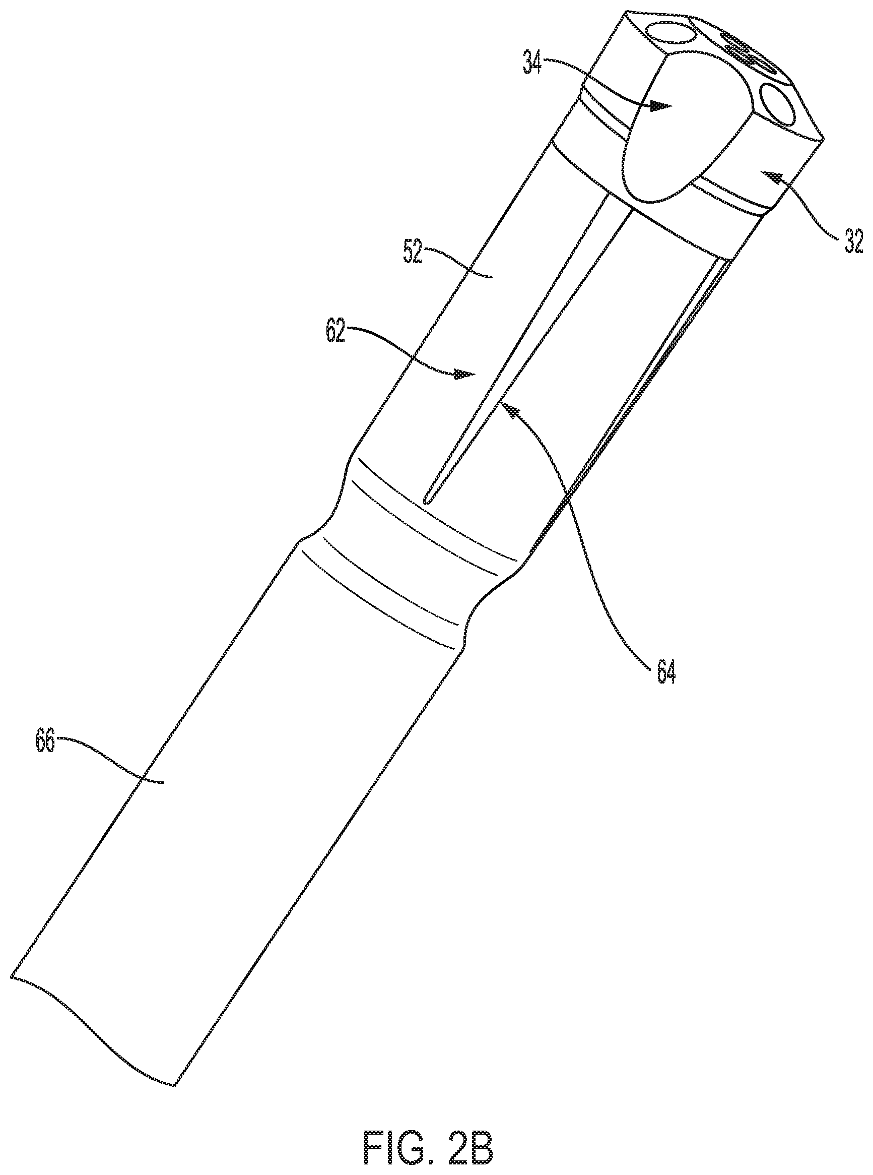
[0007] FIG. 2A is a perspective view of an exemplary drill string assembly having a drill rod with axial slots as disclosed herein. FIG. 2B is a perspective view of an exemplary drill string assembly having a drill rod formed of round steel and defining axial slots as disclosed herein.
[0008] FIG. 3 is a perspective view of an exemplary drill string assembly having a crown with projecting buttons and a drill rod with axial slots as disclosed herein.
[0009] FIG. 4A is a perspective view of an exemplary drill bit having a body 22 and a proximal threaded portion as disclosed herein. FIG. 4B is a perspective view of an exemplary drill bit having a water slot in an alternative location.
[0010] FIG. 5A is a side elevational view of an exemplary drill bit having a staged profile as disclosed herein. FIG. 5B is a top plan view of the drill bit of FIG. 5A.
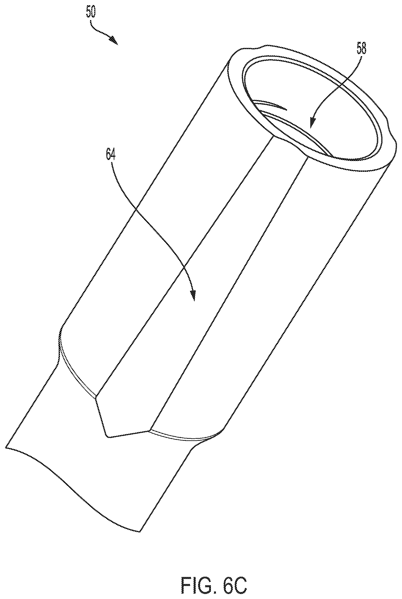
[0011] FIG. 6A is a perspective view of an exemplary drill rod having a cylindrical outer diameter and tapered axial slots as disclosed herein. FIG. 6B is a cross-sectional view of the drill rod of FIG. 6A. FIG. 6C is a perspective view of another exemplary drill rod having a cylindrical outer diameter and tapered axial slots as disclosed herein.
[0012] FIG. 7 is a perspective view of an exemplary drill rod having angled axial slots as disclosed herein.
[0013] FIG. 8A is a perspective view of a portion of a drill rod, in accordance with embodiments disclosed herein, having cutting removal features. FIG. 8B is side view of the portion of the drill rod of FIG. 8A. FIG. 8C is a bottom view of the portion of the drill rod of FIG. 8A. FIG. 8D is a detail view of the side view of FIG. 8A.
DETAILED DESCRIPTION
[0014] The present invention now will be described more fully hereinafter with reference to the accompanying drawings, in which some, but not all embodiments of the invention are shown. Indeed, this invention may be embodied in many different forms and should not be construed as limited to the embodiments set forth herein; rather, these embodiments are provided so that this disclosure will satisfy applicable legal requirements. Like numbers refer to like elements throughout. It is to be understood that this invention is not limited to the particular methodology and protocols described, as such may vary. It is also to be understood that the terminology used herein is for the purpose of describing particular embodiments only, and is not intended to limit the scope of the present invention.
[0015] Many modifications and other embodiments of the invention set forth herein will come to mind to one skilled in the art to which the invention pertains having the benefit of the teachings presented in the foregoing description and the associated drawings. Therefore, it is to be understood that the invention is not to be limited to the specific embodiments disclosed and that modifications and other embodiments are intended to be included within the scope of the appended claims. Although specific terms are employed herein, they are used in a generic and descriptive sense only and not for purposes of limitation.
[0016] As used herein the singular forms "a", "an", and "the" include plural referents unless the context clearly dictates otherwise. For example, use of the term "a channel" can refer to one or more of such channels.
[0017] All technical and scientific terms used herein have the same meaning as commonly understood to one of ordinary skill in the art to which this invention belongs unless clearly indicated otherwise.
[0018] Ranges can be expressed herein as from "about" one particular value, and/or to "about" another particular value. When such a range is expressed, another aspect includes from the one particular value and/or to the other particular value. Similarly, when values are expressed as approximations, by use of the antecedent "about," it will be understood that the particular value forms another aspect. It will be further understood that the endpoints of each of the ranges are significant both in relation to the other endpoint, and independently of the other endpoint. Optionally, in some aspects, when values are approximated by use of the antecedent "about" or "substantially," it is contemplated that values within up to 15%, up to 10%, or up to 5% (above or below) of the particularly stated value or characteristic can be included within the scope of those aspects.
[0019] As used herein, the terms "optional" or "optionally" mean that the subsequently described event or circumstance may or may not occur, and that the description includes instances where said event or circumstance occurs and instances where it does not.
[0020] The word "or" as used herein means any one member of a particular list and also includes any combination of members of that list.
[0021] As used herein, the term "proximal" refers to a direction toward the surface of a formation (where a drill rig can be located), whereas the term "distal" refers to a direction toward the bottom or end of a drill hole, moving away from the surface of the formation. When the terms "proximal" and "distal" are used to describe system components, it is expected that during normal use of those components, the "proximal" components will be positioned proximally (closer to the surface of the formation) relative to the "distal" components and the "distal" components will be positioned distally (closer to the bottom of a drill hole) relative to the "proximal" components.
[0022] As used herein, the term "[metal]-based alloy" (where [metal] is any metal) means commercially pure [metal] in addition to metal alloys wherein the weight percentage of [metal] in the alloy is greater than the weight percentage of any other component of the alloy. Where two or more metals are listed in this manner, the weight percentage of the listed metals in combination is greater than the weight percentage of any other component of the alloy.
[0023] As used herein, the term "tungsten carbide" means any material composition that contains chemical compounds of tungsten and carbon in any stoichiometric or non-stoichiometric ratio or proportion, such as, for example, WC, W.sub.2C, and combinations of WC and W.sub.2C. Tungsten carbide includes any morphological form of this material, for example, cast tungsten carbide, sintered tungsten carbide, monocrystalline tungsten carbide, and macrocrystalline tungsten carbide.
[0024] As used herein, the term "wear-resistant" refers to a drilling tool that is not designed to erode or degrade to expose cutting material imbedded or otherwise positioned within the drilling tool. Thus, wear-resistant tools are distinguishable from--and operate in a fundamentally different way than--impregnated drilling tools that are designed to wear away to continuously expose cutting media within the drilling tools.
[0025] The following description supplies specific details in order to provide a thorough understanding. Nevertheless, the skilled artisan would understand that the apparatus and associated methods of using the apparatus can be implemented and used without employing these specific details. Indeed, the apparatus and associated methods can be placed into practice by modifying the illustrated apparatus and associated methods and can be used in conjunction with any other apparatus and techniques conventionally used in the industry.
[0026] Disclosed herein are drill string assemblies and associated systems and methods. It is contemplated that the disclosed drill string assemblies can provide one or more improvements or advantages in comparison to existing tunneling drill string assemblies, leading to increases in rod life and straighter holes. Conventionally, rod tip-off is a major problem for tunneling rods. Often, the rods are (incorrectly) used for scaling purposes, leading to dragging of the bit along rock as a hammering operation continues and resulting in undesirable loading problems that exacerbate the problem of rod failure. As further disclosed herein, it is contemplated that the disclosed drill string assemblies can provide better flushing and tip-off resistance in comparison to conventional tunneling rod assemblies. It is further contemplated that the disclosed drill string assemblies can reduce or eliminate the misuse of rods for scaling purposes.
[0027] Disclosed herein, in various aspects and with reference to FIGS. 1A-7 is a drill string assembly 10 having a longitudinal axis 12. In exemplary aspects, the drill string assembly 10 can have a drill bit 20 and a drill rod 50. The drill bit 20 can have a body 22, which can include a circumferential (annular) wall 30 and a crown 24 extending distally from the circumferential wall. The drill bit 20 can further comprise a threaded portion 40 extending proximally from the circumferential wall 30. In further aspects, the threaded portion 40 can have an outer surface that defines at least one thread 42 having a tapered thread profile. In additional aspects, the drill rod 50 can have a box end portion 52 having an inner surface 56. In these aspects, the inner surface 56 of the box end portion 52 can define a receptacle 58 configured to receive the threaded portion 42 of the bit 20. In still further aspects, the inner surface 56 of the box end portion 52 can define at least one thread 60 having a tapered profile complementary to the tapered thread profile of the threaded portion 42 of the bit 20. In exemplary aspects, it is contemplated that the tapered thread profile of the threaded portion 42 of the bit can have a taper ranging from about 1 degree to about 10 degrees relative to the longitudinal axis 12.
[0028] Optionally, it is contemplated that the drill bit 20 can be a wear-resistant drill bit. Optionally, in exemplary aspects, the drill bit 20 can be a percussive drill bit, such as a button drill bit, a blade drill bit, or a down-the-hole (DTH) hammer bit. In exemplary aspects, the drill bit 20 can be a button drill bit comprising buttons 25, such as, for example and without limitation, a rotary drag bit, a bi-cone bit, or a tri-cone bit. Such buttons can be secured to the cutting face of the bit using conventional methods. Optionally, such buttons can comprise carbide (e.g., tungsten carbide) and/or polycrystalline diamond (PCD). Alternatively, it is contemplated that buttons 25 can be integrally formed with the matrix that forms the bit 20. Although depicted as a drill bit in the Figures, it is contemplated that other wear-resistant drilling tools, such as hole reamers, back reamers, hole openers, and drill string stabilizers, can be used in place of the disclosed drill bit, in combination with the drill rod 50.
[0029] In exemplary aspects, the body 22 of the drill bit 20 can be an infiltrated body comprising a matrix and a binder. In these aspects, the matrix can comprise a hard particulate material and a plurality of abrasive particles dispersed throughout the hard particulate material. It is contemplated that the binder can secure the hard particulate material and the abrasive particles together. In exemplary aspects, the plurality of abrasive particles can comprise a plurality of diamond particles. However, it is contemplated that any conventional abrasive cutting media can be used.
[0030] In exemplary aspects, the box end portion 52 of the drill rod 50 can define a distal end 54 of the drill rod and have an outer surface 62. Optionally, in these aspects, it is contemplated that at least a portion of the outer surface 62 of the box end portion 52 can be inwardly tapered (toward the longitudinal axis 12) moving proximally from the distal end 54. It is contemplated that the combination of a drill bit with a tapered thread and a drill rod having a box end portion with a tapered outer diameter can permit use of a standard (non-cylindrical) mid-body design in the drill rod. It is further contemplated that this combination can provide for more efficient evacuation of cuttings and more drilling productivity in comparison to the use of straight couplings/rods. In exemplary aspects, at least a portion of the outer surface 62 of the box end portion 52 can be inwardly tapered at an angle ranging from about 2 degrees to about 10 degrees. Optionally, as shown in FIG. 1A, the entire outer surface 62 can have a consistent taper. Alternatively, in further aspects and as shown in FIGS. 6A-6C, the box end portion 52 of the drill rod 50 can have an outer diameter that circumscribes a cylinder. In these aspects, the box end portion 52 can comprise a plurality of axial slots 64 (further described below) that are inwardly recessed from the outer diameter and inwardly tapered moving proximally from the distal end 54. It is contemplated that these axial slots can be inwardly tapered at an angle ranging from about 2 degrees to about 10 degrees. Optionally, in some aspects, at least one axial slot 64 (optionally, each axial slot 64) of the plurality of axial slots can have a straight profile as shown in FIGS. 6A and 6C. Alternatively, in other aspects, and as shown in FIG. 7, the outer diameter of the box end portion need not circumscribe a cylinder. In these aspects, a plurality of axial slots 64 can be inwardly recessed from the outer diameter and inwardly tapered moving proximally from the distal end 54. As shown, it is contemplated that at least one axial slot 64 (optionally, each axial slot) of the plurality of axial slots can have a spiral or helical profile.
[0031] Optionally, in exemplary aspects, the plurality of axial slots 64 can be equally or substantially equally circumferentially spaced about the outer surface 62 of the box end portion 52. In one aspect, it is contemplated that the plurality of axial slots 64 can optionally be equally or substantially equally sized. Optionally, in further exemplary aspects, it is contemplated that the plurality of axial slots 64 can comprise from 2 to 16 axial slots or, more practically, from 2 to 6 axial slots, including, for example, 3, 4, or 5 axial slots.
[0032] In further aspects, the circumferential wall 30 and the threaded portion 42 of the drill bit 20 can cooperate to define an interior space 35 extending along the longitudinal axis 12 of the drill string assembly (e.g., percussive drill string assembly) 10. Optionally, in additional aspects and as shown in FIGS. 1A-2B, the drill rod 50 can comprise a mid-body portion 66 that extends proximally from the box end portion 52. In these aspects, the mid-body portion 66 can have an inner surface 68 that cooperates with the circumferential wall 30 and the threaded portion 42 of the body 22 of the drill bit 20 to further define the interior space 35. In use, the interior space 35 can be configured to receive water or other drilling fluid during use of the drill bit 20. In one aspect, the water or other drilling fluid can be supplied to the interior space 35 at a desired pressure.
[0033] Optionally, it is contemplated that the mid-body portion 66 of the drill rod 50 can be welded to the box end portion 52 of the drill rod 50. Alternatively, in other optional aspects, it is contemplated that the mid-body and box end portions 66, 52 of the drill rod 50 can be formed as a single piece using forging in accordance with conventional single-piece forging methods.
[0034] In additional exemplary aspects, and with reference to FIGS. 1B and 4A-5B, the threaded portion 42 of the drill bit 20 can define a proximal end 44 of the drill bit. In these aspects, the proximal end 44 of the drill bit 20 can comprise a water slot 46a (optionally, a plurality of water slots) extending radially from the interior space 35 to the outer surface of the threaded portion 42. Additionally, or alternatively, as shown in FIG. 4B, the body 22 of the drill bit 20 can have a distal end that defines a shoulder 27 that is configured to abut a distal end of the drill rod 50, with the shoulder defining a water slot 46b (optionally, a plurality of water slots) to provide a radial flow pathway between the drill bit 20 and the drill rod 50. In use, as shown in FIGS. 4A-4B, it is contemplated that the water slot 46a can allow for the outward flow of a small volume of water (or other drilling fluid) from the interior space to cool and clean the threads of the bit 20.
[0035] Optionally, in exemplary aspects, the crown 24 of the body 22 of the drill bit 20 can be a full-face crown. In these aspects, the crown 24 of the body 22 of the drill bit 20 can define a plurality of bores 28 in fluid communication with the interior space 35. Additionally, or alternatively, in further aspects, the circumferential wall 30 of the body 22 of the drill bit 20 can define at least one bore 36 in fluid communication with the interior space 35.
[0036] In exemplary aspects, it is contemplated that the plurality of bores 36 can be configured to direct water (or other drilling fluid) directly (or substantially directly) to the distal (cutting) face 26 from the interior space 25. It is further contemplated that the direct supply of pressurized water (or other drilling fluid) to the cutting face 26 can increase flow velocity across the cutting face, thereby permitting more rapid removal of cuttings and significantly increasing the convective cooling of the cutting face. It is further contemplated that the plurality of bores 36 can reduce the contact area of the cutting face 26 relative to conventional drill bits, thereby improving the penetration rate of the drill bit 10. It is still further contemplated that the plurality of bores 36 can permit novel distribution of water (or other drilling fluid) relative to the cutting face 26, thereby improving the wear resistance of the drill bit 10. It is still further contemplated that the plurality of bores 36 can provide flexibility in the distribution of water (or other drilling fluid) such that the center port of conventional drill bits is unnecessary (and can be eliminated from the drill bit). Optionally, in some aspects, it is contemplated that the cutting face 26 can have a convex profile. In other aspects, it is contemplated that the cutting face 26 can optionally have a concave profile.
[0037] In exemplary aspects, the plurality of bores 28 can optionally be equally (or substantially equally) distributed about the face 26. Optionally, in some aspects, the plurality of bores 28 can be randomly spaced from a center point of the drill bit 20. In other aspects, the plurality of bores can optionally be uniformly (or substantially uniformly) spaced from the center point of the drill bit 20. In these aspects, it is contemplated that at least two concentric rows of bores can be provided, with the bores in each respective row being uniformly (or substantially uniformly) spaced from the center point of the drill bit 20. More generally, it is contemplated that the plurality of bores 28, 36 can be provided in any selected configuration. It is further contemplated that the plurality of bores 28, 36 can be distributed so as to optimize the wear characteristics of the drill bit 20 for a particular application.
[0038] It is contemplated that the each bore 28, 36 of the plurality of bores can be provided in a selected shape. In exemplary aspects, the plurality of bores 28, 36 can have a cylindrical shape (with a circular cross-sectional profile) or a substantially cylindrical shape (with a substantially circular cross-sectional profile). However, it is contemplated that the plurality of bores 28, 36 can have any shape, including, for example and without limitation, a conical or substantially conical (tapered) shape (with a circular or substantially circular cross-sectional profile), a shape having a rectangular or substantially rectangular cross-sectional profile, a shape having a square or substantially square cross-sectional profile, an S-shape, and the like.
[0039] Optionally, in further exemplary aspects, it is contemplated that an inner surface of the bit 20 (that defines the interior space 35) can define at least one flute extending parallel or substantially parallel to the longitudinal axis 12. In these aspects, each flute of the at least one flute can optionally correspond to a rounded groove extending radially from the inner surface of the circumferential wall toward the outer surface 32 of the circumferential wall. It is contemplated that the at least one flute can optionally be positioned in fluid communication with at least one bore 28, 36 of the body 22 of the bit 20.
[0040] Optionally, in further exemplary aspects, and as shown in FIGS. 1A-5B, the circumferential wall 30 of the body 22 of the drill bit 20 can have an outer surface 32 that defines at least one axial channel 34 (optionally, a plurality of axial channels) that extends axially relative to the longitudinal axis 12 and is inwardly recessed from the outer surface 32 (toward the longitudinal axis). In use, the at least one axial channel 34 can be configured to permit delivery of cuttings from the cutting face of the bit to the annulus between the outer diameter of the drill bit and the drill hole.
[0041] Optionally, in exemplary aspects, the plurality of axial channels 34 can be equally or substantially equally circumferentially spaced about the outer surface 32 of the body 22 of the drill bit 20. In one aspect, it is contemplated that the plurality of axial channels 34 can optionally be equally or substantially equally sized. Optionally, in further exemplary aspects, it is contemplated that the plurality of axial channels 34 can comprise from 2 to 16 axial channels or, more practically, from 2 to 6 axial channels, including, for example, 2, 3, 4, or 5 axial channels.
[0042] In further exemplary aspects, the circumferential wall 30 of the body 22 of the drill bit 20 can completely circumferentially enclose the interior space 35. In still further exemplary aspects, the circumferential wall 30 does not comprise a waterway extending radially between the outer surface of the circumferential wall and the interior space.
[0043] Additionally, or alternatively, in further exemplary aspects, the outer surface 62 of the box end portion 52 of the drill rod 50 can define a plurality of axial slots 64. Optionally, in these aspects, when the outer surface 32 of the circumferential wall 30 of the body 22 of the drill bit 20 defines at least one axial channel 34 as shown in FIGS. 2A-3, it is contemplated that at least one axial slot 64 of the plurality of axial slots can be axially aligned with a corresponding axial channel of the body of the drill bit. Optionally, it is contemplated that the axial slots 64 can be proximally tapered (with a width that decreases moving in a proximal direction) as shown in FIGS. 2A-2B. Alternatively, it is contemplated that the axial slots 64 can be distally tapered (with a width that decreases moving in a distal direction) as shown in FIG. 3.
[0044] In exemplary aspects, the box end portion 52 of the drill rod 50 can have an axial length. In these aspects, at least one axial slot (optionally, each axial slot) 64 of the plurality of axial slots can have an axial length that is greater than 60 percent of the axial length of the box end portion 52. It is further contemplated that at least one axial slot (optionally, each axial slot) 64 of the plurality of axial slots can have an axial length that ranges from about 60 to about 90 percent, from about 70 to about 90 percent, from about 70 to about 80 percent, or from about 80 to about 90 percent of the axial length of the box end portion 52.
[0045] In further exemplary aspects, the drill bit 20 can have a gauge diameter, and the circumferential wall 30 and the crown 24 of the body 22 of the drill bit can have a combined axial length (measured relative to the longitudinal axis 12). In these aspects, it is contemplated that a ratio between the combined axial length of the crown 24 and the circumferential wall 30 of the body 22 of the drill bit and the gauge diameter of the drill bit can be less than 0.7 or can range from about 0.5 to about 0.8 or from about 0.6 to about 0.7. Optionally, in some exemplary aspects, the combined axial length of the circumferential wall and the crown of the body of the drill bit can be less than 2 inches. In operation, by minimizing the amount of exposed bit (positioned outside the receptacle of the drill rod), cantilever stresses are minimized, thereby avoiding or reducing the risk of rod failure at the connection with the bit.
[0046] Optionally, in exemplary aspects, and as shown in FIGS. 5A-5B, the crown 24 of the body 22 of the drill bit 20 can have a staged profile. As shown, it is contemplated that the staged profile can include a center platform 38 that projects upwardly from the remainder (i.e., a base portion) of the body 22 of the bit 20. In these aspects, it is contemplated that the outer surface 32 of the base portion of the body 22 of the bit can further comprise at least one flute 37 (optionally, a plurality of flutes) that are positioned in fluid communication with (optionally, in contact with) a corresponding channel 34. Optionally, at least one flute 37 (optionally, each flute) can be angularly oriented relative to the longitudinal axis 12 of the drill string assembly 10. Additionally, or alternatively, in further aspects, at least one flute 37 (optionally, each flute) can be angularly oriented relative to (i.e., not parallel or aligned with) the channel 34 that is in fluid communication with the flute 37. As shown in FIGS. 5A-5B, it is contemplated that the center platform 38 can define the crown 24 of the bit 20. It is further contemplated that buttons 25 can be secured to (or integrally formed with) the center platform and extend from the crown 24. As shown in FIGS. 5A-5B, it is still further contemplated that buttons 25 can be secured to (or integrally formed with) the outer surface of the base portion of the body of the bit (from which the center platform 38 projects). Optionally, it is further contemplated that the center platform 38 can define at least one bore extending to the face 26 of the crown 24 and in fluid communication with the interior space 35 as further disclosed herein. Optionally, it is further contemplated that the base portion of the body 22 of the bit can define a bore 36 that is in fluid communication with the interior space 35 as further disclosed herein. In exemplary aspects, the total length of the body 22 of the staged drill bit (including the center platform) as shown in FIGS. 5A-5B can range from about 5 inches to about 6.5 inches. Optionally, in these aspects, it is contemplated that the maximum outer diameter of the body 22 of the staged drill bit (i.e., measured at the base portion) can range from about 3.5 to about 6 inches.
[0047] In exemplary aspects, it is contemplated that the drill string assembly 10 can be provided as a portion of a drilling system. Optionally, in these aspects, the drilling system can comprise a drill or drill rig as is known in the art. In use, it is contemplated that a drill can be operatively secured or coupled to the disclosed drill string assembly 10 such that the drill can effect movement of the drill string assembly. Optionally, in exemplary aspects, the drilling system can comprise a production drill, such as a hydraulic production drill as is known in the art. An example of a suitable hydraulic production drill is the STOPEMASTER.TM. hydraulic production drill manufactured by Boart Longyear (Salt Lake City, Utah).
[0048] In further exemplary aspects, the drilling system can be a single-pass system that does not comprise an extension or an additional drill rod. That is, in these aspects, it is contemplated that the drilling system can comprise only a single drill rod (that is a component of the drill string assembly 10).
[0049] Referring to FIGS. 8A-8D, in some embodiments, the drill rod 50 can comprise a back face 80 that is provided with a cutting profile 82 that comprises at least one cutting edge 84. The cutting edge 84 can be a surface oriented so that vectors extending perpendicularly to the surface's face extend at least partially in a direction of travel of the cutting edge 84 as it rotates about the drill rod's longitudinal axis 12 (FIG. 1A). In use, it is contemplated that the drill string can rotate counter-clockwise. Accordingly, the at least one cutting edge 84 can be disposed to engage cuttings as the drill rod 50 rotates counter-clockwise. In exemplary aspects, the at least one cutting edge 84 defined on the back face 80 can have a substantially saw-tooth cutting profile. It is contemplated that the at least one cutting edge 84 of the back face 80 can be configured to cut and/or agitate cuttings, thereby promoting removal of the drill rod 50 from the hole and increasing the productivity of drilling operations. In use, it is contemplated that the cutting profile 82 can cooperate with flutes 37 to provide increased efficiency in chip evacuation.
[0050] In exemplary aspects, the cutting profile 82 can comprise a plurality of back cutting teeth 86. The teeth 86 can be circumferentially spaced about the back face 80. Optionally, it is contemplated that the plurality of teeth 86 can be substantially equally circumferentially spaced about the back face 80. In an additional aspect, it is contemplated that each tooth 86 of the plurality of teeth can define a respective cutting edge 84 of the back face 80. In one exemplary aspect, the plurality of back cutting teeth 86 can comprise five back cutting teeth. In other aspects, the cutting profile 82 can comprise a plurality of recessed portions 88 positioned between adjacent teeth 86 of the plurality of back cutting teeth. For example, in one aspect, when the plurality of back cutting teeth 86 comprises five teeth, it is contemplated that the plurality of recessed portions 88 can comprise five recessed portions. In further aspects, the recessed portions 88 can be defined by corresponding sloped portions 83 of the cutting profile 82. In these aspects, as shown in FIGS. 8A-8D, it is contemplated that the sloped portions 83 of the cutting profile 82 can be oriented at a selected angle 89a relative to a plane 85 positioned perpendicular to the longitudinal axis 12 (FIG. 1A) of the drill rod 50. It is further contemplated that the selected angle 89a can range from about 5.degree. to about 45.degree.. In one exemplary aspect, it is contemplated that the selected angle 89a can range from about 10.degree. to about 30.degree.. In another exemplary aspect, it is contemplated that the selected angle 89a can range from about 15.degree. to about 20.degree..
[0051] Still referring to FIGS. 8A-8D, the back surface 80 can be a step that, at least in certain portions, defines a shoulder surface that is perpendicular to the longitudinal axis. The sloped portions 83 can transition to a surface of increasing concavity in a clockwise direction 90 that ultimately defines the cutting edge 84. Thus, the cutting edge 84 can engage the cuttings as the bit rotates in the counterclockwise direction 91. The sloped portions 83 can have an end 92 that is opposite the back cutting teeth 86. The back cutting teeth 86 can extend to a proximal edge 93 (moving away from the cutting face of the bit) that is on the same transverse plane as the end 92 of the sloped portions 83.
[0052] Methods of using the described percussive drill string assembly 10 are also disclosed. Optionally, it is contemplated that the drill string assembly can be used in a horizontal or near-horizontal drilling operation, such as in conventional tunneling or drifting processes. It is further contemplated that the drill string assembly can be used in a bolting process (e.g., a rock bolting process for stabilizing a rock excavation) as is known in the art.
Exemplary Materials
[0053] The binder materials disclosed herein can include, for example, cobalt-based, iron-based, nickel-based, silver-based, iron and nickel-based, cobalt and nickel-based, iron and cobalt-based, aluminum-based, copper-based, magnesium-based, molybdenum based, and titanium-based alloys. The alloying elements can include, but are not limited to, one or more of the following elements--manganese (Mn), nickel (Ni), silver (Ag), tin (Sn), zinc (Zn), silicon (Si), molybdenum (Mo), tungsten (W), boron (B) and phosphorous (P). The binder material can also be selected from commercially pure elements such as cobalt, aluminum, silver, copper, magnesium, titanium, iron, and nickel. By way of example and not limitation, the binder composite material can include carbon steel, alloy steel, stainless steel, tool steel, Hadfield manganese steel, nickel or cobalt superalloy material, and low thermal expansion iron or nickel based alloys.
[0054] The abrasive particles of the matrix compositions disclosed herein can comprise diamond, synthetic diamond, metal or semi-metal carbides, nitrides, oxides, or borides. For example, and without limitation, the abrasive particles can comprise diamond or ceramic materials such as carbides, nitrides, oxides, and borides (including boron carbide (B.sub.4C)) and combinations of them, such as carbonitrides. More specifically, the abrasive particles can comprise carbides and borides made from elements such as W, Ti, Mo, Nb, V, Hf, Ta, Cr, Zr, Al, and Si. By way of example and without limitation, materials that may be used to form abrasive particles include tungsten carbide (WC, W.sub.2C), titanium carbide (TiC), tantalum carbide (TaC), titanium diboride (TiB.sub.2), chromium carbides, titanium nitride (TiN), vanadium carbide (VC), aluminium oxide (Al.sub.2O.sub.3), aluminium nitride (AlN), boron nitride (BN), and silicon carbide (SiC). Furthermore, combinations of different abrasive particles may be used to tailor the physical properties and characteristics of the matrix material. The abrasive particles may be formed using techniques known to those of ordinary skill in the art. Most suitable materials for abrasive particles are commercially available and the formation of the remainder is within the ability of one of ordinary skill in the art.
[0055] In one example, and not meant to be limiting, the hard particulate material of the matrix can comprise a tungsten-based alloy. In a further example, and not meant to be limiting, the hard particulate material of the matrix can comprise a tungsten carbide-based alloy. However, it is contemplated that other conventional hard particulate materials can be used.
Exemplary Aspects
[0056] In view of the described devices, systems, and methods and variations thereof, herein below are described certain more particularly described aspects of the invention. These particularly recited aspects should not however be interpreted to have any limiting effect on any different claims containing different or more general teachings described herein, or that the "particular" aspects are somehow limited in some way other than the inherent meanings of the language literally used therein.
[0057] Aspect 1: A percussive drill string assembly having a longitudinal axis and comprising: a drill bit having: a body having: a circumferential wall; and a crown extending distally from the circumferential wall; and a threaded portion extending proximally from the circumferential wall, wherein the threaded portion has an outer surface that defines at least one thread having a tapered thread profile; and a drill rod having: a box end portion having an inner surface that defines: a receptacle configured to receive the threaded portion of the bit; and at least one thread having a tapered profile complementary to the tapered thread profile of the threaded portion of the bit.
[0058] Aspect 2: The percussive drill string assembly of aspect 1, wherein the box end portion of the drill rod defines a distal end of the drill rod and has an outer surface, wherein at least a portion of the outer surface of the box end portion is inwardly tapered moving proximally from the distal end.
[0059] Aspect 3: The percussive drill string assembly of aspect 1 or aspect 2, wherein the circumferential wall and the threaded portion of the drill bit cooperate to define an interior space extending along the longitudinal axis of the percussive drill string assembly.
[0060] Aspect 4: The percussive drill string assembly of aspect 3, wherein the drill rod comprises a mid-body portion that extends proximally from the box end portion, and wherein the mid-body portion has an inner surface that cooperates with the circumferential wall and the threaded portion of the drill bit to further define the interior space.
[0061] Aspect 5: The percussive drill string assembly of aspect 3 or aspect 4, wherein the threaded portion of the drill bit defines a proximal end of the drill bit and wherein the body of the drill bit defines a shoulder that is configured to abut a distal end of the drill rod, and wherein the drill bit comprises: a water slot defined by the proximal end of the drill bit and extending radially from the interior space to the outer surface of the threaded portion; and/or a water slot defined by the shoulder and extending radially outwardly to an exterior surface of the drill bit.
[0062] Aspect 6: The percussive drill string assembly of any one of aspects 3-5, wherein the crown of the body of the drill bit is a full-face crown.
[0063] Aspect 7: The percussive drill string assembly of aspect 6, wherein the crown of the body of the drill bit defines a plurality of bores in fluid communication with the interior space.
[0064] Aspect 8: The percussive drill string assembly of any one of aspects 3-7, wherein the circumferential wall of the body of the drill bit defines at least one bore in fluid communication with the interior space.
[0065] Aspect 9: The percussive drill string assembly of any one of the preceding aspects, wherein the circumferential wall of the body of the drill bit has an outer surface that defines at least one axial channel.
[0066] Aspect 10: The percussive drill string assembly of any one of aspects 2-9, wherein the outer surface of the box end portion of the drill rod defines a plurality of axial slots.
[0067] Aspect 11: The percussive drill string assembly of aspect 10, wherein the circumferential wall of the body of the drill bit has an outer surface that defines at least one axial channel, and wherein at least one axial slot of the plurality of axial slots is axially aligned with a corresponding axial channel of the body of the drill bit.
[0068] Aspect 12: The percussive drill string assembly of aspect 10 or aspect 11, wherein the axial slots are proximally tapered.
[0069] Aspect 13: The percussive drill string assembly of any one of aspects 10-12, wherein the box end portion of the drill rod has an axial length, and wherein at least one axial slot of the plurality of axial slots has an axial length that is greater than 60% of the axial length of the box end portion.
[0070] Aspect 14: The percussive drill string assembly of any one of aspects 4-13, wherein the mid-body portion of the drill rod is welded to the box end portion of the drill rod.
[0071] Aspect 15: The percussive drill string assembly of any one of aspects 4-14, wherein the mid-body and box end portions of the drill rod are forged as a single piece.
[0072] Aspect 16: The percussive drill string assembly of any one of the preceding aspects, wherein the drill bit has a gauge diameter, wherein the circumferential wall and the crown of the body of the drill bit have a combined axial length, and wherein a ratio between the combined axial length of the crown and the body of the drill bit and the gauge diameter of the drill bit is less than 0.7.
[0073] Aspect 17: The percussive drill string assembly of any one of the preceding aspects, wherein the crown of the body of the drill bit has a staged profile.
[0074] Aspect 18: The percussive drill string assembly of any one of aspects 10-17, wherein the box end portion of the drill rod has an outer diameter that circumscribes a cylinder, and wherein the plurality of axial slots that are inwardly recessed from the outer diameter and inwardly tapered moving proximally from the distal end.
[0075] Aspect 19: A drilling system comprising the percussive drill string assembly of any one of the preceding aspects.
[0076] Aspect 20: The drilling system of aspect 19, wherein the drilling system is a single-pass system that does not comprise an extension or an additional drill rod.
[0077] Aspect 21: A method of using the percussive drill string assembly of any one of aspects 1-18.
[0078] Aspect 22: The method of aspect 21, wherein the percussive drill string assembly is used in a tunneling or bolting process.
[0079] Aspect 23: The percussive drill string assembly of any one of aspects 1-18, wherein the drill rod comprises at least one back face defining a cutting profile.
[0080] All publications and patent applications mentioned in the specification are indicative of the level of those skilled in the art to which this invention pertains. All publications and patent applications are herein incorporated by reference to the same extent as if each individual publication or patent application was specifically and individually indicated to be incorporated by reference.
[0081] Although the foregoing invention has been described in some detail by way of illustration and example for purposes of clarity of understanding, certain changes and modifications may be practiced within the scope of the appended claims.
* * * * *
D00000
D00001
D00002
D00003
D00004
D00005
D00006
D00007
D00008
D00009
D00010
D00011
D00012

D00013

D00014

XML
uspto.report is an independent third-party trademark research tool that is not affiliated, endorsed, or sponsored by the United States Patent and Trademark Office (USPTO) or any other governmental organization. The information provided by uspto.report is based on publicly available data at the time of writing and is intended for informational purposes only.
While we strive to provide accurate and up-to-date information, we do not guarantee the accuracy, completeness, reliability, or suitability of the information displayed on this site. The use of this site is at your own risk. Any reliance you place on such information is therefore strictly at your own risk.
All official trademark data, including owner information, should be verified by visiting the official USPTO website at www.uspto.gov. This site is not intended to replace professional legal advice and should not be used as a substitute for consulting with a legal professional who is knowledgeable about trademark law.