Railing Structure
YU; CHING-CHIH
U.S. patent application number 16/133202 was filed with the patent office on 2020-03-19 for railing structure. The applicant listed for this patent is LILUN PLASTICS ENTERPRISE CO., LTD. Invention is credited to CHING-CHIH YU.
| Application Number | 20200087920 16/133202 |
| Document ID | / |
| Family ID | 69773899 |
| Filed Date | 2020-03-19 |


| United States Patent Application | 20200087920 |
| Kind Code | A1 |
| YU; CHING-CHIH | March 19, 2020 |
RAILING STRUCTURE
Abstract
A railing structure has a railing pipe and at least one assembling block. The railing pipe is made of aluminum material and has two assembling face symmetrically adjacent to the two openings. The assembling block is made of a metal material having a hardness higher than that of aluminum. The assembling block is formed with a plate with two perpendicular side boards symmetrically disposed along two sides, each side board has a groove partially covered by a positioning tongue, and a free end of the positioning tongue faces toward the plate, each side board of the assembling block configured for being placed in a corresponding opening of the railing tube. The plate completely covers the opening, and the positioning tongue inserts under the assembling face, thereby achieving that the assembling block cannot be separated from the railing pipe in a non-destructive state.
| Inventors: | YU; CHING-CHIH; (CHANGHUA COUNTY, TW) | ||||||||||
| Applicant: |
|
||||||||||
|---|---|---|---|---|---|---|---|---|---|---|---|
| Family ID: | 69773899 | ||||||||||
| Appl. No.: | 16/133202 | ||||||||||
| Filed: | September 17, 2018 |
| Current U.S. Class: | 1/1 |
| Current CPC Class: | E04H 17/143 20130101; E04F 11/1817 20130101; E04H 17/1417 20130101; E04H 2017/1452 20130101; E04H 2017/006 20130101; E04B 1/003 20130101; E04F 2011/1821 20130101 |
| International Class: | E04F 11/18 20060101 E04F011/18; E04B 1/00 20060101 E04B001/00 |
Claims
1. A railing structure comprising: a railing tube made from a material comprising aluminum, assembling faces inside the railing pipe adjacent to the openings; at least one assembling block made of a metallic material having a hardness higher than a hardness of aluminum, the assembling block comprising a plate with two perpendicular side boards symmetrically disposed along two sides, each side board comprising a groove partially covered by a positioning tongue, a free end of the positioning tongue facing toward the plate, each side board of the assembling block configured for being placed in a corresponding opening of the railing tube.
2. The railing structure as claimed in claim 1, wherein the two openings both have a rectangular shape and are connected.
3. The railing structure as claimed in claim 1, wherein the railing pipe further comprises a plurality of screws.
4. The railing structure as claimed in claim 3, wherein the railing pipe further comprises a plurality of through apertures for accepting the screws, and the railing pipe comprises an indentation around each through aperture.
5. The railing structure as claimed in claim 1, wherein the assembling block is made of steel.
Description
BACKGROUND OF INVENTION
1. Field of Invention
[0001] The present invention relates to a railing structure, and more particularly to a detachable railing structure with railing pipes and assembling blocks.
2. Description of Related Art
[0002] Currently, a conventional railing structure comprises a plurality of cross bars and longitudinal pipes, and the cross-locking structure of the cross bars and the longitudinal pipes form a railing structure capable of blocking the passage. The longitudinal pipe is usually made of a metal material which has the advantages of sufficient structural strength and low production cost. Therefore, the two open ends of the conventional longitudinal tubes are not covered, so foreign matter may fall into the longitudinal pipes. Furthermore, the sharp opening at both ends might cause the user being cut accidently. Therefore, the two ends of the opening are usually additionally provided with a plastic cover. It is not difficult to find that above-mentioned conventional structure still has some shortcomings: the plastic cover is easily pulled by the external force and is separated from the opening of the longitudinal pipe, which will cause the loss of the protection effect of the longitudinal pipe and the trouble of replenishing the plastic cover.
[0003] Therefore, it is desirable to provide a railing structure to mitigate and/or obviate the aforementioned problems.
SUMMARY OF INVENTION
[0004] An objective of present invention is to provide a railing structure, which is capable of improving the above-mention problems.
[0005] In order to achieve the above mentioned objective, a railing structure has a railing pipe and at least one assembling block. The railing pipe is made of aluminum material and has two assembling face symmetrically adjacent to the two openings. The assembling block is made of a metal material having a hardness higher than that of aluminum. The assembling block is formed with a plate with two perpendicular side boards symmetrically disposed along two sides, each side board has a groove partially covered by a positioning tongue, and a free end of the positioning tongue faces toward the plate, each side board of the assembling block configured for being placed in a corresponding opening of the railing tube. The plate completely covers the opening, and the positioning tongue inserts under the assembling face, thereby achieving that the assembling block cannot be separated from the railing pipe in a non-destructive state.
[0006] Other objects, advantages, and novel features of invention will become more apparent from the following detailed description when taken in conjunction with the accompanying drawings.
BRIEF DESCRIPTION OF DRAWINGS
[0007] FIG. 1 is a perspective view of a preferred embodiment according to the present invention.
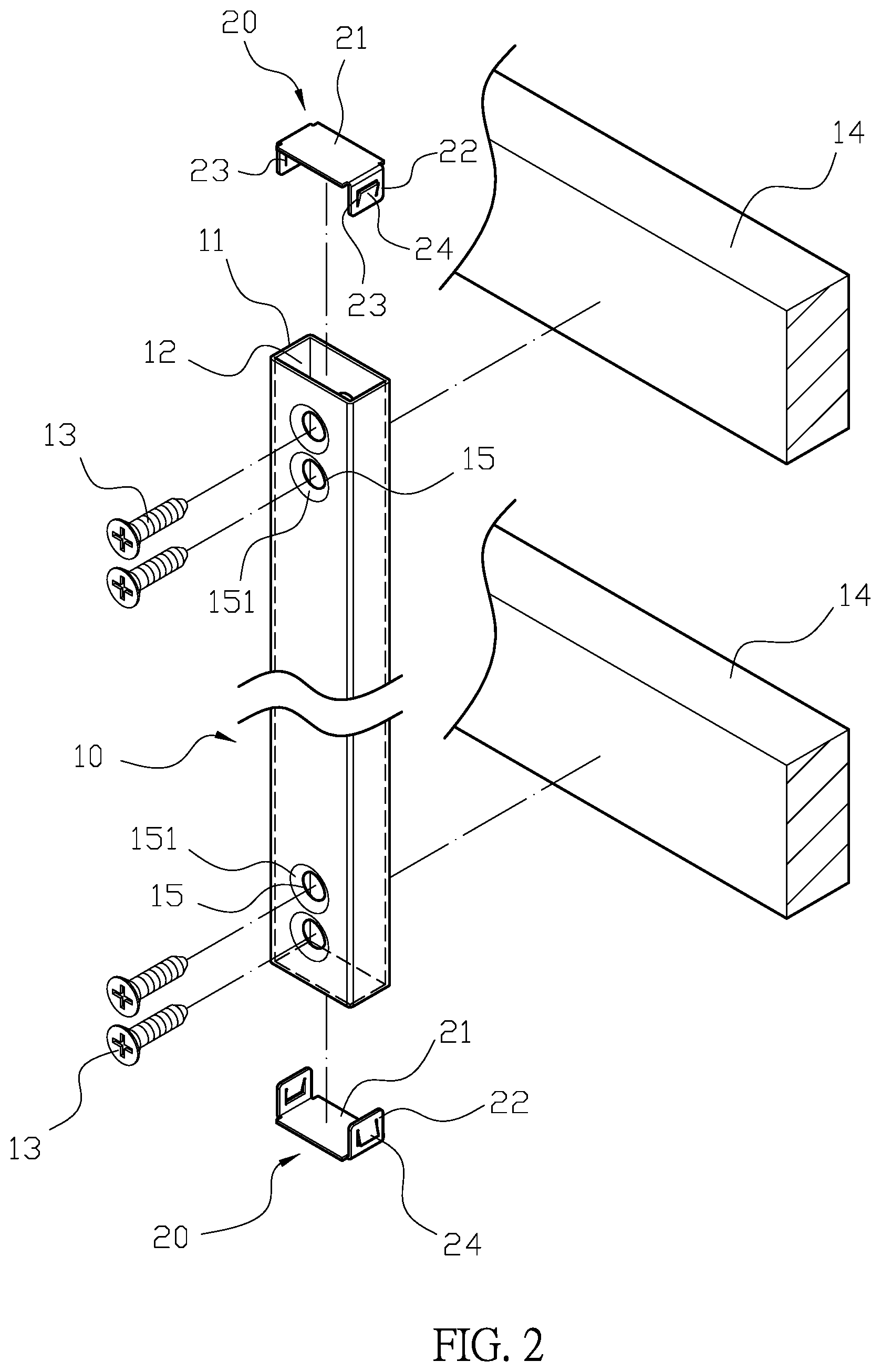
[0008] FIG. 2 is a perspective exploded view of the preferred embodiment according to the present invention.
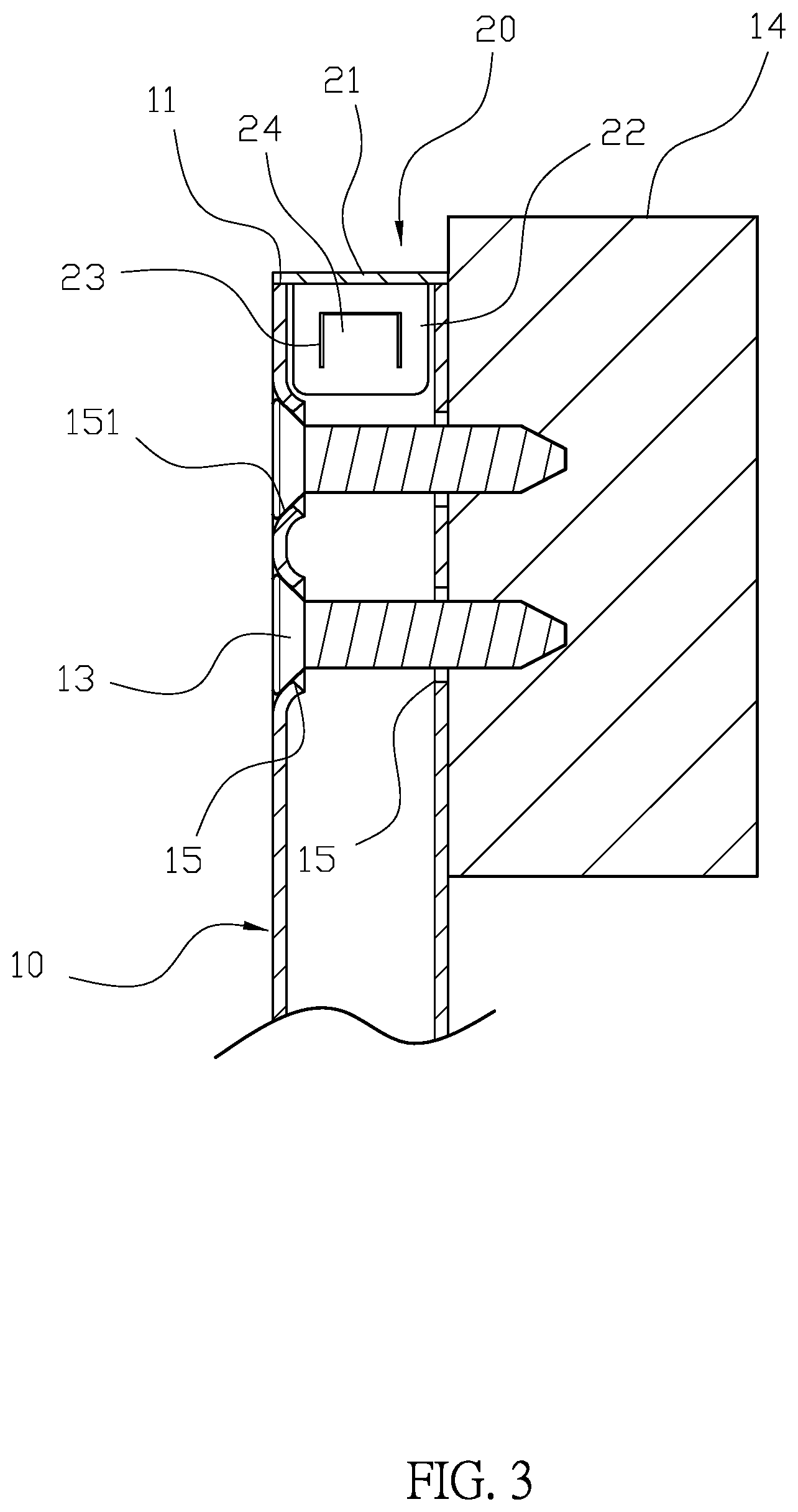
[0009] FIG. 3 is a cross-sectional view of preferred embodiment according to the present invention.
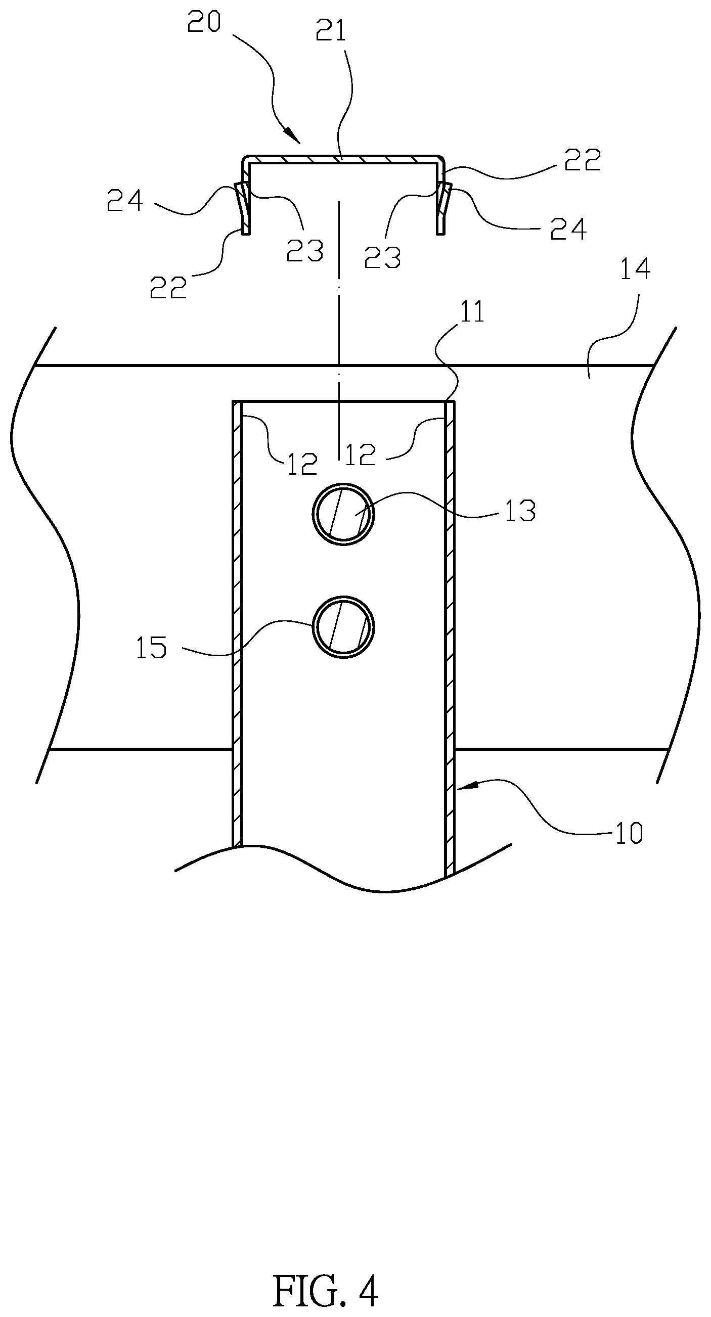
[0010] FIG. 4 is a schematic view showing the state of use of the preferred embodiment according to the present invention.
[0011] FIG. 5 is a cross-sectional view showing the state of use of the preferred embodiment according to the present invention.
[0012] FIG. 6 is a schematic drawing of the assembly block being embedded in the assembly face of the preferred embodiment according to the present invention.
DETAILED DESCRIPTION OF PREFERRED EMBODIMENT
[0013] First, please refer to FIGS. 1, 2, and 3. A railing structure comprises a railing tube 10 and at least one assembling block 20. The railing tube 10 is made from a material comprising aluminum, two openings 11 at each end have rectangular shapes. Two assembling faces 12 inside the railing pipe 10 are adjacent to the openings 11. The at least one assembling block 20 is made of a metallic material and has a hardness higher than a hardness of aluminum. The assembling block 20 comprising a plate 21 with two perpendicular side boards 22 symmetrically disposed along two sides. Each side board 22 further has a groove 23 partially covered by a positioning tongue 24, and a free end of the positioning tongue 24 faces toward the plate 21. Each side board 22 of the assembling block 20 is configured for being placed in a corresponding opening 11 of the railing tube 10, such that the plate 21 completely covers the opening 11 and the positioning tongue 24 engages with the assembling face 12. Thereby, the assembly block 20 cannot be separated from the railing pipe 10 easily, and the railing pipe 10 is provided with a plurality of screws 13 engaging with a plurality of rods 14. The railing pipe 10 is laterally provided with a plurality of the through apertures 15 penetrated by the screws 13, and the railing pipe 10 is provided with a tapered surface portion 151 on the periphery of the through aperture 15.
[0014] For actual use, please refer to FIGS. 1-7. The railing pipe 10 is a long tube made of aluminum material, and the two opening 11 of the railing pipe 10 are respectively provided with one assembling face 12. The assembling block 20 is made of a metal material having a hardness higher than that of the aluminum material, an alloy material such as steel or iron. The assembling block 20 is mounted on the opening 11 of the railing pipe 10, and the plate 21 of the assembling block 20 provides an effective shielding for the opening 11 with to prevent foreign matter from falling into the railing pipe 10 and cuts caused by the opening 11. The screws 13 are placed through the through apertures 15 of the railing pipes 10, so that a plurality of the railing pipes 10 can be arranged on the rod 14 at intervals. Furthermore, the side boards 22 of the assembling block 20 are placed in the opening 11 of the railing pipe 10, so that the positioning tongue 24 is subjected to be pressed by forward extrusion of the assembling face 12 of the railing pipe 10 to push the side boards 22 into the railing pipe 10. Also, the cover 21 presses against the opening 11 to provide cover. The positioning tongue 24 presses against the assembling face 12 entrenches under the assembling face 12 since material hardness of the assembly block 20 is greater than the material hardness of the railing pipe 10. Therefore, the rapid assembly of the railing pipe 10 and the assembling block 20 are achieved. When the external force is applied to pull on the assembly block 20, the positioning tongue 24 reaches under the assembling face 12 even deeper, so that the assembly block 20 cannot be separated from the railing pipe 10 in a non-destructive manner, which provides advantages of easy combination and improved combination strength.
[0015] Although the present invention has been explained in relation to its preferred embodiment, it is to be understood that many other possible modifications and variations can be made without departing from the spirit and scope of invention as hereinafter claimed.
* * * * *
D00000
D00001
D00002
D00003
D00004
D00005
D00006
XML
uspto.report is an independent third-party trademark research tool that is not affiliated, endorsed, or sponsored by the United States Patent and Trademark Office (USPTO) or any other governmental organization. The information provided by uspto.report is based on publicly available data at the time of writing and is intended for informational purposes only.
While we strive to provide accurate and up-to-date information, we do not guarantee the accuracy, completeness, reliability, or suitability of the information displayed on this site. The use of this site is at your own risk. Any reliance you place on such information is therefore strictly at your own risk.
All official trademark data, including owner information, should be verified by visiting the official USPTO website at www.uspto.gov. This site is not intended to replace professional legal advice and should not be used as a substitute for consulting with a legal professional who is knowledgeable about trademark law.