Machine And Method For The Production Of A Fibrous Web
Penteado; Caio ; et al.
U.S. patent application number 16/572819 was filed with the patent office on 2020-03-19 for machine and method for the production of a fibrous web. This patent application is currently assigned to Voith Patent GmbH. The applicant listed for this patent is Voith Patent GmbH. Invention is credited to Jonas Bergstrom, Caio Penteado.
| Application Number | 20200087857 16/572819 |
| Document ID | / |
| Family ID | 67220701 |
| Filed Date | 2020-03-19 |


| United States Patent Application | 20200087857 |
| Kind Code | A1 |
| Penteado; Caio ; et al. | March 19, 2020 |
MACHINE AND METHOD FOR THE PRODUCTION OF A FIBROUS WEB
Abstract
A machine for the production of a fibrous web, with a forming region, including a forming roll and a permeable inner belt which at least partially wraps around the forming roll together with an outer belt for formation of the fibrous web. A press device is immediately downstream from the forming region for additional dewatering of the fibrous web in a press nip and with a downstream drying cylinder. The fibrous web is carried supported on the inner belt from the forming region until the transfer to the heated surface of drying cylinder takes place. The inner belt is textured in order to provide texture to fibrous web and the transfer roll is a shoe roll in order to provide an extended transfer nip.
| Inventors: | Penteado; Caio; (Sao Paulo, BR) ; Bergstrom; Jonas; (Ulm, DE) | ||||||||||
| Applicant: |
|
||||||||||
|---|---|---|---|---|---|---|---|---|---|---|---|
| Assignee: | Voith Patent GmbH Heidenheim DE |
||||||||||
| Family ID: | 67220701 | ||||||||||
| Appl. No.: | 16/572819 | ||||||||||
| Filed: | September 17, 2019 |
| Current U.S. Class: | 1/1 |
| Current CPC Class: | D21F 3/10 20130101; D21F 11/006 20130101; D21F 3/08 20130101; D21F 11/14 20130101; D21F 7/008 20130101; D21H 27/002 20130101; D21F 9/02 20130101; D21F 3/0227 20130101; D21F 3/045 20130101; D21F 3/029 20130101; D21F 5/181 20130101 |
| International Class: | D21F 9/02 20060101 D21F009/02; D21F 3/04 20060101 D21F003/04; D21F 3/08 20060101 D21F003/08; D21F 3/02 20060101 D21F003/02; D21F 11/14 20060101 D21F011/14; D21F 11/00 20060101 D21F011/00; D21F 3/10 20060101 D21F003/10; D21F 7/00 20060101 D21F007/00; D21H 27/00 20060101 D21H027/00 |
Foreign Application Data
| Date | Code | Application Number |
|---|---|---|
| Sep 17, 2018 | DE | 102018122632.2 |
Claims
1. A machine for the production of a fibrous web, in particular a tissue web, with a forming region, the machine comprising: a forming roll; an outer belt; a permeable inner belt which at least partially wraps around said forming roll together with said outer belt for formation of the fibrous web in a forming region; and a press device immediately downstream from the forming region, the press device including: a press roll; a lower press belt; a transfer roll; a mating roll along with said press roll forming a press nip for additional dewatering of the fibrous web, wherein the press nip is the first press nip of said press device, wherein the fibrous web is carried through said press nip supported between said inner belt and said lower press belt; and a drying cylinder being downstream from said press device, wherein the fibrous web is carried supported on said inner belt in an extended transfer nip which is formed between said transfer roll and said drying cylinder from the forming region until the transfer from said inner belt to a heated surface of the drying cylinder, wherein said inner belt is textured providing texture to the fibrous web and said transfer roll is a shoe roll providing the extended transfer nip.
2. The machine of claim 1, wherein said lower press belt is a water absorbing press belt, in particular a press felt.
3. The machine of claim 1, wherein said press nip is a separate press nip.
4. The machine of claim 1, wherein said press roll is a shoe roll to form an extended press nip.
5. The machine of claim 1, wherein said press roll is arranged within a loop that is created by said inner belt and said mating roll is arranged within a loop that is created by said lower press belt, or that said press roll is arranged within the loop that is created by said lower press belt and that said mating roll is arranged within the loop that is created by said inner belt.
6. The machine of claim 1, wherein said mating roll is a suction roll.
7. The machine of claim 1, further comprising a steam blow box assigned to the fibrous web before said press nip when viewed in a machine direction, in order to impinge the fibrous web with steam.
8. The machine of claim 1, further comprising a suction device located within a loop that is created by said inner belt, said suction device being located prior to said press nip when viewed in machine direction.
9. The machine of claim 8, further comprising a blower hood assigned to said suction device for direct impingement of the fibrous web with steam and/or hot dry air and/or hot moist air.
10. The machine of claim 1, further comprising a suction guide roll which is partially wrapped by said inner belt, said suction guide roll being arranged within a loop created by said inner belt and between said press nip and said transfer roll.
11. The machine of claim 10, wherein said suction guide roll is partially wrapped in a wrap region by a permeable press belt in direct contact with the fibrous web.
12. The machine of claim 11, further comprising a hood positioned within a loop created by said press belt and in said wrap region for indirect impingement of the fibrous web with steam and/or hot dry air and/or hot moist air.
13. A method for the production of a fibrous web, in particular a tissue web, comprising the steps of: forming the fibrous web in a forming region, the forming region being where a forming roll and a permeable inner belt that at least partially wraps around said forming roll comes together with an outer belt; dewatering the fibrous web in a press device which is located immediately downstream from the forming region, the press device having a press nip which is formed by a press roll and a mating roll; supportedly carrying the fibrous web between said inner belt and a lower press belt through said press nip, wherein said press nip is a first press nip of the press device through which the fibrous web is routed; drying the fibrous web by a drying cylinder that is located downstream from the press device, wherein the fibrous web is delivered, in a transfer nip that is formed between a transfer roll and said drying cylinder, to a heated surface of said drying cylinder, the fibrous web being transported from the forming region to the transfer supported on said inner belt, said inner belt being textured, so that the fibrous web becomes textured and the fibrous web is carried supported between said inner belt and a lower press belt through said press nip.
14. The method of claim 13, wherein said lower press belt is a water absorbing press belt, in particular a press felt.
Description
BACKGROUND OF THE INVENTION
1. Field of the Invention
[0001] The invention relates to a machine for the production of a fibrous web.
2. Description of the Related Art
[0002] Document EP2796617 B1 discloses a Crescent former paper machine for the production of tissue paper. The tissue web is formed in a forming region between an outer wire and a felt and in a first configuration it is carried--supported on the felt together with an additional felt, through a shoe press and is subsequently transferred in a roll nip to the surface of the downstream drying cylinder. With this configuration, heavy tissue papers having a high specific volume can be produced energy efficiently. In a suggested second configuration, the tissue web is not routed through the shoe press nip but is transferred from the forming region directly onto the surface of the downstream drying cylinder. In addition, the arrangement of a suction felt guide roll for conditioning of the felt prior to the shoe press is proposed. A disadvantage of this arrangement is a limited increase in quality, in particular of the specific volume of the tissue web.
[0003] A similar Crescent former paper machine is disclosed in U.S. Pat. No. 6,547,924 B2. However, instead of the felt, an impermeable textured belt is provided in the former on which the tissue web is carried through a simply felted shoe press to the drying cylinder. The disadvantage of this machine exists in that there is insufficient dewatering in the shoe press. Only a low dry content can be achieved in the tissue web before the drying cylinder. This results in a high energy expenditure due to thermal drying of the web in the region of the drying cylinder. Moreover, the production speed and thus the output are thereby limited.
[0004] What is needed in the art is a machine and a method to improve the quality of the produced tissue web, in particular the specific volume, wherein good runability at high production speed, with efficient energy use and simple construction are considered.
SUMMARY OF THE INVENTION
[0005] The present invention produces a tissue web, with a forming region including a forming roll and a permeable inner belt which at least partially wraps around a forming roll together with an outer belt for the formation of the fibrous web, with a press device immediately downstream from the forming region. The press device includes a press nip which is formed by a press roll and a mating roll for additional dewatering of the fibrous web, wherein the press nip is the first nip of the press device. The fibrous web is carried through the press nip supported between the inner belt and a lower press belt. A drying cylinder is downstream from the press device, wherein the fibrous web is carried and supported on the inner belt--in a transfer nip which is formed between a transfer roll and the drying cylinder--from the forming region until the transfer to the heated surface of the drying cylinder.
[0006] An embodiment of the present invention includes a machine for the manufacture of a fibrous web, in particular a tissue web, having a forming region with a forming roll and a permeable inner belt, which at least partially wraps around the forming roll together with an outer belt for the formation of the fibrous web. There is a press device immediately downstream from the forming region that includes a press nip which is formed by a press roll and a mating roll for additional dewatering of the fibrous web. The press nip is the first nip of the press device, wherein the fibrous web--supported between the inner belt and a lower press belt--is carried through the press nip. There is a drying cylinder downstream from the press device, wherein the fibrous web is carried--from the forming region until the transfer in a transfer nip which is formed between a transfer roll and the drying cylinder--supported on the inner belt to the heated surface of the drying cylinder.
[0007] It is fundamental according to the present invention that the inner belt for providing texture to the fibrous web is textured and that the transfer roll is in the embodiment of a shoe roll in order to provide an extended transfer nip.
[0008] The machine of the present invention is characterized by a simple construction with which a fibrous web, in particular a tissue web having a high specific volume, and for which at the same time a high dry content can be achieved in the press device, can be produced reliably at a high speed. As a result of forming the fibrous web on the textured inner belt the web obtains a texture, which results in a high specific volume. This is maintained substantially even after running through the press nip, since the texture of the inner belt protects the texture of the fibrous web during the compression process. The compressibility of the inner belt is preferably less than that of the lower press belt.
[0009] The inner belt is permeable, in other words air and water permeable. This allows two-sided dewatering of the fibrous web in the press nip, wherein the extracted water is partially, in other words to a low extent, absorbed by the inner belt and the lower press belt. The lower press belt, which is in contact with the fibrous web, can be optimized in regard to quality, for example the specific volume of the produced fibrous web and a coordinated water absorption. This allows gentle dewatering without damaging or crushing the fibrous web. Thus, higher liner forces can be run in the press nip. Web travel without transfer between two clothings allows a reliable and stable operation of the machine, even at high output and speed. The transfer roll in the embodiment of a shoe roll is advantageous in the transfer of the fibrous web from the inner belt to the heated surface of the drying cylinder. Due to the texture of the inner belt that is impressed into the fibrous web, the web is only selectively compressed in the transfer nip, which is operated at only a low line force or low forming pressure. Thus, the increased dwell time of the fibrous web in the press nip has a positive effect on the transfer to the drying cylinder.
[0010] An additional advantage of the solution is the compact design in terms of the low space requirement in regard to the height of the machine. The length of the lower press belt can be kept short. The routing of the felt of the lower press belt can thus extend exclusively above the machine floor. This eliminates the requirement for a basement. Thus, this machine can also be installed in existing machine halls without basements, for the production of high-grade tissue webs with a high specific volume, for example for kitchen towels.
[0011] The inner textured belt can be a woven belt. It can also be in the embodiment of a permeable, at least on the fibrous web side, textured membrane or film.
[0012] The drying cylinder can be designed as a Yankee drying cylinder, in particular when producing fibrous tissue webs. The design of Yankee drying cylinders is known. They are characterized for example by large diameters in excess of 6 m and are steam heated.
[0013] For the production of certain tissue types with lower requirements in regard to the specific volume and higher demands in regard to production performance, this machine can be converted easily and cost effectively. For this purpose, the inner textured belt can be replaced by a conventional press felt and the press device can be deactivated. This means that the press device is either bypassed by the travel path of this press felt or that this press felt is routed through the opened press nip. This arrangement is thus consistent with a known Crescent former machine.
[0014] In one advantageous embodiment, the lower press belt is designed as a water absorbing press belt, in particular as a press felt. The press roll can be arranged within the loop that is created by the inner belt and the mating roll can be arranged within the loop that is created by the lower press belt. It is also conceivable to arrange the press roll within the loop that is created by the lower press belt and to arrange the mating roll within the loop that is created by the inner belt.
[0015] Moreover, the press nip can be designed as a separate press nip, in other words as a single press nip. This results in a simple design of the machine.
[0016] The press roll can be designed as a shoe roll to form an extended press nip. Thus, higher line forces can be run in the press nip. The extended press nip in this shoe press at the beginning of the press device, that is directly after the forming region allows gentle dewatering without damaging or crushing the fibrous web. At the same time, a higher dry content can be achieved in the fibrous web than is the case for example with a belt press.
[0017] In certain cases it is also possible to design the press roll as a solid surface roll.
[0018] The mating roll may be in the embodiment of a suction roll. As a result dewatering, in particular the direction of dewatering, can be influenced.
[0019] To increase the temperature and to improve the dewaterability of the fibrous web, a steam blow box can be assigned to the fibrous web before the press nip, in order to impinge the fibrous web with steam.
[0020] In one possible practical embodiment a suction device, located within the loop that is created by the inner belt, is arranged prior to the press nip when viewed in machine direction. This enables the texture of the fibrous web that was produced by the inner textured belt to be stabilized and maintained. The suction device is supplied with vacuum.
[0021] A blower hood may be allocated to the suction device for direct impingement of the fibrous web with steam and/or hot dry air and/or hot moist air.
[0022] In one conceivable further advancement a suction guide roll, which is partially wrapped by the inner belt, is arranged within the loop created by the inner belt and between the press nip and the transfer roll. The suction guide roll can be supplied with vacuum. Web travel can thereby be stabilized and the dry content for certain fibrous web grades can be increased prior to the drying cylinder. This arrangement is especially advantageous if the transfer roll is in the embodiment of a shoe press roll, according to the present invention. This ensures a reliable transfer of the fibrous web to the drying cylinder, even at a high dry content.
[0023] Moreover, the suction guide roll can be partially wrapped by a permeable press belt in direct contact with the fibrous web. The press belt can have an increased belt tension, for example, of higher than 20 kN/m, preferably higher than 30 kN/m. As a result the dry content of the fibrous web can be even further increased in certain fibrous web grades prior to transfer onto the drying cylinder.
[0024] In one additional possible embodiment a hood can be provided within the loop created by the press belt and in the region of the wrap for indirect impingement of the fibrous web with steam and/or hot dry air and/or hot moist air. Thus, the dry content of the fibrous web can be even further increased in certain fibrous web grades prior to the transfer to the drying cylinder.
[0025] The lower press belt is preferably designed as a water absorbing press belt, in particular as a press felt.
BRIEF DESCRIPTION OF THE DRAWINGS
[0026] The above-mentioned and other features and advantages of this invention, and the manner of attaining them, will become more apparent and the invention will be better understood by reference to the following description of embodiments of the invention taken in conjunction with the accompanying drawings, wherein:
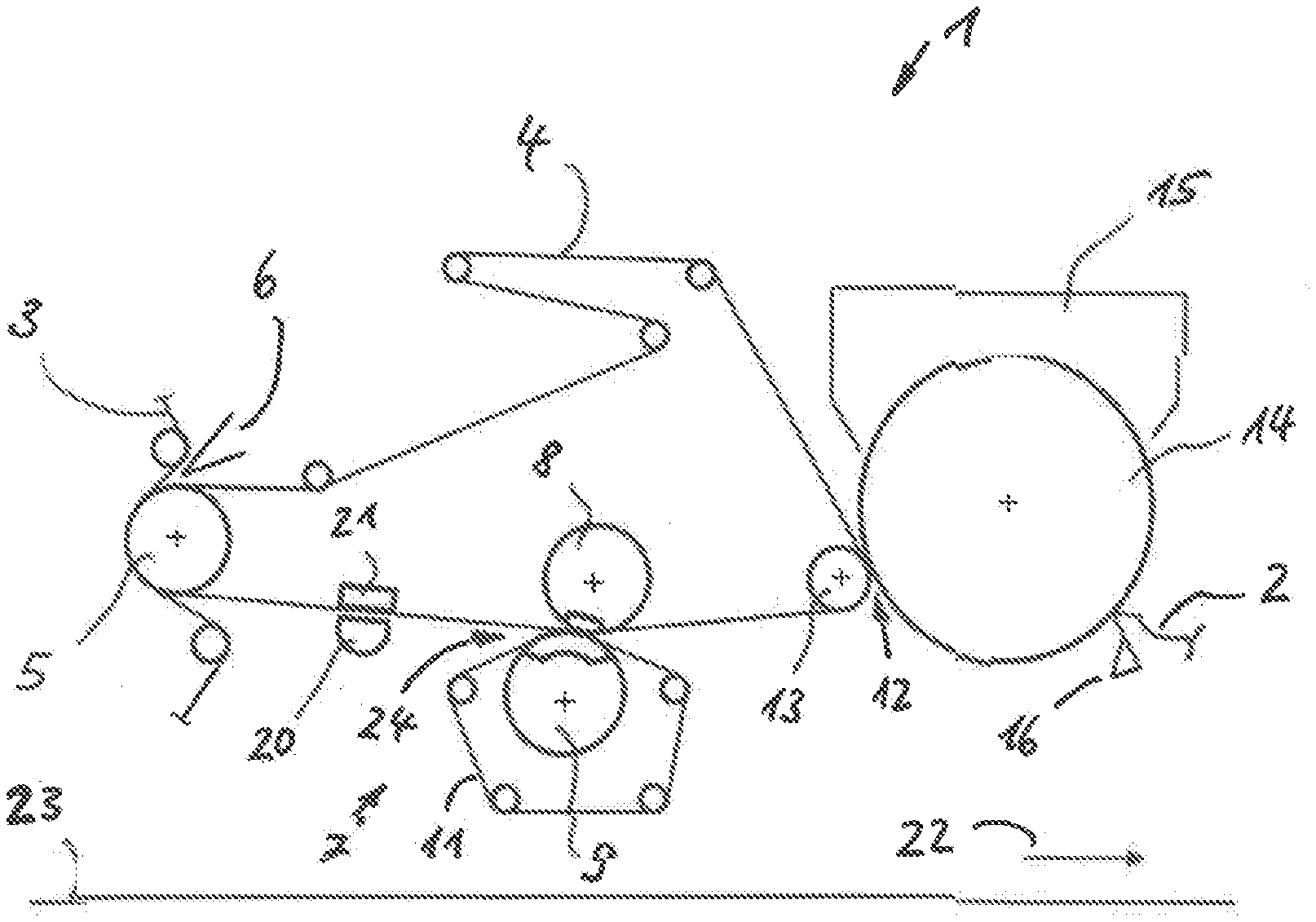
[0027] FIG. 1 illustrates a first embodiment of a machine according to the present invention in a simplified schematic representation;
[0028] FIG. 2 illustrates a second embodiment of a machine according to the present invention in a simplified schematic representation; and
[0029] FIG. 3 illustrates a third embodiment of a machine according to the present invention in another simplified schematic representation.
[0030] Corresponding reference characters indicate corresponding parts throughout the several views. The exemplifications set out herein illustrate embodiments of the invention and such exemplifications are not to be construed as limiting the scope of the invention in any manner.
DETAILED DESCRIPTION OF THE INVENTION
[0031] Referring now to the drawings, and particularly to FIG. 1 there is shown a first embodiment of an inventive machine 1 of the present invention in a simplified schematic representation. Machine 1 for the production of a fibrous web 2, in this example a tissue web, includes a forming region having a forming roll 5 and an inner belt 4 which, together with an outer belt 5, wraps at least partially around forming roll 5.
[0032] A headbox 6 feeds a fibrous stock suspension between belts 3, 4. This suspension is dewatered primarily in the common wrap-around region of belts 3, 4 in the region of forming roll 5, thus forming tissue web 2 and being transported on inner belt 4 onto and through a directly following press device 7. In this example, press device 7 includes a press roll 8 arranged at the top and a mating roll 9, arranged at the bottom, which together form a press nip 24 for further dewatering of tissue web 2. Mating roll 9 and press roll 8 can also be arranged conversely. Mating roll 8 is arranged as a suction roll with applied vacuum.
[0033] Press nip 24 of press device 7 is the first press nip 24 after the forming region. Upstream from press nip 24, viewed in a machine direction 22, a suction device 21, in this case a suction box 21 which is supplied with vacuum is located within the loop created by inner belt 4. A blower hood 20 is assigned to suction box 21 for direct impingement of fibrous web 2 with steam and/or hot dry air and/or hot moist air. In addition to tissue web 2 and inner belt 4, a lower press belt 11, which is in direct contact with tissue web 2, also runs through press nip 24. Lower press belt 11 is in the embodiment of a water absorbing press felt.
[0034] After additional dewatering of tissue web 2 in press device 7, tissue web 2, supported on inner belt 4 is led around a transfer roll 13 in the embodiment of a shoe roll. The latter, together with a drying cylinder 14, in this case a Yankee drying cylinder 14, creates a transfer nip 12 in which tissue web 2 is transferred from inner belt 4 onto the heated surface of Yankee drying cylinder 14 and continues to be thermally dried. Tissue web 2 is moreover supplied with hot air and/or overheated steam by way of a dryer hood 15 that is located in the region of Yankee drying cylinder 14. Tissue web 2 is subsequently creped on a doctor blade 16 and is removed from the surface of the Yankee drying cylinder and is transported directly or indirectly to a winding station, which is not illustrated herein.
[0035] Tissue web 2 is thus transported by one single belt 4 from the forming region to Yankee drying cylinder 14. According to the present invention, a transfer to an intermediate belt is not required for the production of qualitatively high-grade tissue webs with a high specific volume. This promotes good runability of the machine. The inner belt is permeable, in other words air and water permeable, and at least on the side that is in contact with tissue web 2 it is textured in order to provide texture to tissue web 2. Providing tissue web 2 with texture causes a high specific volume which is also referred to as bulk. In this example, the inner textured belt is a woven belt. It can also be in the embodiment of a permeable--at least on the fibrous web side--textured membrane or film.
[0036] The compressibility of inner textured belt 4 is less than that of the lower press belt 11. This protects the texture of tissue web 2 from being crushed when running through press nip 24. Machine 1 according to the present invention makes two-sided dewatering of fibrous web 2 in press nip 24 possible, wherein the extracted water is partially absorbed by inner belt 4 and primarily by lower press belt 11. Lower press belt 11, which is in contact with fibrous web 2, can be optimized in regard to quality, for example the specific volume of produced fibrous web 2 and in regard to the dewatering capacity. In order to form an extended transfer nip 12 together with Yankee drying cylinder 14, transfer roll 13 is designed as a shoe press roll.
[0037] Machine 1 is very compact in regard to its height. The length of lower press belt 11 is short. The travel path of the felt of lower press belt 11 is arranged exclusively above machine floor 23. This eliminates the requirement for a basement which is necessary in known machines for the production of tissue webs having high bulk. Thus, this machine can also be installed in existing machine halls without basements, for the production of high-grade tissue webs 2 with a high specific volume, for example for kitchen towels.
[0038] Now, additionally referring to FIG. 2 there is shown a second embodiment of inventive machine 1 in a simplified schematic representation. It differs from the embodiment shown in FIG. 1 in regard to a suction guide roll 17 which is arranged within the loop created by inner belt 4 and between press nip 24 and transfer roll 13 and which is partially wrapped by inner belt 4. Web travel can thereby be stabilized and the dry content for certain tissue web grades can be increased prior to drying cylinder 14. This arrangement is especially advantageous together with transfer roll 13 which, according to the invention is designed as a shoe press roll.
[0039] Now, additionally referring to FIG. 3 there is shown a third embodiment of inventive machine 1 in simplified schematic representation. It differs from the embodiment shown in FIG. 2 in that suction guide roll 17 is partially wrapped by a permeable press belt 18 and in that it is in direct contact with tissue web 2. The press belt applies pressure on tissue web 2 to increase the dry content. Press belt 18 has an increased belt tension of more than 20 kN/m, preferably more than 30 kN/m. The dry content of tissue web 2 can thus be increased in certain tissue web grades prior to the transfer to drying cylinder 14. A hood 19 is provided within the loop created by press belt 18 and in the region of the wrap for indirect impingement of the fibrous web with steam and/or hot dry air and/or hot moist air. Thus, the dry content of fibrous web 2 can be even further increased in certain tissue web grades prior to the transfer to the drying cylinder 14.
[0040] Corresponding elements shown in drawings of design examples are identified with the same reference numbers. The function of such elements in the individual drawings are consistent with one another if no deviances are described that would lead to contradictions. Repetitive descriptions are therefore dispensed with. It is also pointed out that differing characteristics of the illustrated design examples are interchangeable and can be combined with one another. The invention is therefore not restricted to the illustrated characteristics combination of the illustrated design examples.
[0041] While this invention has been described with respect to at least one embodiment, the present invention can be further modified within the spirit and scope of this disclosure. This application is therefore intended to cover any variations, uses, or adaptations of the invention using its general principles. Further, this application is intended to cover such departures from the present disclosure as come within known or customary practice in the art to which this invention pertains and which fall within the limits of the appended claims.
COMPONENT IDENTIFICATION LISTING
[0042] 1 Machine [0043] 2 Fibrous web [0044] 3 Outer belt [0045] 4 Inner belt [0046] 5 Forming roller [0047] 6 Headbox [0048] 7 Press device [0049] 8 Press roll [0050] 9 Mating roll [0051] 11 Lower press belt [0052] 12 Transfer nip [0053] 13 Transfer roll [0054] 14 Drying cylinder [0055] 15 Dryer hood [0056] 16 Doctor blade [0057] 17 Suction guide roll [0058] 18 Press belt [0059] 19 Hood [0060] 20 Blower hood [0061] 21 Suction device [0062] 22 Machine direction [0063] 23 Machine floor [0064] 24 Press nip
* * * * *
D00000
D00001
D00002
XML
uspto.report is an independent third-party trademark research tool that is not affiliated, endorsed, or sponsored by the United States Patent and Trademark Office (USPTO) or any other governmental organization. The information provided by uspto.report is based on publicly available data at the time of writing and is intended for informational purposes only.
While we strive to provide accurate and up-to-date information, we do not guarantee the accuracy, completeness, reliability, or suitability of the information displayed on this site. The use of this site is at your own risk. Any reliance you place on such information is therefore strictly at your own risk.
All official trademark data, including owner information, should be verified by visiting the official USPTO website at www.uspto.gov. This site is not intended to replace professional legal advice and should not be used as a substitute for consulting with a legal professional who is knowledgeable about trademark law.