Floating Caliper Brake Device For Railroad Vehicle
SAKAGUCHI; Kousuke ; et al.
U.S. patent application number 16/616016 was filed with the patent office on 2020-03-19 for floating caliper brake device for railroad vehicle. This patent application is currently assigned to NIPPON STEEL CORPORATION. The applicant listed for this patent is CENTRAL JAPAN RAILWAY COMPANY, NIPPON STEEL CORPORATION. Invention is credited to Jun ASANO, Kazuaki FUJITA, Seiji KANAMORI, Tomohiro OTSUKA, Kousuke SAKAGUCHI, Masanori SAWADA, Masashi SEKIYA, Hironori YOKOTA.
| Application Number | 20200086897 16/616016 |
| Document ID | / |
| Family ID | 64395687 |
| Filed Date | 2020-03-19 |


| United States Patent Application | 20200086897 |
| Kind Code | A1 |
| SAKAGUCHI; Kousuke ; et al. | March 19, 2020 |
FLOATING CALIPER BRAKE DEVICE FOR RAILROAD VEHICLE
Abstract
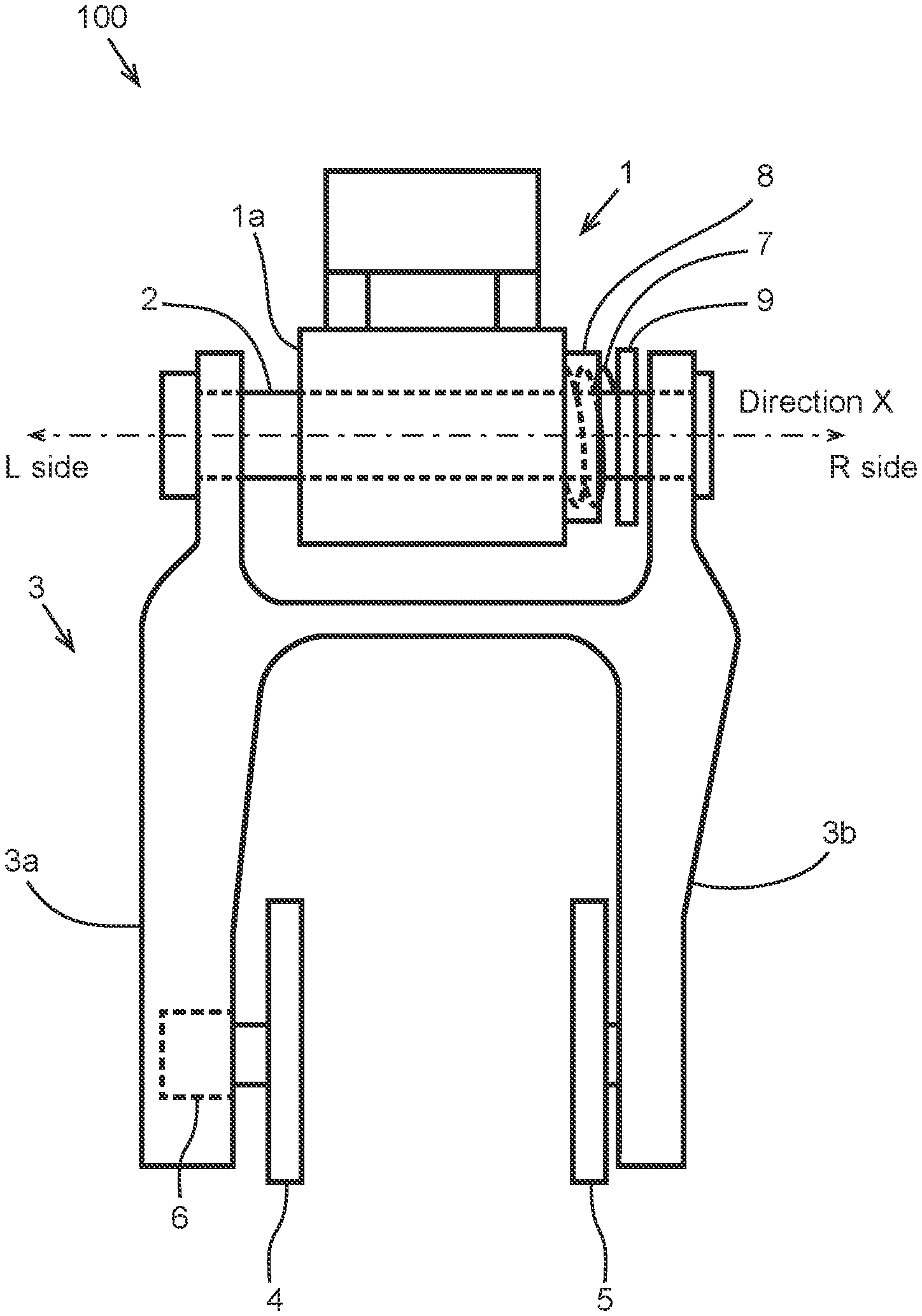
A floating caliper brake device for a railroad vehicle 100 includes: a support frame 1 that has a cylindrical portion 1a; a support pin 2 that is supported by the cylindrical portion 1a in such a manner as to be slidable in a direction X; a caliper 3 that includes a first arm portion 3a and a second arm portion 3b; a first brake shoe 4; a second brake shoe 5 that is opposite to the first brake shoe 4; a pressurizing device 6 that moves the first brake shoe 4 back and forth; an elastic member 7 that is expandable and contractible in the direction X; a stopper member 8 that is immovable relatively to the cylindrical portion 1a in the direction X; and a moving member 9 that is frictionally engaged with the support pin 2 in such a manner as to be slidable in the direction X, wherein end portions on an L side of the elastic member 7 and the stopper member 8 are each supported by the cylindrical portion 1a, at least a portion of an end portion on an R side of the stopper member 8 overlaps the moving member 9 when viewed in the direction X, and an end portion on the R side of the elastic member 7 projects toward the R side from the end portion on the R side of the stopper member 8 and is connected to the moving member 9.
| Inventors: | SAKAGUCHI; Kousuke; (Tokyo, JP) ; FUJITA; Kazuaki; (Tokyo, JP) ; SAWADA; Masanori; (Tokyo, JP) ; YOKOTA; Hironori; (Tokyo, JP) ; OTSUKA; Tomohiro; (Nagoya-shi, JP) ; ASANO; Jun; (Nagoya-shi, JP) ; SEKIYA; Masashi; (Nagoya-shi, JP) ; KANAMORI; Seiji; (Nagoya-shi, JP) | ||||||||||
| Applicant: |
|
||||||||||
|---|---|---|---|---|---|---|---|---|---|---|---|
| Assignee: | NIPPON STEEL CORPORATION Tokyo JP CENTRAL JAPAN RAILWAY COMPANY Nagoya-shi, Aichi JP |
||||||||||
| Family ID: | 64395687 | ||||||||||
| Appl. No.: | 16/616016 | ||||||||||
| Filed: | May 22, 2018 | ||||||||||
| PCT Filed: | May 22, 2018 | ||||||||||
| PCT NO: | PCT/JP2018/019723 | ||||||||||
| 371 Date: | November 22, 2019 |
| Current U.S. Class: | 1/1 |
| Current CPC Class: | F16D 2121/14 20130101; F16D 2121/08 20130101; F16D 2121/04 20130101; F16D 65/02 20130101; F16D 65/183 20130101; F16D 2127/02 20130101; F16D 55/2265 20130101; B61H 5/00 20130101 |
| International Class: | B61H 5/00 20060101 B61H005/00; F16D 55/2265 20060101 F16D055/2265 |
Foreign Application Data
| Date | Code | Application Number |
|---|---|---|
| May 23, 2017 | JP | 2017-101772 |
Claims
1. A floating caliper brake device for a railroad vehicle, comprising: a support frame that includes a cylindrical portion and is installed on a railroad bogie; a support pin that is supported by the cylindrical portion in such a manner as to be slidable in an axial direction of the cylindrical portion; a caliper that is fixed to the support pin, extends in a direction intersecting with the axial direction, and includes a first arm portion provided on a first side in the axial direction and a second arm portion provided on a second side in the axial direction; a first brake shoe that is provided on the first arm portion; a second brake shoe that is provided on the second arm portion and is opposite to the first brake shoe in the axial direction; a pressurizing device configured to move the first brake shoe back and forth with respect to the second brake shoe; an elastic member that is supported by the cylindrical portion and is expandable and contractible in the axial direction; a stopper member that is supported by the cylindrical portion in such a manner as to be immovable relatively to the cylindrical portion in the axial direction; and a moving member that is frictionally engaged with the support pin on the second side from the elastic member so as to be slidable in the axial direction, wherein an end portion of the elastic member on the first side and an end portion of the stopper member on the first side are each supported by the cylindrical portion, at least a portion of an end portion of the stopper member on the second side overlaps the moving member when viewed in the axial direction, and an end portion of the elastic member on the second side projects toward the second side from the end portion of the stopper member on the second side and is connected to the moving member.
2. The floating caliper brake device for a railroad vehicle according to claim 1, wherein the moving member is frictionally engaged with the support pin in such a manner that a maximum static friction occurring between the support pin and the moving member is greater than a restoring force of the elastic member.
3. The floating caliper brake device for a railroad vehicle according to claim 1, further comprising a restriction member configured to restrict a distance between the end portion on the first side of the elastic member and the end portion on the first side of the moving member to not more than a predetermined value.
4. The floating caliper brake device for a railroad vehicle according to claim 2, further comprising a restriction member configured to restrict a distance between the end portion on the first side of the elastic member and the end portion on the first side of the moving member to not more than a predetermined value.
Description
TECHNICAL FIELD
[0001] The present invention relates to a floating caliper brake device for a railroad vehicle.
BACKGROUND ART
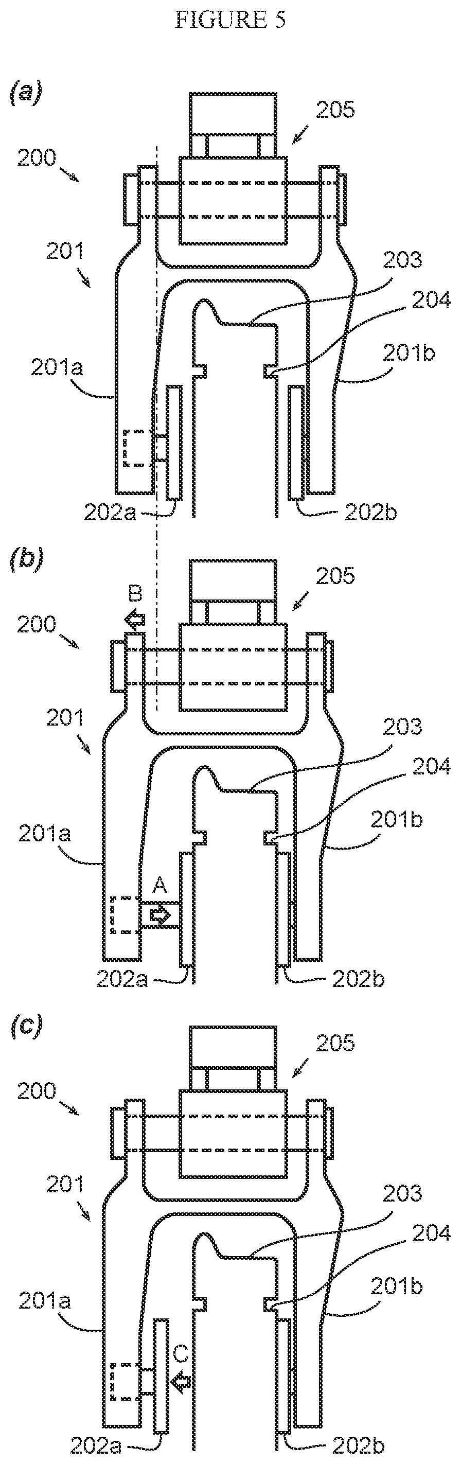
[0002] FIG. 5 is a schematic diagram illustrating a conventional floating caliper brake device 200. The floating caliper brake device 200 is a device that presses brake shoes 202a and 202b provided on paired arm parts 201a and 201b bifurcately formed at an end of a caliper 201, against a rotor 204 provided on a railroad wheel 203, so as to apply a brake on the rotating wheel 203.
[0003] The caliper 201 is supported in such a manner as to be movable with respect to a support frame 205 installed on a railroad bogie. Specifically, in braking, when the brake shoe 202a, which is one of the brake shoes, is moved in a direction A illustrated in FIG. 5(b) to be pressed against the rotor 204, a resultant reaction force causes the caliper 201 to move in a direction B, and the brake shoe 202b, which is the other one of the brake shoes, is pressed against the rotor 204.
[0004] However, even when the braking is released and the one brake shoe 202a is moved in a direction C to be separated from the rotor 204 as illustrated in FIG. 5(c), the other brake shoe 202b still remains in contact with rotor 204 to be dragged. This results in a problem in that only the other brake shoe 202b wears unnecessarily. Hence, there is a need for a mechanism that returns a position of the caliper 201 to a state illustrated in FIG. 5(a) after the braking is released.
[0005] For example, Patent Document 1 discloses a floating caliper brake device that is free from the dragging phenomenon. In addition, Patent Document 2 discloses a floating caliper brake device that stably makes a caliper retracting operation to reliably prevent a pad from being dragged.
LIST OF PRIOR ART DOCUMENTS
Patent Document
[0006] Patent Document 1: JP6-32773U
[0007] Patent Document 2: JP2016-89979A
SUMMARY OF INVENTION
Technical Problem
[0008] However, the caliper retracting mechanisms disclosed in Patent Documents 1 and 2 each utilize a restoring force of a rubber ring having an H-shape or U-shape cross section. Elastic force of a rubber ring changes in their use, which raises a problem in that it is difficult to adjust an amount of the restoration.
[0009] The present invention has an objective to provide a floating caliper brake device for a railroad vehicle for which the above problem is solved and in which gaps between brake shoes and a rotor are adjusted to prevent the brake shoes from being dragged.
Solution to Problem
[0010] The present invention is made to solve the problem described above, and the gist of the present invention is a floating caliper brake device for a railroad vehicle described below.
[0011] (1) A floating caliper brake device for a railroad vehicle, including
[0012] a support frame that includes a cylindrical portion and is installed on a railroad bogie;
[0013] a support pin that is supported by the cylindrical portion in such a manner as to be slidable in an axial direction of the cylindrical portion;
[0014] a caliper that is fixed to the support pin, extends in a direction intersecting with the axial direction, and includes a first arm portion provided on a first side in the axial direction and a second arm portion provided on a second side in the axial direction;
[0015] a first brake shoe that is provided on the first arm portion;
[0016] a second brake shoe that is provided on the second arm portion and is opposite to the first brake shoe in the axial direction;
[0017] a pressurizing device configured to move the first brake shoe back and forth with respect to the second brake shoe;
[0018] an elastic member that is supported by the cylindrical portion and is expandable and contractible in the axial direction;
[0019] a stopper member that is supported by the cylindrical portion in such a manner as to be immovable relatively to the cylindrical portion in the axial direction; and
[0020] a moving member that is frictionally engaged with the support pin on the second side from the elastic member so as to be slidable in the axial direction, wherein
[0021] an end portion of the elastic member on the first side and an end portion of the stopper member on the first side are each supported by the cylindrical portion,
[0022] at least a portion of an end portion of the stopper member on the second side overlaps the moving member when viewed in the axial direction, and
[0023] an end portion of the elastic member on the second side projects toward the second side from the end portion of the stopper member on the second side and is connected to the moving member.
[0024] (2) The floating caliper brake device for a railroad vehicle according to the above (1), wherein the moving member is frictionally engaged with the support pin in such a manner that a maximum static friction occurring between the support pin and the moving member is greater than a restoring force of the elastic member.
[0025] (3) The floating caliper brake device for a railroad vehicle according to the above (1) or (2), further including a restriction member configured to restrict a distance between the end portion on the first side of the elastic member and the end portion on the first side of the moving member to not more than a predetermined value.
Advantageous Effects of Invention
[0026] According to the present invention, an amount of restoration for the caliper is adjustable, and thus gaps between the brake shoes and a rotor can be adjusted, so that the brake shoes can be prevented from being dragged.
BRIEF DESCRIPTION OF DRAWINGS
[0027] FIG. 1 is a schematic diagram illustrating a configuration of a floating caliper brake device according to an embodiment of the present invention.
[0028] FIG. 2 is a schematic diagram illustrating the floating caliper brake device according to an embodiment of the present invention, where an elastic member, a stopper member, and a moving member, and their surroundings are enlarged.
[0029] FIG. 3 is a schematic diagram illustrating the floating caliper brake device according to another embodiment of the present invention, where an elastic member, a stopper member, and a moving member, and their surroundings are enlarged.
[0030] FIG. 4 is a schematic diagram illustrating the floating caliper brake device according to still another embodiment of the present invention, where an elastic member, a stopper member, and a moving member, and their surroundings are enlarged.
[0031] FIG. 5 is a schematic diagram illustrating a conventional floating caliper brake device.
DESCRIPTION OF EMBODIMENTS
[0032] Floating caliper brake devices for a railroad vehicle according to embodiments of the present invention will be described below with reference to the drawings.
[0033] FIG. 1 is a schematic diagram illustrating a configuration of a floating caliper brake device 100 for a railroad vehicle according to an embodiment of the present invention (hereinafter, referred to also as a "floating caliper brake device 100").
[0034] As illustrated in FIG. 1, the floating caliper brake device 100 includes a support frame 1, a support pin 2, a caliper 3, a first brake shoe 4, a second brake shoe 5, a pressurizing device 6, an elastic member 7, a stopper member 8, and a moving member 9.
[0035] The support frame 1 is a member that is installed on a railroad bogie and has a cylindrical portion 1a. The support pin 2 is supported in the cylindrical portion 1a in such a manner as to be slidable in an axial direction of the cylindrical portion 1a (hereinafter, referred to also as a "direction X"). The caliper 3 includes a first arm portion 3a and a second arm portion 3b. In the present embodiment, one of the arm portions that is provided on a first side (the L side in FIG. 1) is referred to as the first arm portion 3a, and the other of the arm portions that is provided on the second side (the R side in FIG. 1) is referred to as the second arm portion 3b. The first arm portion 3a and the second arm portion 3b both extend in a direction intersecting with the direction X.
[0036] The first brake shoe 4 and the second brake shoe 5 are provided on the first arm portion 3a and the second arm portion 3b, respectively, and face toward each other in the direction X. In a state where the floating caliper brake device 100 is installed on a railroad bogie, a rotor not illustrated is interposed between the first brake shoe 4 and the second brake shoe 5, and thus the first brake shoe 4 and the second brake shoe 5 face outside surfaces of the rotor.
[0037] The pressurizing device 6 is a device that moves the first brake shoe 4 back and forth with respect to the second brake shoe 5. There is no limitation to the mechanism for moving the first brake shoe 4 back and forth, and a hydraulic cylinder, a pneumatic cylinder, an electric motor, or the like can be used for the mechanism.
[0038] FIG. 2 is a schematic diagram illustrating the floating caliper brake device 100 according to an embodiment of the present invention, where the elastic member 7, the stopper member 8, and the moving member 9, and their surroundings are enlarged. The elastic member 7 is a member that is supported by the cylindrical portion 1a and expandable and contractible in the direction X. In the configuration illustrated in FIG. 2, a coiled spring is used as the elastic member 7.
[0039] The stopper member 8 is supported by the cylindrical portion 1a in such a manner to be immovable relatively to the cylindrical portion 1a in the direction X. More specifically, an end portion of the stopper member 8 on the L side is supported by the cylindrical portion 1a, and the stopper member 8 has a cross-sectional shape that extends toward the R side in such a manner as not to touch the elastic member 7. In addition, as illustrated in FIG. 2(a), in non-braking, an end portion of the elastic member 7 on the R side projects toward the R side from the end portion of the stopper member 8 on the R side.
[0040] The moving member 9 is frictionally engaged with the support pin 2 at a position on the R side from the elastic member 7 in such a manner as to be slidable in the direction X. Therefore, in the elastic member 7, its end portion on the L side is supported by the cylindrical portion 1a, and its end portion on the R side is connected to the moving member 9. In addition, the moving member 9 and at least a portion of the end portion of the stopper member 8 on the R side are positioned in such a manner as to overlap when viewed in the direction X.
[0041] How the elastic member 7, the stopper member 8, and the moving member 9 operate in braking will be described in more detail with reference to FIG. 2.
[0042] In an initial stage of non-braking, a positional relationship between the elastic member 7, the stopper member 8, and the moving member 9 is in a state illustrated in FIG. 2(a). The elastic member 7 is in a state where the elastic member 7 is contracted from its free length by a certain amount, and a restoring force caused by the contraction is less than a maximum static friction occurring between the cylindrical portion 1a and the support pin 2 and than a maximum static friction between the support pin 2 and the moving member 9. Therefore, each of the members is kept stationary.
[0043] In braking, as mentioned above, a reaction force caused by the first brake shoe 4 being pressed against the rotor causes the caliper 3 and the support pin 2 to move toward the L side, and thus the second brake shoe 5 is pressed against the rotor (see FIG. 5(b)). As a result, the moving member 9 moves together with the support pin 2 toward the L side by a predetermined amount with respect to the cylindrical portion 1a, which brings about a state illustrated in FIG. 2(b). At that time, an adjustment is made such that an amount of the movement of the support pin 2 in the braking becomes the same as an amount of the projection of the elastic member 7 from the stopper member 8 in the initial stage of non-braking, so that the movement of the support pin 2 stops at a position where the stopper member 8 comes into contact with the moving member 9, as illustrated in FIG. 2(b).
[0044] When the braking is released, a restoring force of the elastic member 7 applies a force toward the R side to the moving member 9, causing the support pin 2 to move together with the moving member 9 toward the R side. That is, the restoring force of the elastic member 7 in braking (the state illustrated in FIG. 2(b)) is greater than a maximum static friction occurring between the cylindrical portion 1a and the support pin 2 and less than a maximum static friction occurring between the support pin 2 and the moving member 9. When equilibrium is then reached between the restoring force of the elastic member 7 and a kinetic friction force occurring between the cylindrical portion 1a and the support pin 2, the movement of the support pin 2 and the moving member 9 toward the R side stops. By making an adjustment such that this state is set as an initial state (the state of FIG. 2(a)), operation of braking and releasing causes reiteration of the state of FIG. 2(a) and the state of FIG. 2(b).
[0045] With the above mechanism, the amount of the restoration can be kept constant, and thus the brake shoes can be prevented reliably from being dragged.
[0046] Here, the amount of the movement of the support pin 2 in the braking depends on distances between the two brake shoes and the rotor. With use, the brake shoes wear by friction with the rotor, and thus the distances between the brake shoes and the rotor gradually increase every time the abrasion occurs. As a result, a total amount of movement of the support pin 2 in the braking becomes long as compared with its initial state. That is, a position of the support pin 2 at a time of the braking moves toward the L side from the state of FIG. 2(b).
[0047] Although the moving member 9 is frictionally engaged with the support pin 2, an end portion of the moving member 9 on the L side abuts against the end portion of the stopper member 8 on the R side in the state of FIG. 2(b), and thus the moving member 9 cannot move together with the support pin 2 toward the L side. As a result, the moving member 9 is to slide toward the R side relatively to the support pin 2, which brings about the state illustrated in FIG. 2(c).
[0048] When the braking is thereafter released, the restoring force of the elastic member 7 applies the force toward the R side to the moving member 9, causing the support pin 2 to move together with the moving member 9 toward the R side. In a state where the equilibrium is then reached between the restoring force of the elastic member 7 and the kinetic friction force occurring between the cylindrical portion 1a and the support pin 2 (a state illustrated in FIG. 2(d)), the movement of the support pin 2 and the moving member 9 toward the R side stops. The moving member 9 is made slidable with respect to the support pin 2, which thus can keep the restoring force of the elastic member 7 unchanged in braking from the initial state and can keep the amount of the restoration constant after the braking is released.
[0049] FIG. 3 is a schematic diagram illustrating a floating caliper brake device 100 according to another embodiment of the present invention, where the elastic member 7, the stopper member 8, and the moving member 9, and their surroundings are enlarged. In the present embodiment, the floating caliper brake device 100 further includes a restriction member 10. The restriction member 10 is a member that restricts a distance between the end portion of the elastic member 7 on the L side and the end portion of the moving member 9 on the L side to not more than a predetermined value.
[0050] The inclusion of the restriction member 10 allows the members to be kept stationary even in a case where the restoring force of the elastic member 7 in the non-braking is greater than the maximum static friction occurring between the cylindrical portion 1a and the support pin 2. That is, a strong restoring force can be applied beforehand to the elastic member 7 as compared with a case of not including the restriction member 10. In addition, a stronger restoring force can be applied to the elastic member 7 in the braking. In addition, even in a case where a spring constant of the coiled spring used as the elastic member 7 somewhat changes with use, the amount of the restoration can be kept constant accurately.
[0051] FIG. 4 is a schematic diagram illustrating a floating caliper brake device 100 according to still another embodiment of the present invention, where the elastic member 7, the stopper member 8, and the moving member 9, and their surroundings are enlarged. As illustrated in FIG. 4, the moving member 9 may be made up of a plurality of members including a friction member 9a to be frictionally engaged with the support pin 2, a first butting member 9b to abut against the stopper member 8, and a second butting member 9c to abut against the restriction member 10.
[0052] Furthermore, although the elastic member 7 and the stopper member 8 are supported directly by the cylindrical portion 1a in the embodiments described above but may be supported by the cylindrical portion 1a via other members.
INDUSTRIAL APPLICABILITY
[0053] According to the present invention, an amount of restoration for the caliper is adjustable, and thus gaps between the brake shoes and a rotor can be adjusted, so that the brake shoes can be prevented from being dragged.
REFERENCE SIGNS LIST
[0054] 1. support frame [0055] 1a cylindrical portion
[0056] 2. support pin
[0057] 3. caliper [0058] 3a first arm portion [0059] 3b second arm portion
[0060] 4. first brake shoe
[0061] 5. second brake shoe
[0062] 6. pressurizing device
[0063] 7. elastic member
[0064] 8. stopper member
[0065] 9. moving member [0066] 9a friction member [0067] 9b first butting member [0068] 9c second butting member
[0069] 10. restriction member
[0070] 100. floating caliper brake device
[0071] 200. floating caliper brake device
[0072] 201. caliper [0073] 201a, 201b arm section [0074] 202a, 202b brake shoe
[0075] 203. wheel
[0076] 204. rotor
[0077] 205. support frame
* * * * *
D00000
D00001
D00002
D00003
D00004
D00005
XML
uspto.report is an independent third-party trademark research tool that is not affiliated, endorsed, or sponsored by the United States Patent and Trademark Office (USPTO) or any other governmental organization. The information provided by uspto.report is based on publicly available data at the time of writing and is intended for informational purposes only.
While we strive to provide accurate and up-to-date information, we do not guarantee the accuracy, completeness, reliability, or suitability of the information displayed on this site. The use of this site is at your own risk. Any reliance you place on such information is therefore strictly at your own risk.
All official trademark data, including owner information, should be verified by visiting the official USPTO website at www.uspto.gov. This site is not intended to replace professional legal advice and should not be used as a substitute for consulting with a legal professional who is knowledgeable about trademark law.