Food-Safe, Washable, Thermally-Conductive Robot Cover
Johnson; David M.S. ; et al.
U.S. patent application number 16/570855 was filed with the patent office on 2020-03-19 for food-safe, washable, thermally-conductive robot cover. The applicant listed for this patent is The Charles Stark Draper Laboratory, Inc.. Invention is credited to Cody Chu, David M.S. Johnson, Justin Rooney, Anthony Tayoun.
| Application Number | 20200086509 16/570855 |
| Document ID | / |
| Family ID | 68069913 |
| Filed Date | 2020-03-19 |

| United States Patent Application | 20200086509 |
| Kind Code | A1 |
| Johnson; David M.S. ; et al. | March 19, 2020 |
Food-Safe, Washable, Thermally-Conductive Robot Cover
Abstract
In an embodiment, a cover for an automated robot includes elastic sheets that are adhered to each other in a geometry. The geometry is configured to allow the elastic sheets to expand and contract while the automated robot moves within its range of motion. The elastic sheets are attached to the automated robot by elasticity of the elastic sheets. A first group of the elastic sheets forms an elastic collar configured to grip the automated robot at a distal end and a proximal end of the cover. A person of ordinary skill in the art can recognize that nonbreakably means that during operation of the robot, the elastic sheets hold their elasticity and integrity without breaking.
| Inventors: | Johnson; David M.S.; (Cambridge, MA) ; Rooney; Justin; (New York, NY) ; Chu; Cody; (Somerville, MA) ; Tayoun; Anthony; (Cambridge, MA) | ||||||||||
| Applicant: |
|
||||||||||
|---|---|---|---|---|---|---|---|---|---|---|---|
| Family ID: | 68069913 | ||||||||||
| Appl. No.: | 16/570855 | ||||||||||
| Filed: | September 13, 2019 |
Related U.S. Patent Documents
| Application Number | Filing Date | Patent Number | ||
|---|---|---|---|---|
| 62730703 | Sep 13, 2018 | |||
| 62730947 | Sep 13, 2018 | |||
| 62730933 | Sep 13, 2018 | |||
| 62730918 | Sep 13, 2018 | |||
| 62730934 | Sep 13, 2018 | |||
| 62731398 | Sep 14, 2018 | |||
| Current U.S. Class: | 1/1 |
| Current CPC Class: | B25J 9/1664 20130101; G05B 2219/49157 20130101; G05B 19/4061 20130101; G05D 1/02 20130101; H04L 67/12 20130101; B65G 1/137 20130101; G05B 2219/39342 20130101; G05B 2219/50391 20130101; B25J 9/1682 20130101; B25J 9/1674 20130101; G05B 2219/45111 20130101; B25J 13/085 20130101; G05B 2219/32335 20130101; B25J 15/0052 20130101; B25J 15/0408 20130101; G05B 2219/39001 20130101; G05B 2219/40201 20130101; B25J 19/023 20130101; B25J 19/0083 20130101; G05B 2219/40411 20130101; G05B 2219/40497 20130101; G06N 3/08 20130101; B25J 9/1676 20130101; B25J 11/0045 20130101; B25J 9/1633 20130101; G10L 15/22 20130101; G06K 9/00355 20130101; B25J 13/088 20130101; G05B 2219/39091 20130101; G05B 2219/39319 20130101; G06Q 10/06316 20130101; B25J 9/1653 20130101; B25J 9/1666 20130101; B25J 9/1697 20130101; B25J 9/0009 20130101; A47J 44/00 20130101; B25J 9/161 20130101; G05B 2219/40202 20130101; B23Q 3/15503 20161101; B25J 13/003 20130101; G05B 2219/39468 20130101 |
| International Class: | B25J 19/00 20060101 B25J019/00; B25J 11/00 20060101 B25J011/00 |
Claims
1. A cover for an automated robot, the cover comprising: a plurality of elastic sheets that are adhered to each other in a geometry, the geometry configured to allow the plurality of elastic sheets to expand and contract while the automated robot moves within its range of motion; wherein the plurality of elastic sheets is attached to the automated robot by elasticity of the elastic sheets; wherein a first group of the elastic sheets forms an elastic collar configured to grip the automated robot at a distal end and a proximal end of the cover.
2. The cover of claim 1, wherein the geometry is configured to durably stretch and durably contract the plurality of elastic sheets for the range of motion of the robot.
3. The cover of claim 1, further comprising: malleable media, placed between the robot and the plurality of elastic sheets, such that the malleable media expands the cover from a surface of the robot and lessens constriction of elastic material onto the surface of the robot.
4. The cover of claim 1, wherein the elastic sheets are inflated to expand the cover from a surface of the robot to lessen constriction of the elastic sheets onto the robot surface.
5. The cover of claim 1, wherein the automated robot has up to seven degrees of freedom.
6. The cover of claim 1, wherein the geometry is configured with an entry point and an exit point, the geometry further configured to allow air to flow from the entry point to the exit point.
7. The cover of claim 6, wherein the entry point or exit point can further be configured to allow cables or hoses to enter the cover.
8. The cover of claim 1, further comprising: internal support rings configured to prevent the cover from directly contacting the robot to reduce friction with the robot; wherein at least one of the internal support rings including at least one hole that permits air, fluid, cables or hoses to be passed through them.
9. The cover of claim 1, further comprising: at least one external support ring that is configured to support an external cable or hose attached to the automated robot.
10. The cover of claim 9, wherein the at least one external support ring is at least one of a strap, hose clamp, and elastic strap.
11. The cover of claim 1, wherein a second group of the elastic sheets forms a second elastic collar configured to grip the automated robot at a second opening of the cover.
12. The cover of claim 1, wherein at least one of the distal end and the proximal end have a hole.
13. The cover of claim 1, wherein the distal end and proximal end are closed.
14. The cover of claim 1, further comprising at least one internal support ring including an inner ring fixed to the robot and an outer ring which is connected to the inner ring by a low friction interface consisting of a ball bearing, roller bearing, or a sleeve bearing.
15. A method for covering an automated robot, the method comprising: adhering a plurality of elastic sheets to each other in a geometry, the geometry configured to allow the plurality of elastic sheets to expand and contract while the automated robot moves within its range of motion; wherein the plurality of elastic sheets is attached to the automated robot by elasticity of the elastic sheets; wherein a first group of the elastic sheets forms an elastic collar configured to grip the automated robot at a distal end and a proximal end of the cover.
16. The method of claim 15, wherein the geometry is configured based on the range of motion of the robot, the geometry configured to durably stretch and durably contract the plurality of non-porous elastic sheets for the range of motion of the robot.
17. The method of claim 15, further comprising: placing malleable media between the robot and the plurality of non-porous elastic sheets, such that the malleable media expands the cover from a surface of the robot and lessens constriction of elastic material onto the surface of the robot.
18. The method of claim 15, wherein the elastic sheets are inflated to expand the cover from a surface of the robot to lessen constriction of the elastic sheets onto the robot surface.
19. The method of claim 15, wherein the automated robot has up to seven degrees of freedom.
20. The method of claim 15, wherein the geometry is configured with an air intake hole to allow air to flow from a first end of the cover to a second end.
Description
RELATED APPLICATIONS
[0001] This application claims the benefit of U.S. Provisional Application No. 62/730,703, filed on Sep. 13, 2018, U.S. Provisional Application No. 62/730,947, filed on Sep. 13, 2018, U.S. Provisional Application No. 62/730,933, filed on Sep. 13, 2018, U.S. Provisional Application No. 62/730,918, filed on Sep. 13, 2018, U.S. Provisional Application No. 62/730,934, filed on Sep. 13, 2018 and U.S. Provisional Application No. 62/731,398, filed on Sep. 14, 2018.
[0002] This application is related to U.S. Patent Application titled "Manipulating Fracturable And Deformable Materials Using Articulated Manipulators", Attorney Docket No. 5000.1049-001; U.S. Patent Application titled "Food-Safe, Washable Interface For Exchanging Tools", Attorney Docket No. 5000.1051-000; U.S. Patent Application titled "An Adaptor for Food-Safe, Bin-Compatible, Washable, Tool-Changer Utensils", Attorney Docket No. 5000.1052-001; U.S. Patent Application titled "Locating And Attaching Interchangeable Tools In-Situ", Attorney Docket No. 5000.1053-001; U.S. Patent Application titled "Determining How To Assemble A Meal", Attorney Docket No. 5000.1054-001; U.S. Patent Application titled "Controlling Robot Torque And Velocity Based On Context", Attorney Docket No. 5000.1055-001; U.S. Patent Application titled "Stopping Robot Motion Based On Sound Cues", Attorney Docket No. 5000.1056-000; U.S. Patent Application titled "Robot Interaction With Human Co-Workers", Attorney Docket No. 5000.1057-001; U.S. Patent Application titled "Voice Modification To Robot Motion Plans", Attorney Docket No. 5000.1058-000; and U.S. Patent Application titled "One-Click Robot Order", Attorney Docket No. 5000.1059-000, all of the above U.S. Patent Applications having a first named inventor David M. S. Johnson and all being filed on the same day, Sep. 13, 2019.
[0003] The entire teachings of the above applications are incorporated herein by reference.
BACKGROUND
[0004] Traditionally, the food industry employs human labor to manipulate ingredients with the purpose of either assembling a meal such as a salad or a bowl, or packing a box of ingredients such as those used in grocery shopping, or preparing the raw ingredients. Robots have not yet been able to assemble complete meals from prepared ingredients in a food-service setting such as a restaurant, largely because the ingredients are arranged unpredictably and change shape in difficult-to-predict ways rendering traditional methods to move material ineffective without extensive modifications to existing kitchens. Additionally, traditional material handling methods are ill-suited to moving cooked foods without altering their texture and taste-profile. These difficulties arise because the friction, stiction, and viscosity of commonly consumed foods cause auger, conveyor, and suction mechanisms to become clogged and soiled, while these mechanisms simultaneously impart forces on the foodstuffs which alter their texture, consistency, and taste-profile in unappetizing ways.
SUMMARY
[0005] In an embodiment, a non-porous elastic pull-over cover for an automatic robot can prevent moisture accumulation and material ingress. The cover may include cut sheets adhered or molded together to form an optimized geometry for robot articulation. Joints in the cover are smooth or non-existent to aid cleanability and washability in soiled conditions. The cover can be constrained at the tip and end of the cover with additional elastic material to be correctly positioned on the robot. Pressurized air may pass through the inside of cover to aid robot mobility and robot thermal regulation.
[0006] In an embodiment, a cover for an automated robot includes elastic sheets that are adhered to each other in a geometry. The geometry is configured to allow the elastic sheets to expand and contract while the automated robot moves within its range of motion. The elastic sheets are attached to the automated robot by elasticity of the elastic sheets. A first group of the elastic sheets forms an elastic collar configured to grip the automated robot at a distal end and a proximal end of the cover. A person of ordinary skill in the art can recognize that durable and durably means that during operation of the robot, the elastic sheets hold their elasticity and integrity without breaking.
[0007] In an embodiment, the elastic sheets are non-porous.
[0008] In an embodiment, the geometry is configured to durably stretch and durably contract the plurality of non-porous elastic sheets for the range of motion of the robot.
[0009] In an embodiment, the cover includes malleable media, placed between the robot and the elastic sheets, such that the malleable media expands the cover from a surface of robot and lessens constriction of elastic material onto the surface of the robot.
[0010] In an embodiment, the elastic sheets are inflated to expand the cover from a surface of the robot to lessen constriction of the elastic sheets onto the robot surface.
[0011] In an embodiment, the automated robot has up to seven degrees of freedom.
[0012] In an embodiment, the geometry is configured with an entry point and an exit point and to allow air to flow from the entry point to the exit point. The entry point or exit point can further be configured to allow cables or hoses to enter the cover.
[0013] In an embodiment, the cover further includes internal support rings that are configured to prevent the cover from directly contacting the robot to reduce friction with the robot. The internal support rings including at least one hole that permits air, fluid, cables or hoses to be passed through them. The support rings may provide external mounting points to fix an external cable or hose. The external mounting points may protrude through the cover, and a water-tight seal is formed by the elastic of the cover around the opening. The external mounting points may be attached via magnets.
[0014] In an embodiment, the internal support rings may include an internal ring which is fixed to the robot and rotates with the robot, and an external concentric ring which is able to rotate with respect to the internal ring by way of a ball bearing, sleeve bearing, or other low friction mechanism. The pass-through holes which carry cables maybe located in either the inner portion of the ring which rotates with the robot or the outer portion of the ring which stays nearly fixed to the elastic sheet. The friction between the elastic sheet and the outer ring causes it to rotate with respect to the inner ring as the robot joints move.
[0015] The cover may further include at least one external support ring that is configured to support an external cable or hose attached to the automated robot. The at least one external support ring can be at least one of a strap, hose clamp, and elastic strap.
[0016] In an embodiment, a second group of the non-porous elastic sheets forms a second elastic collar configured to grip the automated robot at a second opening of the cover.
[0017] In an embodiment, at least one of the distal end and the proximal end have a hole.
[0018] In an embodiment, the distal end and proximal end are closed.
[0019] In an embodiment, the cover further includes at least one internal support ring including an inner ring fixed to the robot and an outer ring which is connected to the inner ring by a low friction interface consisting of a ball bearing, roller bearing, or a sleeve.
[0020] In an embodiment, a method for covering an automated robot includes adhering a plurality of elastic sheets to each other in a geometry. The geometry configured to allow the plurality of elastic sheets to durably expand and contract while the automated robot performs its range of motion. The plurality of elastic sheets is attached to the automated robot by elasticity of the elastic sheets and free of any fastener. A first group of the elastic sheets forms an elastic collar configured to grip the automated robot at an opening of the cover.
BRIEF DESCRIPTION OF THE DRAWINGS
[0021] The foregoing will be apparent from the following more particular description of example embodiments, as illustrated in the accompanying drawings in which like reference characters refer to the same parts throughout the different views. The drawings are not necessarily to scale, emphasis instead being placed upon illustrating embodiments.
[0022] FIG. 1 is a block diagram illustrating an example embodiment of a quick service food environment of embodiments of the present invention.
[0023] FIG. 2 is a diagram of an example embodiment of a cover on a robotic arm.
[0024] FIG. 3 is a diagram of an internal support ring.
[0025] FIG. 4 is a diagram of an internal support ring with a sleeve bearing.
DETAILED DESCRIPTION
[0026] A description of example embodiments follows.
[0027] Robots are used to manipulate tools and objects in environments with hazards that could damage the robot. For example, locations with excessive dust, moisture and vermin could harm the robot. Crevices in a traditional robot also serve as points of rot and contamination in food environments. To prevent the buildup of soil and the potential for bacteria and vermin to reside in or on the robot, surfaces should be smooth and non-porous to aid cleanability. Traditional robot covers are woven or inelastic, limiting the robot's range of movement. Over time, the porous surfaces also tend to be contaminated with food particles that lead to rot, vermin, and soiling.
[0028] Operating a robot in a food preparation environment, such as a quick service restaurant, can be challenging for several reasons. First, the end effectors (e.g., utensils), that the robot uses need to remain clean from contamination. Contamination can include allergens (e.g., peanuts), dietary preferences (e.g., contamination from pork for a vegetarian or kosher customer), dirt/bacteria/viruses, or other non-ingestible materials (e.g., oil, plastic, or particles from the robot itself). Second, the robot should be operated within its design specifications, and not exposed to excessive temperatures or incompatible liquids, without sacrificing cleanliness. Third, the robot should be able to manipulate food stuffs, which are often fracturable and deformable materials, and further the robot must be able to measure an amount of material controlled by its utensil in order to dispense specific portions. Fourth, the robot should be able to automatically and seamlessly switch utensils (e.g., switch between a ladle and salad tongs). Fifth, the utensils should be adapted to be left in an assigned food container and interchanged with the robot as needed, in situ. Sixth, the interchangeable parts (e.g., utensils) should be washable and dishwasher safe. Seventh, the robot should be able to autonomously generate a task plan and motion plan(s) to assemble all ingredients in a recipe, and execute that plan. Eighth, the robot should be able to modify or stop a motion plan based on detected interference or voice commands to stop or modify the robot's plan. Ninth, the robot should be able to minimize the applied torque based on safety requirements or the task context or the task parameters (e.g., density and viscosity) of the material to be gathered. Tenth, the system should be able to receive an electronic order from a user, assemble the meal for the user, and place the meal for the user in a designated area for pickup automatically with minimal human involvement.
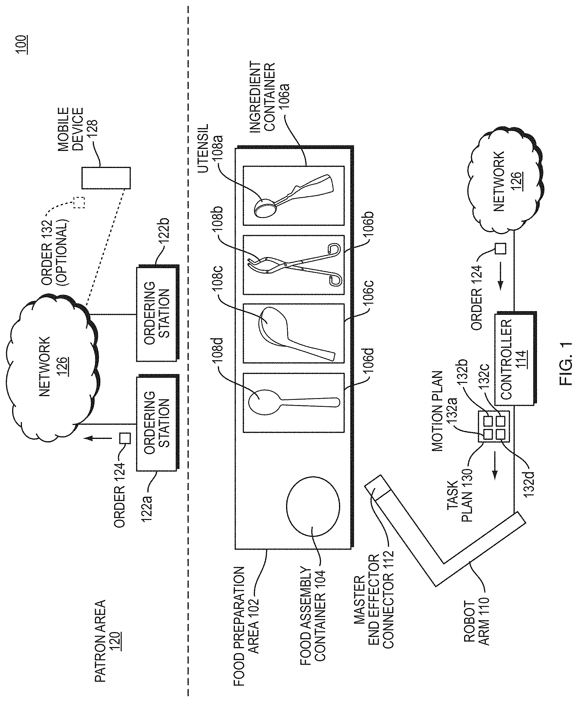
[0029] FIG. 1 is a block diagram illustrating an example embodiment of a quick service food environment 100 of embodiments of the present disclosure. The quick service food environment 100 includes a food preparation area 102 and a patron area 120.
[0030] The food preparation area 102 includes a plurality of ingredient containers 106a-d each having a particular foodstuff (e.g., lettuce, chicken, cheese, tortilla chips, guacamole, beans, rice, various sauces or dressings, etc.). Each ingredient container 106a-d stores in situ its corresponding ingredients. Utensils 108a-d may be stored in situ in the ingredient containers or in a stand-alone tool rack 109. The utensils 108a-d can be spoons, ladles, tongs, dishers (scoopers), spatulas, or other utensils. Each utensil 108a-e is configured to mate with and disconnect from a tool changer interface 112 of a robot arm 110. While the term utensil is used throughout this application, a person having ordinary skill in the art can recognize that the principles described in relation to utensils can apply in general to end effectors in other contexts (e.g., end effectors for moving fracturable or deformable materials in construction with an excavator or backhoe, etc.); and a robot arm can be replaced with any computer controlled actuatable system which can interact with its environment to manipulate a deformable material. The robot arm 110 includes sensor elements/modules such as stereo vision systems (SVS), 3D vision sensors (e.g., Microsoft Kinect.TM. or an Intel RealSense.TM.), LIDAR sensors, audio sensors (e.g., microphones), inertial sensors (e.g., internal motion unit (IMU), torque sensor, weight sensor, etc.) for sensing aspects of the environment, including pose (i.e., X, Y, Z coordinates and roll, pitch, and yaw angles) of tools for the robot to mate, shape and volume of foodstuffs in ingredient containers, shape and volume of foodstuffs deposited into food assembly container, moving or static obstacles in the environment, etc.
[0031] To initiate an order, a patron in the patron area 120 enters an order 124 in an ordering station 122a-b, which is forwarded to a network 126. Alternatively, a patron on a mobile device 128 can, within or outside of the patron area 120, generate an optional order 132. Regardless of the source of the order, the network 126 forwards the order to a controller 114 of the robot arm 110. The controller generates a task plan 130 for the robot arm 110 to execute.
[0032] The task plan 130 includes a list of motion plans 132a-d for the robot arm 110 to execute. Each motion plan 132a-d is a plan for the robot arm 110 to engage with a respective utensil 108a-e, gather ingredients from the respective ingredient container 106a-d, and empty the utensil 108a-e in an appropriate location of a food assembly container 104 for the patron, which can be a plate, bowl, or other container. The robot arm 110 then returns the utensil 108a-e to its respective ingredient container 106a-d, the tool rack 109, or other location as determined by the task plan 130 or motion plan 132a-d, and releases the utensil 108a-d. The robot arm executes each motion plan 132a-d in a specified order, causing the food to be assembled within the food assembly container 104 in a planned and aesthetic manner.
[0033] Within the above environment, various of the above described problems can be solved. The environment 100 illustrated by FIG. 1 can improve food service to patrons by assembling meals faster, more accurately, and more sanitarily than a human can assemble a meal. Some of the problems described above can be solved in accordance with the disclosure below.
[0034] The present disclosure relates to a non-porous elastic cover for robots, and particularly to covers for robots in food service, production, and assembly.
[0035] Robots can manipulate tools and objects in environments with hazards that could damage the robot. For example, excessive dust, moisture, or vermin can harm a robot during its operation, or even during idle time. Crevices in a traditional robot can become points of rot and contamination, which is especially important in food environments. To prevent the buildup of particles such as dirt, soil, moisture, and creating a breeding ground for bacteria, viruses, and vermin to reside in or on the robot, surfaces should be smooth and non-porous to aid cleanability. It can be difficult to provide such a surface with robot machinery itself without sacrificing performance. Therefore, a robot cover is needed to provide protection to the robot.
[0036] Traditional robot covers are woven or inelastic. Such traditional robot covers limit the range of movement of the robot. Over time, the porous surfaces of these covers also tend to be contaminated with food particles that lead to rot, vermin, and soiling.
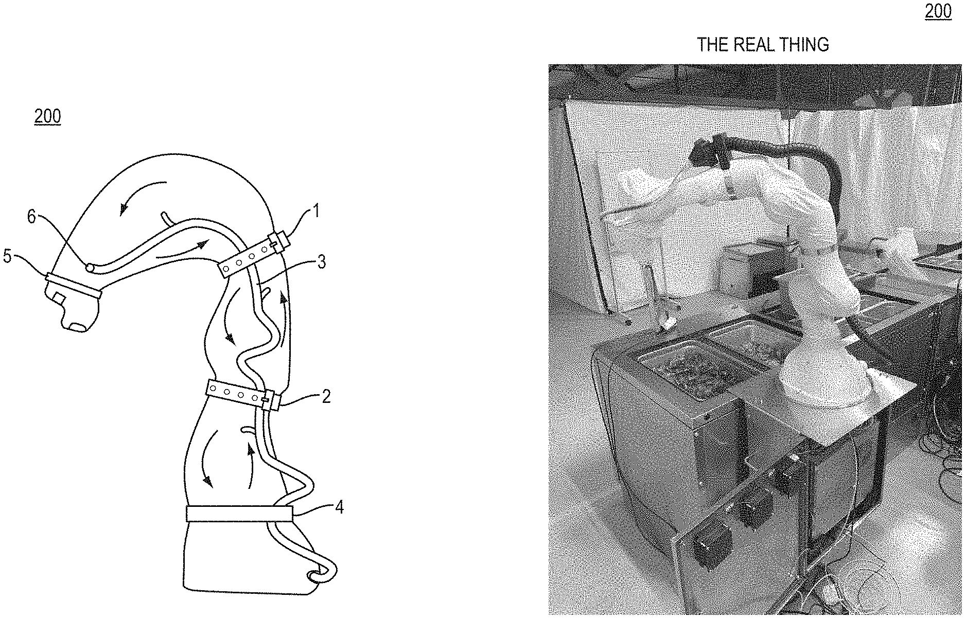
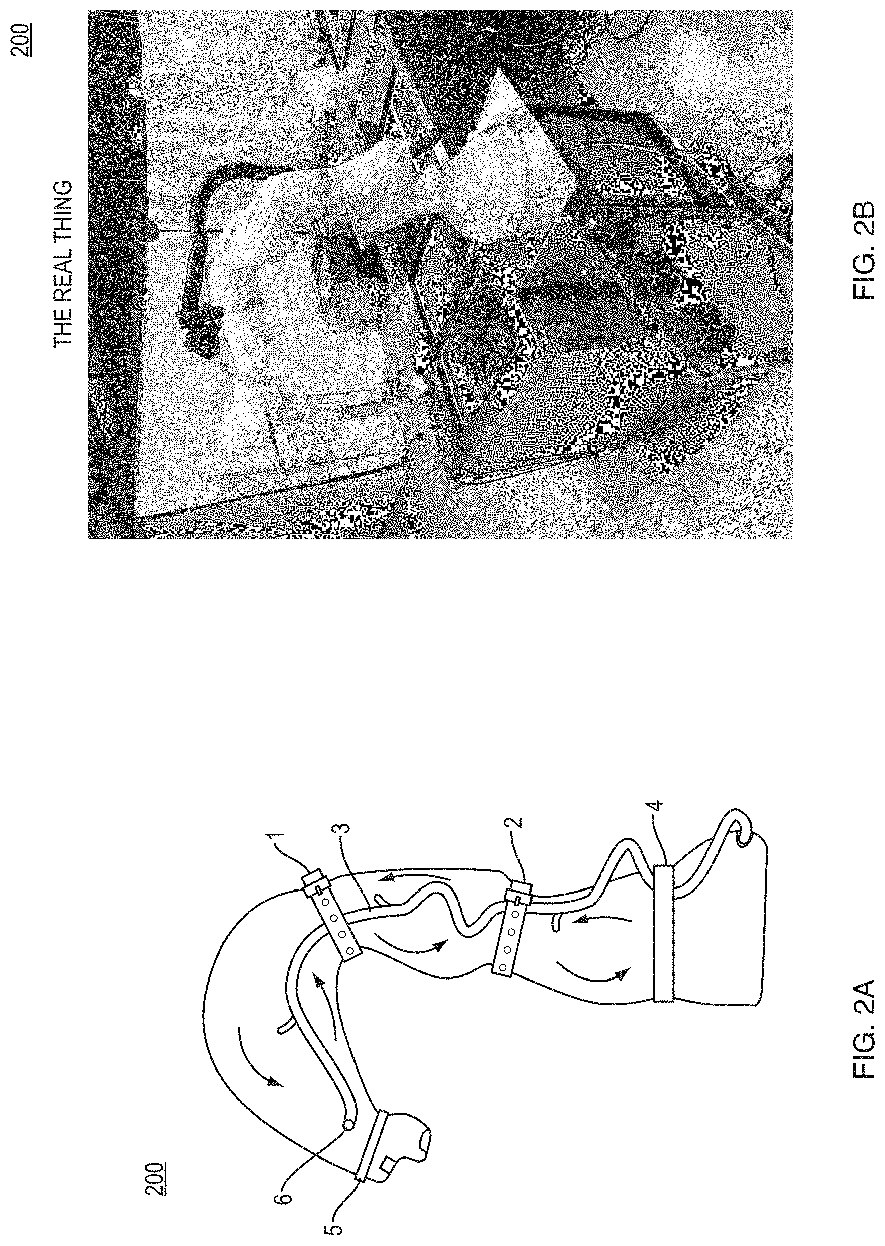
[0037] FIG. 2 is a diagram 200 of an example embodiment of a cover on a robotic arm. In an embodiment, external elastic bands or straps 1, 2 are employed to constrain cable harness 3. These straps 1, 2 are located on the top of the cover to constrain cable harness while allowing enough slack for maximum range of motion of the robot. The straps 1, 2 rest on top of the cover and on top of a support ring to allow air to flow freely inside the cover while the strap constricts the cable harness and cover. Air should move freely to inflate the non-porous elastic cover off the surface of the robot, and allow the robot to move with minimal constriction. Moving air through the system allows for heat management. In addition, the cover can be made out of latex, which can be sufficiently thermally conductive, if the material is thin enough to provide limited thermal resistance. Elastic constraints 4 and 5 are elastic portions of the cover that hold the cover to the robotic arm at the respective distal and proximal ends of the cover. Further, opening 6 allows external cabling to enter the cover.
[0038] One challenge in designing such a cover is that it is difficult to design and fabricate a cover which is able to allow the robot to operate all joints through their full ranges of motion. Certain configurations may constrict the robot or cause the cover material to tear or rupture. To fabricate a cover that allows the robot to operate through its full range of motion durably (e.g., nonbreakably or without breaking), a pattern of over 100 pieces are welded together using latex glue. The pattern is designed such that the cover is tight where the motion of the robot requires minimal change in the cover dimensions, and additional material is present in regions where robot joint motion requires substantial changes in the cover geometry. This approach results in a cover which supports any combination of joint angles for an up to 7-degree of freedom robot. Each elastic material is configured to stretch and contract in accordance with the range of motion of the robotic arm that it covers. In order to accommodate the motion of an articulated robot, the cover is designed to be form-fitting to the geometry of the robot, then regions of large motion are identified, and the local geometry is expanded such that the cover geometry is oversized so that including the stretch induced by the fabric, the total additional joint torque exerted by the cover is less than the maximum gravity compensation torque required for that joint at the maximum load capacity of the robot.
[0039] In an embodiment, the cover for an automated robot includes elastic sheets that are adhered to each other in a geometry. The geometry is configured to allow the elastic sheets to expand and contract while the automated robot moves within its range of motion. The elastic sheets are attached to the automated robot by elasticity of the elastic sheets. A first group of the elastic sheets forms an elastic collar 4 and 5 configured to grip the automated robot at a distal end and a proximal end of the cover.
[0040] FIG. 3 is a diagram 300 of a support ring. Support rings can serve as internal or external cable routing interfaces for elastic straps to fit on top of and not constrict media or air flow. Support rings are not strictly necessary, but can improve performance in certain embodiments. For example, without support rings, cabling can go in external tube or housing. However, with support rings 1, the cabling 7 can run through separate holes 2 in the support ring 4 internal to the robot cover 5. Cables 7 are run outside the robotic arms 6 because slip rings do not support high bandwidth applications such as streaming video from sensors located at the wrist of the robot.
[0041] A person having ordinary skill in the art can see that the support ring of FIG. 3 includes an outer support ring 2 and an inner support ring 3. The support ring further includes holes 1 that cabling and wiring can be run through.
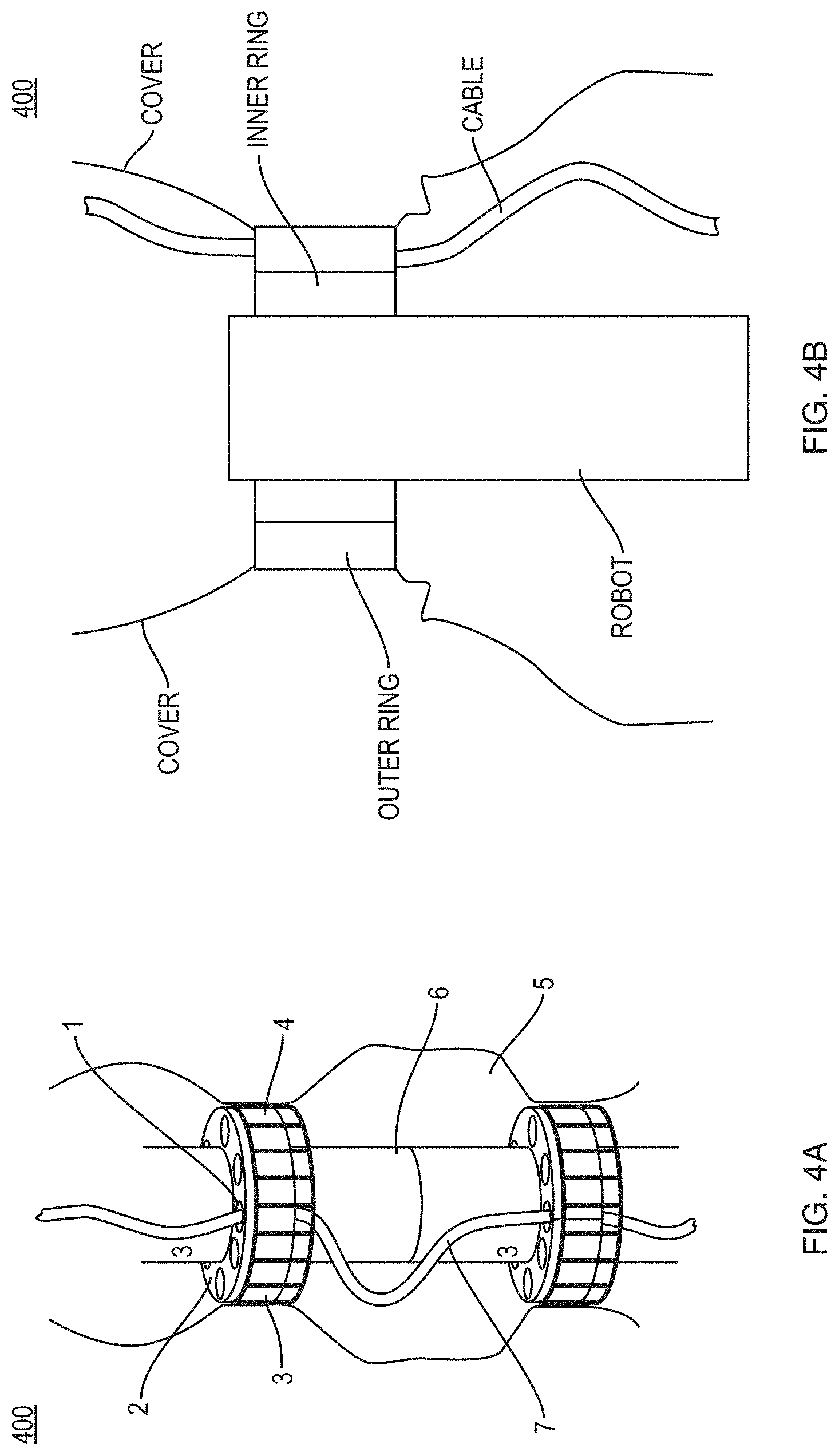
[0042] FIG. 4 is a diagram 400 of a support ring consisting of an inner, static ring 1 which is connected to the robot 6 and an outer, rotating ring 3, 4 which is connected to the inner ring 1 via a bearing. This bearing may be a ball bearing, a roller bearing, or a sleeve bearing. The elastic covering causes the outer, rotating ring 3, 4 to be fixed to fixed to the elastic covering via friction. By having a low friction, rotating interface between the cover, a tighter cover may be used as the total geometric change in the dimensions of the cover is reduced.
[0043] The teachings of all patents, published applications and references cited herein are incorporated by reference in their entirety.
[0044] While example embodiments have been particularly shown and described, it will be understood by those skilled in the art that various changes in form and details may be made therein without departing from the scope of the embodiments encompassed by the appended claims.
* * * * *
D00000
D00001
D00002
D00003
D00004
XML
uspto.report is an independent third-party trademark research tool that is not affiliated, endorsed, or sponsored by the United States Patent and Trademark Office (USPTO) or any other governmental organization. The information provided by uspto.report is based on publicly available data at the time of writing and is intended for informational purposes only.
While we strive to provide accurate and up-to-date information, we do not guarantee the accuracy, completeness, reliability, or suitability of the information displayed on this site. The use of this site is at your own risk. Any reliance you place on such information is therefore strictly at your own risk.
All official trademark data, including owner information, should be verified by visiting the official USPTO website at www.uspto.gov. This site is not intended to replace professional legal advice and should not be used as a substitute for consulting with a legal professional who is knowledgeable about trademark law.