Food-Safe, Washable Interface For Exchanging Tools
Johnson; David M.S. ; et al.
U.S. patent application number 16/570955 was filed with the patent office on 2020-03-19 for food-safe, washable interface for exchanging tools. The applicant listed for this patent is The Charles Stark Draper Laboratory, Inc.. Invention is credited to Cody Chu, David M.S. Johnson, Justin Rooney, Luis Trueba.
| Application Number | 20200086503 16/570955 |
| Document ID | / |
| Family ID | 68069913 |
| Filed Date | 2020-03-19 |

| United States Patent Application | 20200086503 |
| Kind Code | A1 |
| Johnson; David M.S. ; et al. | March 19, 2020 |
Food-Safe, Washable Interface For Exchanging Tools
Abstract
A problem with current food service robots is making the robots safe to work around food. A solution provided by the present disclosure is a food-safe tool switcher and corresponding tool. The tool switcher can mate with a variety of tools, which can be molded or 3D printed out of food-safe materials into a single-part, instead of constructed modularly. This provides for easier cleaning.
| Inventors: | Johnson; David M.S.; (Cambridge, MA) ; Rooney; Justin; (New York, NY) ; Chu; Cody; (Somerville, MA) ; Trueba; Luis; (San Marcos, TX) | ||||||||||
| Applicant: |
|
||||||||||
|---|---|---|---|---|---|---|---|---|---|---|---|
| Family ID: | 68069913 | ||||||||||
| Appl. No.: | 16/570955 | ||||||||||
| Filed: | September 13, 2019 |
Related U.S. Patent Documents
| Application Number | Filing Date | Patent Number | ||
|---|---|---|---|---|
| 62730703 | Sep 13, 2018 | |||
| 62730947 | Sep 13, 2018 | |||
| 62730933 | Sep 13, 2018 | |||
| 62730918 | Sep 13, 2018 | |||
| 62730934 | Sep 13, 2018 | |||
| 62731398 | Sep 14, 2018 | |||
| Current U.S. Class: | 1/1 |
| Current CPC Class: | B25J 9/1697 20130101; B25J 19/023 20130101; B25J 13/085 20130101; G05B 2219/45111 20130101; G05B 2219/39319 20130101; B25J 9/1676 20130101; G05B 2219/39468 20130101; B25J 9/1653 20130101; B25J 9/1664 20130101; B25J 9/1682 20130101; B25J 13/088 20130101; G05B 2219/39091 20130101; B25J 19/0083 20130101; G05B 2219/39342 20130101; G05B 2219/50391 20130101; B25J 13/003 20130101; G05B 2219/40201 20130101; B25J 9/0009 20130101; G05D 1/02 20130101; B23Q 3/15503 20161101; B25J 15/0052 20130101; H04L 67/12 20130101; G05B 19/4061 20130101; G05B 2219/39001 20130101; G06N 3/08 20130101; B25J 9/1633 20130101; B25J 9/1666 20130101; G05B 2219/32335 20130101; G05B 2219/40202 20130101; B25J 15/0408 20130101; B65G 1/137 20130101; G05B 2219/40497 20130101; G06Q 10/06316 20130101; B25J 9/1674 20130101; B25J 9/161 20130101; G05B 2219/40411 20130101; A47J 44/00 20130101; B25J 11/0045 20130101; G05B 2219/49157 20130101; G10L 15/22 20130101; G06K 9/00355 20130101 |
| International Class: | B25J 15/04 20060101 B25J015/04; B25J 11/00 20060101 B25J011/00 |
Claims
1. A system comprising: an actuating rod; at least one ball bearing; a housing having a first port to receive the actuating rod, and having a second port within the first port to receive the at least one ball bearing, the first port and second port of the housing configured to allow motion of the actuating rod in a direction through the first port perpendicular to the at least one ball bearing in the second port, a distal end of the second port further having a hole with a constriction on the outer circumference of the housing, the constriction configured to allow a portion of the ball bearing to extend out of the second port while holding the remaining portion of the ball bearing within the second port; a utensil mating bracket having a reception port configured to receive the housing, the reception port having at least one locking member along an outer portion of the reception port, such that when the portion of the at least one ball bearing extends out of the second port, the locking member interfaces with the portion of the at least one ball bearing such that the housing is locked within the utensil mating bracket.
2. The system of claim 1, further comprising: a compression spring within the housing, the compression spring coupled with the actuating rod.
3. The system of claim 1, wherein the actuating rod is configured to extend through the housing such that it forces the at least one ball bearing through the second port such that the portion of the ball bearing extends out of the second port.
4. The system of claim 1, wherein the first port and second port have consistent diameters throughout lengths of the respective first and second ports.
5. The system of claim 1, wherein: the at least one ball bearing is at least two ball bearings, the housing includes a third port within the first port to receive a second of the at least two ball bearings, the third port of the housing configured to allow motion of the second ball bearing perpendicular to the motion of the actuating rod in the first port, a distal end of the third port further having hole with a constriction on the outer circumference of the housing, the constriction configured to allow a portion of the second ball bearing to extend out of the third port while holding the remaining portion of the second ball bearing within the third port; wherein when the portion of the second ball bearing extends out of the third port, the locking member interfaces with the portion of the at least one ball bearing such that the housing is locked within the utensil mating bracket.
6. The system of claim 1, wherein the utensil mating bracket further includes an actuator port configured to receive an actuator.
7. The system of claim 6, wherein the actuator is a rotary actuator.
8. The system of claim 6, wherein the actuator is configured to actuate a tool coupled with the utensil mating bracket.
9. The system of claim 8, wherein the actuator port is a pneumatic port configured to provide air pressure to the tool in response to a command.
10. A method comprising: providing an actuating rod, at least one ball bearing, and a housing; receiving the actuating rod at a first port of the housing; receiving, at a second port within the first port, the at least one ball bearing; wherein the first port and second port of the housing are configured to allow motion of the actuating rod in a direction through the first port perpendicular to the at least one ball bearing in the second port, a distal end of the second port further having a hole with a constriction on the outer circumference of the housing, the constriction configured to allow a portion of the ball bearing to extend out of the second port while holding the remaining portion of the ball bearing within the second port; receiving the housing at a utensil mating bracket having a reception port, the reception port having at least one locking member along an outer portion of the reception port, such that when the portion of the at least one ball bearing extends out of the second port, the locking member interfaces with the portion of the at least one ball bearing such that the housing is locked within the utensil mating bracket.
Description
RELATED APPLICATIONS
[0001] This application claims the benefit of U.S. Provisional Application No. 62/730,703, filed on Sep. 13, 2018, U.S. Provisional Application No. 62/730,947, filed on Sep. 13, 2018, U.S. Provisional Application No. 62/730,933, filed on Sep. 13, 2018, U.S. Provisional Application No. 62/730,918, filed on Sep. 13, 2018, U.S. Provisional Application No. 62/730,934, filed on Sep. 13, 2018 and U.S. Provisional Application No. 62/731,398, filed on Sep. 14, 2018.
[0002] This application is related to U.S. patent application titled "Manipulating Fracturable And Deformable Materials Using Articulated Manipulators", Attorney Docket No. 5000.1049-001; U.S. patent application titled "Food-Safe, Washable, Thermally-Conductive Robot Cover", Attorney Docket No. 5000.1050-000; U.S. patent application titled "An Adaptor for Food-Safe, Bin-Compatible, Washable, Tool-Changer Utensils", Attorney Docket No. 5000.1052-001; U.S. patent application titled "Locating And Attaching Interchangeable Tools In-Situ", Attorney Docket No. 5000.1053-001; U.S. patent application titled "Determining How To Assemble A Meal", Attorney Docket No. 5000.1054-001; U.S. patent application titled "Controlling Robot Torque And Velocity Based On Context", Attorney Docket No. 5000.1055-001; U.S. patent application titled "Stopping Robot Motion Based On Sound Cues", Attorney Docket No. 5000.1056-000; U.S. patent application titled "Robot Interaction With Human Co-Workers", Attorney Docket No. 5000.1057-001; U.S. patent application titled "Voice Modification To Robot Motion Plans", Attorney Docket No. 5000.1058-000; and U.S. patent application titled "One-Click Robot Order", Attorney Docket No. 5000.1059-000, all of the above U.S. patent applications having a first named inventor David M. S. Johnson and all being filed on the same day, Sep. 13, 2019.
[0003] The entire teachings of the above applications are incorporated herein by reference.
BACKGROUND
[0004] Traditionally, quick service food restaurants (fast food) employs humans assembling ingredients from pre-prepared bins or containers into a meal. Robots have not yet been able to assemble meals from prepared ingredients as a whole.
SUMMARY
[0005] In embodiments, the below disclosure solves problems in relation to employing a food-safe tool changer in the quick service fast food restaurant environment. This device must enable a robot to detach and attach a variety of different tools for use in assembling and processing ingredients to prepare recipes. In order to effectively use a tool, the robot must have a rigid and geometrically deterministic interface between the tool and the robot. If the tool is not located where the programmer intended it to be, the robot will use the tool incorrectly when attempting to accomplish a task. The tool may collide with other objects in the workspace, as collision detection is performed using a geometric model of the robot and the tool, requiring an accurate attachment between the tool and the robot.
[0006] In an embodiment, a system includes an actuating rod, at least one ball bearing, and a housing having a first port to receive the actuating rod, and having a second port within the first port to receive the at least one ball bearing. The first port and second port of the housing are configured to allow motion of the actuating rod in a direction through the first port perpendicular to the at least one ball bearing in the second port. A distal end of the second port further has a hole with a constriction on the outer circumference of the housing. The constriction is configured to allow a portion of the ball bearing to extend out of the second port while holding the remaining portion of the ball bearing within the second port. The system further includes a utensil mating bracket having a reception port configured to receive the housing. The reception port having at least one locking member along an outer portion of the reception port, such that when the portion of the at least one ball bearing extends out of the second port, the locking member interfaces with the portion of the at least one ball bearing such that the housing is locked within the utensil mating bracket.
[0007] In an embodiment, the system further includes a compression spring within the housing. The compression spring is coupled with the actuating rod.
[0008] In an embodiment, the actuating rod is configured to extend through the housing such that it forces the at least one ball bearing through the second port such that the portion of the ball bearing extends out of the second port.
[0009] In an embodiment, the first port and second port have consistent diameters throughout lengths of the respective first and second ports.
[0010] In an embodiment, the at least one ball bearing is at least two ball bearings. The housing includes a third port within the first port to receive a second of the at least two ball bearings. The third port of the housing is configured to allow motion of the second ball bearing perpendicular to the motion of the actuating rod in the first port. A distal end of the third port further has hole with a constriction on the outer circumference of the housing. The constriction is configured to allow a portion of the second ball bearing to extend out of the third port while holding the remaining portion of the second ball bearing within the third port. When the portion of the second ball bearing extends out of the third port, the locking member interfaces with the portion of the at least one ball bearing such that the housing is locked within the utensil mating bracket.
[0011] In an embodiment, the utensil mating bracket further includes an actuator port configured to receive an actuator. The actuator can be a rotary actuator. The actuator can be configured to actuate a tool coupled with the utensil mating bracket. The actuator port can be a pneumatic port configured to provide air pressure to the tool in response to a command.
[0012] In an embodiment, a method includes providing an actuating rod, at least one ball bearing, and a housing. The method further includes receiving the actuating rod at a first port of the housing. The method further includes receiving, at a second port within the first port, the at least one ball bearing. The first port and second port of the housing are configured to allow motion of the actuating rod in a direction through the first port perpendicular to the at least one ball bearing in the second port. A distal end of the second port further has a hole with a constriction on the outer circumference of the housing. The constriction is configured to allow a portion of the ball bearing to extend out of the second port while holding the remaining portion of the ball bearing within the second port. The method further includes receiving the housing at a utensil mating bracket having a reception port. The reception port has at least one locking member along an outer portion of the reception port, such that when the portion of the at least one ball bearing extends out of the second port. The locking member can interface with the portion of the at least one ball bearing such that the housing is locked within the utensil mating bracket.
BRIEF DESCRIPTION OF THE DRAWINGS
[0013] The foregoing will be apparent from the following more particular description of example embodiments, as illustrated in the accompanying drawings in which like reference characters refer to the same parts throughout the different views. The drawings are not necessarily to scale, emphasis instead being placed upon illustrating embodiments.
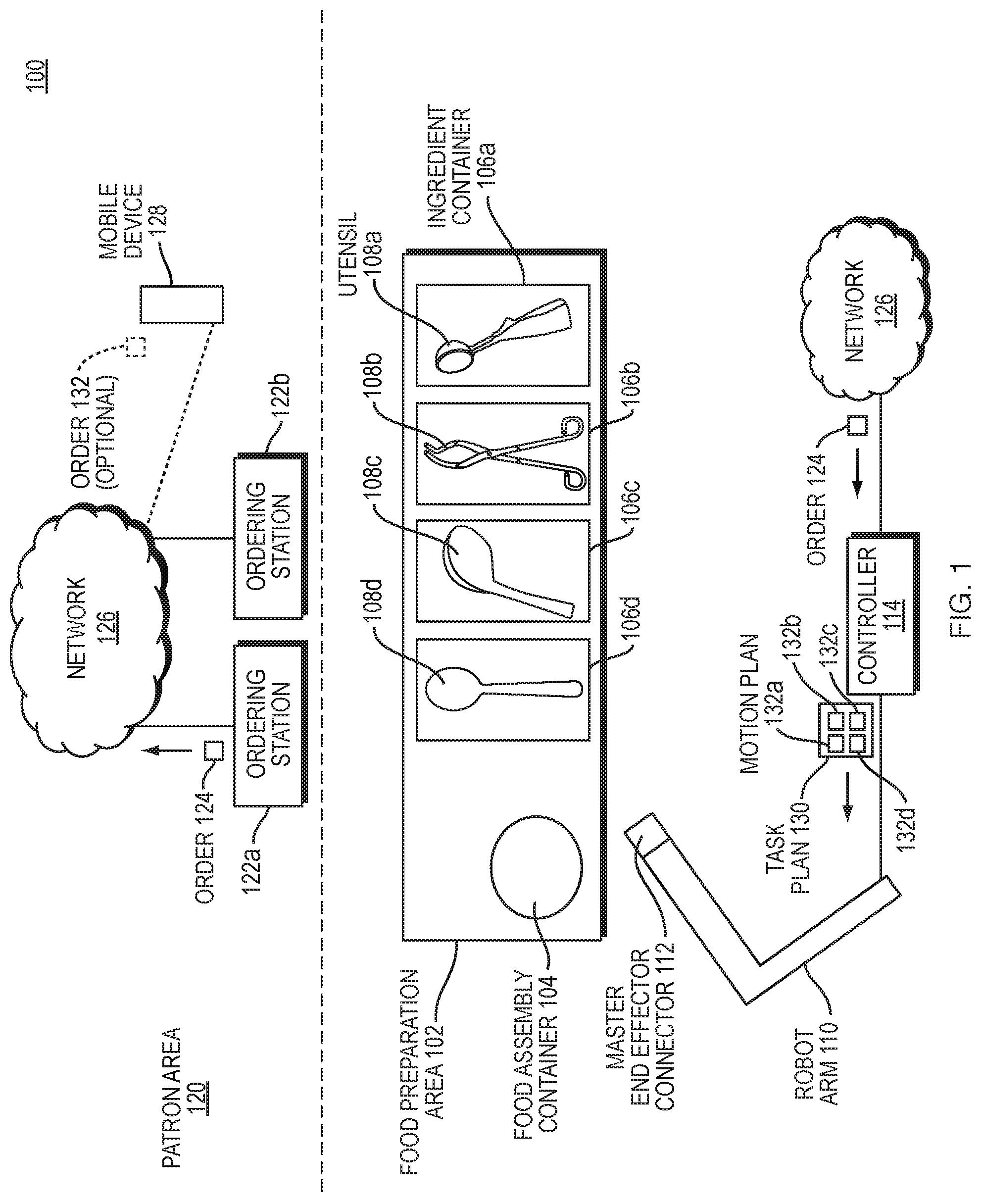
[0014] FIG. 1 is a block diagram illustrating an example embodiment of a quick service food environment of embodiments of the present invention.
[0015] FIG. 2A is a diagram illustrating an isometric view of a tool changer in a locked position where an actuating rod is extended such that ball bearings 4 are expanded outwards.
[0016] FIG. 2B is a diagram illustrating an isometric view of a tool changer in the unlocked position.
[0017] FIG. 3 is a diagram illustrating a side view of a tool position in a locked position, as described in FIG. 1.
[0018] FIG. 4 is a diagram illustrating a side view of an unlocked position as described in FIG. 2.
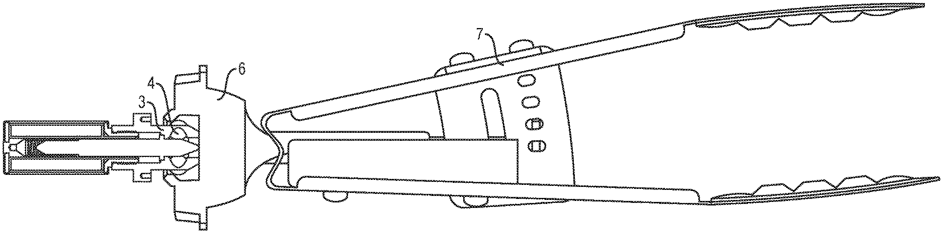
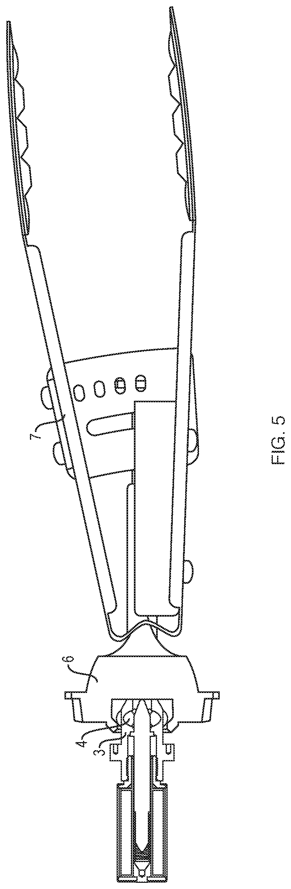
[0019] FIG. 5 is a diagram illustrating an example tool mated with the tool changer in the locked position.
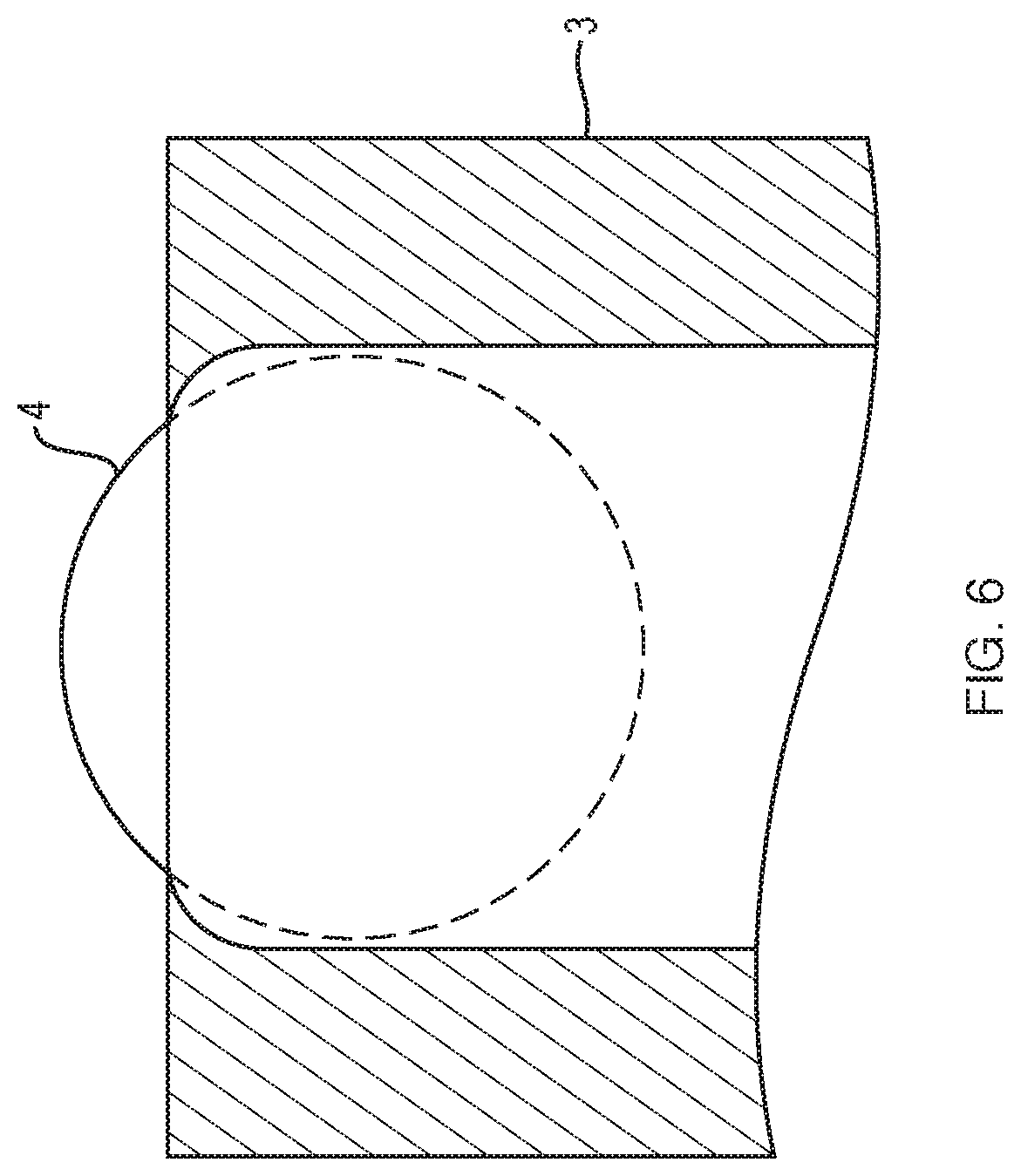
[0020] FIG. 6 is a diagram illustrating ball bearings being held captive in the ball bearing housing.
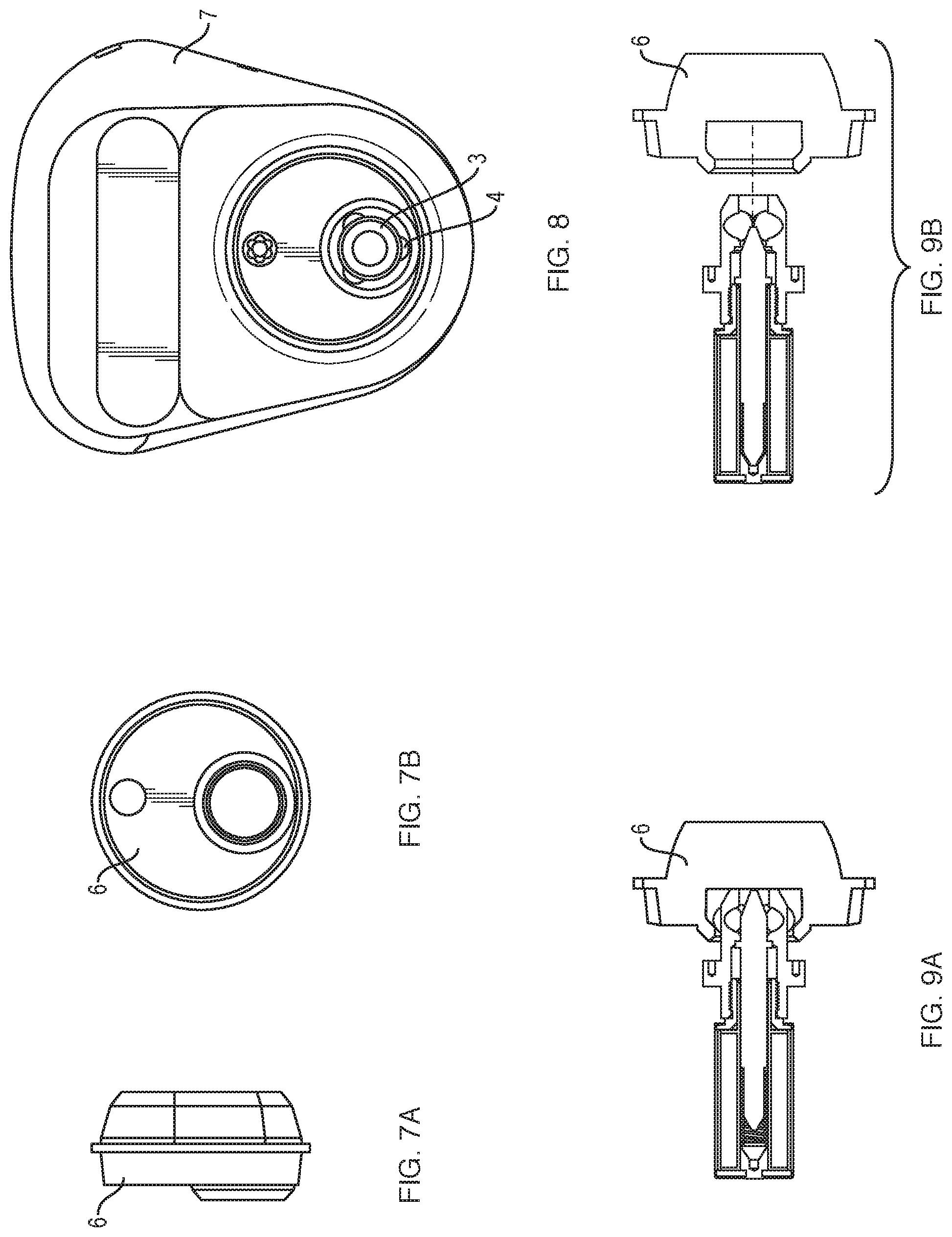
[0021] FIG. 7A is a diagram illustrating a side view of compliant and locating features included in a utensil mounting bracket.
[0022] FIG. 7B is a diagram illustrating a front view of compliant and locating features included in a utensil mounting bracket.
[0023] FIG. 8 illustrates an end-effector cover that provides locational and compliance features to draw the utensil mounting bracket into the correct position.
[0024] FIG. 9A is a diagram illustrating a locked position of the tool changer mating with the utensil mounting bracket.
[0025] FIG. 9B is a diagram illustrating an unlocked position of the tool changer mating with the utensil mounting bracket.
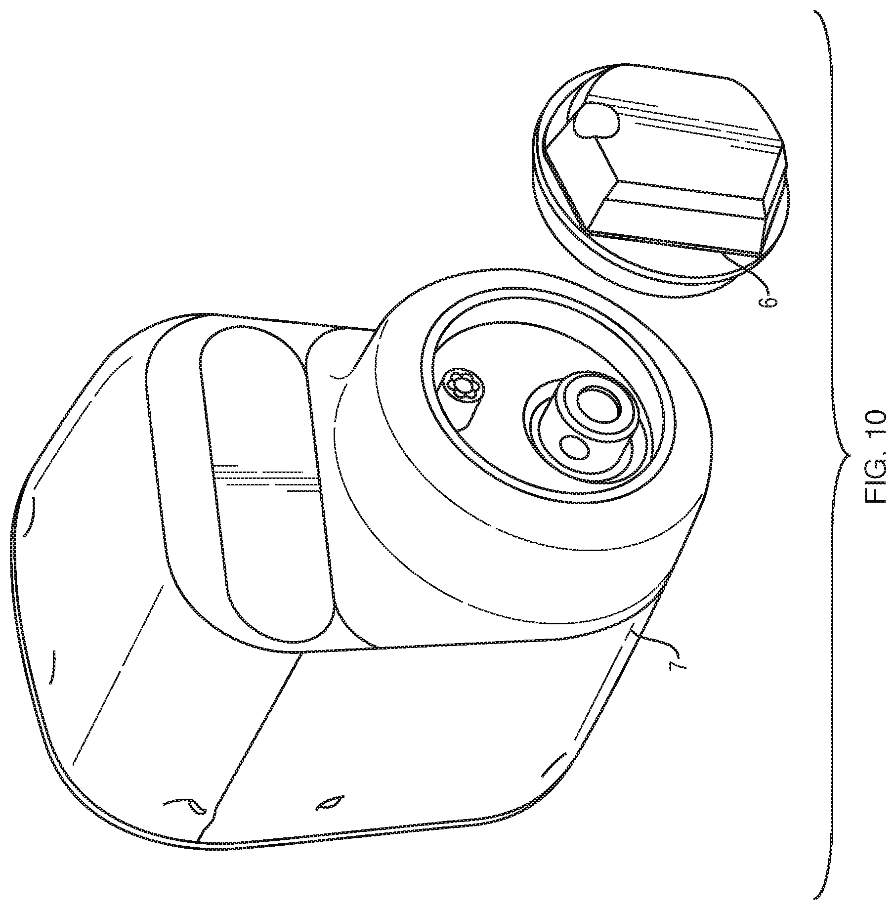
[0026] FIG. 10 is an exploded view diagram illustrating a mating paradigm between the utensil mounting bracket and an end-effector cover.
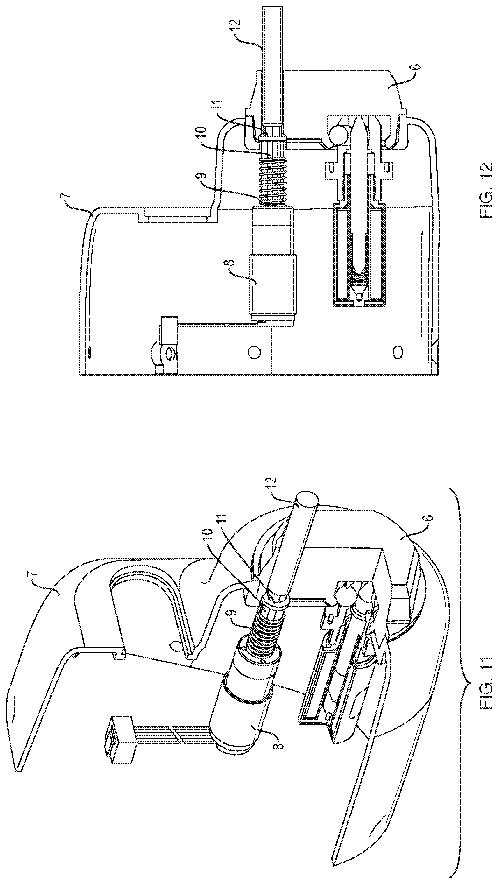
[0027] FIG. 11 is a diagram illustrating a rotary actuator packaged alongside the tool changer.
[0028] FIG. 12 is a diagram illustrating the rotary actuator from a different view.
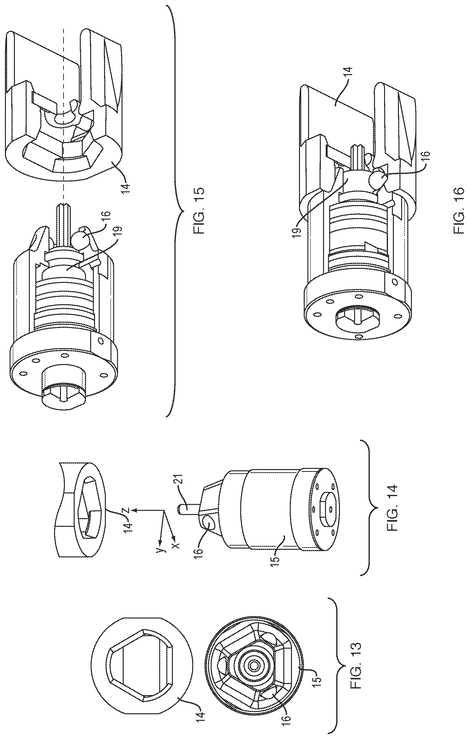
[0029] FIG. 13 is a diagram illustrating an additional geometry for constraining the utensils.
[0030] FIG. 14 is a diagram illustrating another tool changer geometry.
[0031] FIG. 15 is an exploded view diagram illustrating a mating paradigm between tool changer and utensil mounting bracket
[0032] FIG. 16 is a diagram illustrating the tool changer in the locked position. Tool changer actuation rod 19 is in an extended position expanding ball bearings outwards.
[0033] FIG. 17 is a diagram illustrating an exploded view of a second tool changer.
[0034] FIG. 18 is a cross-sectional diagram illustrating the second tool changer geometry.
[0035] FIGS. 19A-D are diagrams illustrating the function of the tool changer's internal actuation scheme.
DETAILED DESCRIPTION
[0036] A description of example embodiments follows.
[0037] Operating a robot in a food preparation environment, such as a quick service restaurant, can be challenging for several reasons. First, the end effectors (e.g., utensils), that the robot uses need to remain clean from contamination. Contamination can include allergens (e.g., peanuts), dietary preferences (e.g., contamination from pork for a vegetarian or kosher customer), dirt/bacteria/viruses, or other non-ingestible materials (e.g., oil, plastic, or particles from the robot itself). Second, the robot should be operated within its design specifications, and not exposed to excessive temperatures or incompatible liquids, without sacrificing cleanliness. Third, the robot should be able to manipulate food stuffs, which are often fracturable and deformable materials, and further the robot must be able to measure an amount of material controlled by its utensil in order to dispense specific portions. Fourth, the robot should be able to automatically and seamlessly switch utensils (e.g., switch between a ladle and salad tongs). Fifth, the utensils should be adapted to be left in an assigned food container and interchanged with the robot as needed, in situ. Sixth, the interchangeable parts (e.g., utensils) should be washable and dishwasher safe. Seventh, the robot should be able to autonomously generate a task plan and motion plan(s) to assemble all ingredients in a recipe, and execute that plan. Eighth, the robot should be able to modify or stop a motion plan based on detected interference or voice commands to stop or modify the robot's plan. Ninth, the robot should be able to minimize the applied torque based on safety requirements or the task context or the task parameters (e.g., density and viscosity) of the material to be gathered. Tenth, the system should be able to receive an electronic order from a user, assemble the meal for the user, and place the meal for the user in a designated area for pickup automatically with minimal human involvement.
[0038] FIG. 1 is a block diagram illustrating an example embodiment of a quick service food environment 100 of embodiments of the present disclosure. The quick service food environment 100 includes a food preparation area 102 and a patron area 120.
[0039] The food preparation area 102 includes a plurality of ingredient containers 106a-d each having a particular foodstuff (e.g., lettuce, chicken, cheese, tortilla chips, guacamole, beans, rice, various sauces or dressings, etc.). Each ingredient container 106a-d stores in situ its corresponding ingredients. Utensils 108a-d may be stored in situ in the ingredient containers or in a stand-alone tool rack 109. The utensils 108a-d can be spoons, ladles, tongs, dishers (scoopers), spatulas, or other utensils. Each utensil 108a-e is configured to mate with and disconnect from a tool changer interface 112 of a robot arm 110. While the term utensil is used throughout this application, a person having ordinary skill in the art can recognize that the principles described in relation to utensils can apply in general to end effectors in other contexts (e.g., end effectors for moving fracturable or deformable materials in construction with an excavator or backhoe, etc.); and a robot arm can be replaced with any computer controlled actuatable system which can interact with its environment to manipulate a deformable material. The robot arm 110 includes sensor elements/modules such as stereo vision systems (SVS), 3D vision sensors (e.g., Microsoft Kinect.TM. or an Intel RealSense.TM.), LIDAR sensors, audio sensors (e.g., microphones), inertial sensors (e.g., internal motion unit (IMU), torque sensor, weight sensor, etc.) for sensing aspects of the environment, including pose (i.e., X, Y, Z coordinates and roll, pitch, and yaw angles) of tools for the robot to mate, shape and volume of foodstuffs in ingredient containers, shape and volume of foodstuffs deposited into food assembly container, moving or static obstacles in the environment, etc.
[0040] To initiate an order, a patron in the patron area 120 enters an order 124 in an ordering station 122a-b, which is forwarded to a network 126. Alternatively, a patron on a mobile device 128 can, within or outside of the patron area 120, generate an optional order 132. Regardless of the source of the order, the network 126 forwards the order to a controller 114 of the robot arm 110. The controller generates a task plan 130 for the robot arm 110 to execute.
[0041] The task plan 130 includes a list of motion plans 132a-d for the robot arm 110 to execute. Each motion plan 132a-d is a plan for the robot arm 110 to engage with a respective utensil 108a-e, gather ingredients from the respective ingredient container 106a-d, and empty the utensil 108a-e in an appropriate location of a food assembly container 104 for the patron, which can be a plate, bowl, or other container. The robot arm 110 then returns the utensil 108a-e to its respective ingredient container 106a-d, the tool rack 109, or other location as determined by the task plan 130 or motion plan 132a-d, and releases the utensil 108a-d. The robot arm executes each motion plan 132a-d in a specified order, causing the food to be assembled within the food assembly container 104 in a planned and aesthetic manner.
[0042] Within the above environment, various of the above described problems can be solved. The environment 100 illustrated by FIG. 1 can improve food service to patrons by assembling meals faster, more accurately, and more sanitarily than a human can assemble a meal. Some of the problems described above can be solved in accordance with the disclosure below.
[0043] Tool changers allow one mechanical robot or robot arm to exchange end effectors, and therefore be used for a variety of different purposes. For example, a robot arm with the ability to change end effectors can both grab an item with a claw and scoop an item with a scooper tool. The industry standard for tool changers does not provide product lines or models targeted at the food service industry, however. Available tool changer masters typically employ a metallic design for higher load industrial applications.
[0044] The present disclosure describes a food-safe tool changer that is constructed from low-load, food-safe materials. The disclosure further provides a degree of compliance to allow some misalignment when tool mating, which assists with automated tool mating. The invention further provides a food-safe shield to any accoutrements aimed at assisting the functionality of the tool changer master. A food-safe tool changer does not discard materials/shavings into the food, does not user non-edible lubricants, and all materials used are non-poisonous and/or edible.
[0045] For a robot arm to perform a task are traditionally configured with a specialized tool mounted to the end of the arm, referred to as an end-effector. Tasks also usually require more than one tool, and robots often are equipped with a flange that allows rapidly exchanging end-effectors. The flange is known as a tool-changer (see ATI Industrial Automation, etc.). Tool-changers are usually stiff, mechanically robust, able to be locked and un-locked using a remote actuation mechanism, and compatible with the environmental requirements of the task. In the restaurant embodiments of the present disclosure, the environmental requirements include being wash-down compatible food safe, and able to handle high temperatures, and other food-specific requirements.
[0046] Tool-changing has been around for as long as machine tools. Many tool changing standards currently exist for CNC (computer numerical control) machines with automatic tool changers (ATC).
[0047] Due to challenges of programming robot motion, much of the task complexity is often placed in the end-effector. Therefore, end-effectors are often complicated and contain many actuatable mechanisms and sensors. For the end-effectors to be exchangeable, existing tool changers contain a single mechanical locking mechanism and many pneumatic and electrical signal carrying accoutrements to pass to the tool.
[0048] Due to their complexity, these tools are expensive to develop and manufacture at scale. The goal of the present disclosure is to enable tool changing between tools that require actuation, without needing an actuator to be packaged on the tool side. Such a design removes complexity from each tool by adding features to the tool-changer master (e.g., the component which remains attached to the robot). The disclosed invention adds a nested configurable drive shaft with rotational capabilities that is linked to a linear shaft which actuates the locking mechanism, in a similar fashion to existing tool-changers. This approach replaces electrical and pneumatic feedthroughs with a single additional mechanical connection, which reduces the tool complexity and thus drastically reducing the cost of the tool side implements. In effect, this approach enables robot to employ tools that are more replaceable or disposable, economically in-line with traditional kitchen utensils (e.g., spatulas, tongs, dishers, and spoons).
[0049] In addition to the problem described above, the industry standard for tool changers does not contain a product line targeted at the food service industry. Available tool changer masters typically utilize materials that are not food-safe and are not protected against foreign material ingress (e.g., food clogging the mechanism). The invention described is constructed from food-safe materials and contains various sealing features that protect from ingress and enable wash-down cleaning.
[0050] The present disclosure illustrates and describes two tool changer designs below. A first design is illustrated in FIGS. 2A-12. The first tool changer design employs an eccentric circle features to constrain the tool in the yaw axis (e.g., around the z-axis). The first tool changer design is illustrated with electric actuation. The first tool changer design is illustrated having an actuator packaged offset from the tool changer.
[0051] The second design is illustrated in FIGS. 13-19. The second design employs tetrahedral features to constrain a yaw axis (e.g., around the z-axis). The second design constraints other axes similarly to traditionally available tool changers. The second tool changer design is illustrated with pneumatic actuation. The second tool changer design is illustrated having a linear actuator packaged internal to the tool changer.
[0052] While the first and second tool changer design are described as above, a person having ordinary skill in the art may combine various features described herein of both designs into other designs to create other tool changer designs.
[0053] FIG. 2A is a diagram illustrating an isometric view of a tool changer in a locked position where an actuating rod 5 is extended such that ball bearings 4 are expanded outwards. Compression spring 1 keeps the tool changer in this position during normal operation, which is advantageous to keep the ball bearing holes plugged for cleanability while the system is powered off and, in event of a power outage, to keep the tool attached to the robot. Ball bearing housing 3 holds the ball bearings captive and allows them to move into the locked and unlocked position without falling out of the housing. Ball hearing housing 3 also contains mounting features and compliant features that are described in further detail below.
[0054] FIG. 2B is a diagram illustrating an isometric view of a tool changer in the unlocked position. The actuating rod 5 is retracted through the electrical activation of solenoid 2.
[0055] FIG. 3 is a diagram illustrating a side view of a tool position in a locked position, as described in FIG. 1.
[0056] FIG. 4 is a diagram illustrating a side view of an unlocked position as described in FIG. 2.
[0057] FIG. 5 is a diagram illustrating an example tool mated with the tool changer in the locked position. Ball bearings 4 are engaged with the internal race feature of a tool mounting bracket 6. A tongs assembly 7 can be used for handling foodstuffs and can be interchanged with various other utensil assemblies.
[0058] FIG. 6 is a diagram illustrating ball bearings 4 being held captive in the ball bearing housing 3. The hole is a consistent diameter internally to allow the ball to move back and forth. The distal end of the hole includes a constriction in the hole diameter that prevents the balls from escaping. A person having ordinary skill in the art can recognize that when the actuator rod is pushed into an extended position, the ball bearings extend through the distal end of the hold and protrude through the housing. With the ball bearings protruding through the housing, as shown in FIG. 9A and described in further detail below, the housing of the actuator rod is locked within a utensil mating bracket.
[0059] FIG. 7A is a diagram illustrating a side view of compliance and locational features included in a utensil mounting bracket 6. FIG. 7A on the left-hand side illustrates a tapered geometry that allows sloped surfaces to act as cams with the mating piece to draw into the locked position.
[0060] FIG. 7B is a diagram illustrating a front view of compliant and locating features included in a utensil mounting bracket 6. Eccentric circles formed by the outer diameter and the tool changer race of utensil mounting bracket 6 locate the utensil mounting bracket 6 rotationally in the yaw direction.
[0061] FIG. 8 illustrates an end-effector cover 7 that provides locational and compliance features to draw the utensil mounting bracket 6 into the correct position. The ball bearing housing 3 coupled with the circular outer diameter feature in the utensil mounting bracket 6 enable full constraint of the utensil. The tapered side wall features of end-effector housing 7 and recessed circular feature of utensil mounting bracket 6 outer diameter are compliant because bracket 6 can be misaligned positionally and rotationally from the central axis of the ball bearing housing along the z-axis, but still be mated properly upon approach.
[0062] FIG. 9A is a diagram illustrating a locked position of the tool changer mating with the utensil mounting bracket 6. As is shown, the actuator rod forces the ball bearings through their respective holes in the bearing housing to protrude and mate with the race of utensil mounting bracket 6. The ball bearings extend such that a lip, or restrictive member, of the utensil mating bracket, locks the housing of the actuator rod into place.
[0063] FIG. 9B is a diagram illustrating an unlocked position of the tool changer mating with the utensil mounting bracket 6. To unlock the housing of the actuator rod, the actuator rod should be receded within the housing (e.g., through reducing tension on the spring via the solenoid or other means). The ball bearings then recede within the housing, and the housing is no longer locked within the utensil mating bracket.
[0064] FIG. 10 is an exploded view diagram illustrating a mating paradigm between the utensil mounting bracket 6 end-effector cover 7.
[0065] FIG. 11 is a diagram illustrating a rotary actuator packaged alongside the tool changer. A motor 8 may include a gearbox, encoder, or both. Spring 9 provides compliant coupling with a utensil driveshaft 12 to transfer rotational power, while remaining severable (e.g., disconnectable). Dog interfaces 10 and 11 (e.g., a dog clutch) enable removable rotational power transfer through use of a dog clutch mechanism.
[0066] FIG. 12 is a diagram illustrating the rotary actuator packaged alongside the tool changer from a different view.
[0067] FIG. 13 is a diagram illustrating an additional geometry for constraining the utensils. The geometry is tetrahedral and the top is cut along an xy plane (see, e.g., FIG. 14's x-y-z triad for reference of the x-y plane in relation to the three-dimensional view of FIG. 14). A utensil mating bracket 14 has an internal race to accept ball bearings 16 to constrain in all degrees of freedom. Ball bearing housing 15 holds the ball bearings 16 captive and allows them to move into the locked and unlocked position without falling out of the housing. The holes for the ball bearings use similar features as is described in FIG. 6.
[0068] FIG. 14 is a diagram illustrating a different view of the same geometry shown in FIG. 13. The tetrahedral male feature of the ball bearing housing 15 accepts the tetrahedral female feature 14. This feature of the ball bearing housing 15 is compliant because the tetrahedral female feature 14 can be misaligned positionally and rotationally from the z-axis of the ball bearing housing, but still be mated properly upon approach.
[0069] FIG. 15 is a diagram illustrating a tool changer in an unlocked position. A tool changer actuation rod 19 is illustrated in a retracted position allowing ball bearings 16 to move inwards and enabling mating of a utensil mounting bracket 14. Tool changer actuation rod 19 is powered by air in the illustration of FIG. 19, but a person having ordinary skill in the art can understand that an electrically actuated version can be provided.
[0070] FIG. 16 is a diagram illustrating the tool changer in the locked position. Tool changer actuation rod 19 is in an extended position expanding ball bearings 16 outwards. The ball bearings extend such that a lip, or restrictive member, of the utensil mating bracket, locks the housing of the actuator rod into place.
[0071] FIG. 17 is a diagram illustrating an exploded view of a second tool changer. FIG. 18 is a cross-sectional diagram illustrating the second tool changer geometry. The outer actuation enabling the locking and unlocking of tools functions as follows. Ball bearing housing 15 and ball bearings 16 are described above. The tool changer unlock fitting 17 connects to a source of compressed air that actuates the tool changer actuation rod 19 into the unlocked position. The tool changer lock fitting 29 connects to a source of compressed air to drive the tool changer actuation rod 19 into the locked position, pushing the ball bearings 16 outwards and constraining a tool in place. Tool changer actuation rod dynamic o-rings 20 form a redundant seal to allow air actuation of the tool changer actuation rod 19. Ball bearing housing outer piston seal static o-ring 32 seals the piston from the environment and enables air actuation without leakage. Outer plug 28 is a plug that seals the outer piston from the environment through use of outer plug static o-ring outer 27 and outer plug static o-ring inner 30 and enables air actuation without leakage. Outer plug 28 enables assembly and mounting of the tool changer to an end effector housing.
[0072] Following FIG. 17 and FIG. 18, the inner actuation enabling the opening and closing of tongs functions as follows. Utensil actuation rod 21 screws into utensil actuation rod seal bracket 23. Utensil actuation rod seal bracket dynamic o-rings 22 form a redundant seal to enable air actuation of utensil actuation rod seal bracket 23 and utensil actuation rod 21, which are coupled together. Inner plug 25 seals the inner piston from the environment through use of utensil actuation rod static o-ring 31 and inner plug static o-ring 24. Inner plug 25 enables assembly of the inner components to be inserted within tool changer actuation rod 19. Other drive mechanisms could conceivably be inserted in this location, such as an electric motor or pneumatic rotary actuator. Utensil actuation fitting 26 connects to a source of compressed air that drives utensil actuation rod 21 and actuation rod seal bracket 23 outwards. Utensil actuation rod static o-ring 31 provides a seal on the top end of utensil actuation rod 21. A compression spring 33 is used to place utensil actuation rod seal bracket 23 and utensil actuation rod 21 normally in the retracted position. A linear, food-grade bearing 18 supports utensil actuation rod 21 and provides a guard from foodstuffs from entering the assembly.
[0073] FIGS. 19A-D are diagrams illustrating the functionality of the tool changer's internal actuation scheme. FIG. 19A is a diagram illustrating an example utensil (e.g., tongs) in an unactuated, normally-closed position. The tongs are kept normally-closed through the use of flexure structures on the sides of utensil mounting bracket 14. FIG. 19B is a diagram illustrating the tool changer with utensil actuation rod 21 retracted, allowing the tongs to be closed. The actuation rod 21 is normally-retracted due to the compression spring 19 shown in FIG. 17 and FIG. 18.
[0074] FIG. 19C illustrates the example utensil (e.g., tongs) open in the actuated position. FIG. 19D illustrates the tool changer having compressed air pushing the utensil actuation rod 21 outwards to move the tongs into the open position. The tool changer actuation rod 21 is removable from tongs extension rod 34 keeping the actuation on the maser side of the tool changer. When pushing outwards, power is transferred through hinge mechanism assembly 35 to open tongs 36.
[0075] The teachings of all patents, published applications and references cited herein are incorporated by reference in their entirety.
[0076] While example embodiments have been particularly shown and described, it will be understood by those skilled in the art that various changes in form and details may be made therein without departing from the scope of the embodiments encompassed by the appended claims.
* * * * *
D00000
D00001
D00002
D00003
D00004
D00005
D00006
D00007
D00008
D00009
XML
uspto.report is an independent third-party trademark research tool that is not affiliated, endorsed, or sponsored by the United States Patent and Trademark Office (USPTO) or any other governmental organization. The information provided by uspto.report is based on publicly available data at the time of writing and is intended for informational purposes only.
While we strive to provide accurate and up-to-date information, we do not guarantee the accuracy, completeness, reliability, or suitability of the information displayed on this site. The use of this site is at your own risk. Any reliance you place on such information is therefore strictly at your own risk.
All official trademark data, including owner information, should be verified by visiting the official USPTO website at www.uspto.gov. This site is not intended to replace professional legal advice and should not be used as a substitute for consulting with a legal professional who is knowledgeable about trademark law.