Determining Lifting Events Using Sensors For Person Lifting Apparatuses
Wiggermann; Neal ; et al.
U.S. patent application number 16/576069 was filed with the patent office on 2020-03-19 for determining lifting events using sensors for person lifting apparatuses. This patent application is currently assigned to Liko Research & Development AB. The applicant listed for this patent is Liko Research & Development AB. Invention is credited to Jackie Berkebile, Susan Kayser, Sravan Mamidi, Jacob Peugh, Melissa Stancato, Derek Strassle, Neal Wiggermann, Jie Zhou.
| Application Number | 20200085657 16/576069 |
| Document ID | / |
| Family ID | 69773723 |
| Filed Date | 2020-03-19 |


View All Diagrams
| United States Patent Application | 20200085657 |
| Kind Code | A1 |
| Wiggermann; Neal ; et al. | March 19, 2020 |
DETERMINING LIFTING EVENTS USING SENSORS FOR PERSON LIFTING APPARATUSES
Abstract
A method of determining a lifting event of a person lifting apparatus is provided. The method includes receiving one or more of (i) current load information from a current measuring device that is indicative of current drawn by an actuator operatively connected to a lifting strap of the person lifting apparatus; (ii) strap position information from a position sensor that is indicative of a paid out length of the lifting strap of the person lifting apparatus; and (iii) weight information from a weight sensor that is indicative of a load supported by the lifting strap of the person lifting apparatus. A computing device comprising a processor using logic is used to identify at least one of a raising event, a repositioning event and a lowering event based on the one or more of the current load information, strap position information and weight information.
| Inventors: | Wiggermann; Neal; (Batesville, IN) ; Berkebile; Jackie; (Baldwinville, NY) ; Strassle; Derek; (Endicott, NY) ; Stancato; Melissa; (Syracuse, NY) ; Zhou; Jie; (Batesville, IN) ; Mamidi; Sravan; (Columbus, IN) ; Kayser; Susan; (Batesville, IN) ; Peugh; Jacob; (Brookville, IN) | ||||||||||
| Applicant: |
|
||||||||||
|---|---|---|---|---|---|---|---|---|---|---|---|
| Assignee: | Liko Research & Development
AB Lulea SE |
||||||||||
| Family ID: | 69773723 | ||||||||||
| Appl. No.: | 16/576069 | ||||||||||
| Filed: | September 19, 2019 |
Related U.S. Patent Documents
| Application Number | Filing Date | Patent Number | ||
|---|---|---|---|---|
| 62733354 | Sep 19, 2018 | |||
| 62878508 | Jul 25, 2019 | |||
| Current U.S. Class: | 1/1 |
| Current CPC Class: | A61G 7/1051 20130101; A61G 7/1015 20130101; G01R 19/16571 20130101; A61G 7/1042 20130101; A61G 7/1065 20130101; A61G 2203/44 20130101; A61G 7/1067 20130101; G01G 19/50 20130101; A61G 2203/70 20130101; A61G 7/108 20130101; G01G 19/52 20130101; A61G 2203/40 20130101; A61G 2203/10 20130101; G01G 19/445 20130101 |
| International Class: | A61G 7/10 20060101 A61G007/10; G01G 19/50 20060101 G01G019/50; G01R 19/165 20060101 G01R019/165 |
Claims
1. A method of determining a lifting event of a person lifting apparatus, the method comprising: receiving one or more of (i) current load information from a current measuring device that is indicative of current drawn by an actuator operatively connected to a lifting strap of the person lifting apparatus; (ii) strap position information from a position sensor that is indicative of a paid out length of the lifting strap of the person lifting apparatus; and (iii) weight information from a weight sensor that is indicative of a load supported by the lifting strap of the person lifting apparatus; and using a computing device comprising a processor using logic to identify at least one of a raising event, a repositioning event and a lowering event based on the one or more of the current load information, strap position information and weight information.
2. The method of claim 1 comprising: receiving current load information from the current measuring device; and using the computing device to identify the at least one of the raising event, the repositioning event and the lowering event based on the current load information.
3. The method of claim 1 comprising: receiving strap position information from a position sensor; and using the computing device to identify the at least one of the raising event, the repositioning event and the lowering event based on the strap position information.
4. The method of claim 1 further comprising: receiving weight information from the weight sensor; and using the computing device to identify the at least one of the raising event, the repositioning event and the lowering event based on the weight information.
5. The method of claim 1 further comprising: receiving acceleration information indicative of an acceleration of the person lifting apparatus; and using the computing device to identify at least one of the raising event, the repositioning event and the lowering event based on the acceleration information.
6. The method of claim 1 further comprising: receiving weight information from a weight sensor indicative of weight on the lifting strap and saving the weight information in the memory; receiving acceleration information that is indicative of an acceleration of the person lifting apparatus and saving the acceleration information in the memory; and using the computing device to identify the at least one of the raising event, the repositioning event and the lowering event based on the weight information and the acceleration information.
7. The method of claim 1 further comprising: receiving a signal from a proximity sensor indicative of location of the person lifting device; and using the computing device to identify the location of the person lifting device.
8. The method of claim 1 further comprising communicating information indicative of the at least one of the raising event, the repositioning event and the lowering event to another computing device using a network.
9. A method of determining a lifting event of a person lifting apparatus, the method comprising: receiving strap position information from a position sensor that is indicative of a paid out length of the lifting strap of the person lifting apparatus; and using a computing device comprising a processor using logic to identify a lifting event based on the strap position information.
10. The method of claim 9 comprising using the computing device to identify each of a raising event, a repositioning event and a lowering event based on the strap position information.
11. The method of claim 9 further comprising: receiving a signal from a proximity sensor indicative of location of the person lifting device; and using the computing device comprising the processor using logic to identify the location of the person lifting device.
12. The method of claim 9 further comprising communicating information indicative of lifting event to another computing device using a network.
13. A person lifting system comprising: an overhead rail that is secured to a ceiling of a room; a person lifting apparatus that is movably connected to the overhead rail, the person lifting apparatus comprising: a lifting strap; an actuator operative coupled to the lifting strap for raising and lowering the lifting strap; at least one of (i) a current measuring device configured to provide current load information to a computing device; (ii) a position sensor configured to provide strap position information that is indicative of a paid out length of the lifting strap to the computing device; and (iii) a weight sensor that is configured to provide weight information that is indicative of a load supported by the lifting strap; and the computing device comprising a processor using logic saved in memory that, when executed by the processor: receives at least one of the current load information, the strap position information and the weight information; and identifies at least one of a raising event, a repositioning event and a lowering event based on the at least one of the current load information, the strap position information and the weight information.
14. The person lifting system of claim 13, wherein the computing device: receives the current load information; and identifies the at least one of the raising event, the repositioning event and the lowering event based on the current load information.
15. The person lifting system of claim 13, wherein the computing device: receives the strap position information; and identifies the at least one of the raising event, the repositioning event and the lowering event based on the strap position information.
16. The person lifting system of claim 13, wherein the computing device: receives the weight information; and identifies the at least one of the raising event, the repositioning event and the lowering event based on the weight information.
17. The person lifting system of claim 13, wherein the computing device: receives acceleration information indicative of an acceleration of the person lifting apparatus; and identifies at least one of the raising event, the repositioning event and the lowering event based on the acceleration information.
18. The person lifting system of claim 13, wherein the computing device: receives a signal from a proximity sensor indicative of location of the person lifting device on the overhead rail; and identifies the location of the person lifting device.
19. The person lifting system of claim 13, wherein the computing device identifies a floor rescue based on the current load information.
20. The person lifting system of claim 13, wherein the computing device communicates information indicative of the at least one of the raising event, the repositioning event and the lowering event to another computing device using a network.
Description
CROSS-REFERENCE
[0001] This application claims the benefit of and priority to U.S. Application No. 62/733,354, titled Person Lifting Apparatuses Including Lifting Straps and Methods of Operation Based on Current Draw, filed Sep. 19, 2018 and also to U.S. Application No. 62/878,508, titled Determining Lifting Events Using Sensors for Person Lifting Apparatuses, filed Jul. 25, 2019, the details of both of which are hereby incorporated by reference.
FIELD
[0002] The present specification generally relates to person lifting apparatuses and, in particular, using sensors with person lifting apparatuses for determining types of lifting events.
TECHNICAL BACKGROUND
[0003] Person lifting apparatuses, such as overhead lifts are often used to transport patients for any number of reasons. For example, overhead lifts may operate like a winch and include a lift motor and a lift drum that is driven by the lift motor. A lift strap may be coupled to the lift drum for lifting and lowering a patient when the drum is rotated and the lift strap is either wound up onto the lift drum or paid out from the lift drum. A sling bar device may be connected to an end of the lift strap. The sling bar device may include a load hook that connects to a patient lift sling.
[0004] The overhead lifts may be used for any number of repositioning, lifting and transporting events. It can be difficult to remotely determine a type of lifting event that occurs using the overhead lifts. For example, lifting events may be documented and then accessed to determine a type of lifting event after the lifting event has already occurred. What is needed is an automated process for determining types of lifting events.
SUMMARY
[0005] In a first aspect A1, a method of determining a lifting event of a person lifting apparatus is provided. The method includes receiving one or more of (i) current load information from a current measuring device that is indicative of current drawn by an actuator operatively connected to a lifting strap of the person lifting apparatus; (ii) strap position information from a position sensor that is indicative of a paid out length of the lifting strap of the person lifting apparatus; and (iii) weight information from a weight sensor that is indicative of a load supported by the lifting strap of the person lifting apparatus. A computing device comprising a processor using logic is used to identify at least one of a raising event, a repositioning event and a lowering event based on the one or more of the current load information, strap position information and weight information.
[0006] A second aspect A2 includes the method of the first aspect A1 further including receiving current load information from the current measuring device. The computing device is used to identify the at least one of the raising event, the repositioning event and the lowering event based on the current load information.
[0007] A third aspect A3 includes the method of the first aspect A1 or the second aspect A2 further including receiving strap position information from a position sensor. The computing device is used to identify the at least one of the raising event, the repositioning event and the lowering event based on the strap position information.
[0008] A fourth aspect A4 includes the method of any one of the first-third aspects A1-A3 further including receiving weight information from the weight sensor. The computing device is used to identify the at least one of the raising event, the repositioning event and the lowering event based on the weight information
[0009] A fifth aspect A5 includes the method of any one of the first-fourth aspects A1-A4 further including receiving acceleration information indicative of an acceleration of the person lifting apparatus. The computing device to identify at least one of the raising event, the repositioning event and the lowering event based on the acceleration information
[0010] A sixth aspect A6 includes the method of any one of the first-fifth aspects A1-A5 further including receiving weight information from a weight sensor indicative of weight on the lifting strap and saving the weight information in the memory. Acceleration information is received that is indicative of an acceleration of the person lifting apparatus and saving the acceleration information in the memory. The computing device is used to identify the at least one of the raising event, the repositioning event and the lowering event based on the weight information and the acceleration information.
[0011] A seventh aspect A7 includes the method of any one of the first-sixth aspects A1-A6 further including receiving a signal from a proximity sensor indicative of location of the person lifting device. The computing device is used to identify the location of the person lifting device.
[0012] An eighth aspect A8 includes the method of any one of the first-seventh aspects A1-A7 further including communicating information indicative of the at least one of the raising event, the repositioning event and the lowering event to another computing device using a network.
[0013] In a ninth aspect A9, a method of determining a lifting event of a person lifting apparatus is provided. The method includes receiving strap position information from a position sensor that is indicative of a paid out length of the lifting strap of the person lifting apparatus. A computing device comprising a processor using logic is used to identify a lifting event based on the strap position information.
[0014] A tenth aspect A10 includes the method of aspect nine A9 including using the computing device to identify each of a raising event, a repositioning event and a lowering event based on the strap position information.
[0015] An eleventh aspect A11 includes the method of aspect nine A9 or aspect ten A10 including using the computing device to identify each of the raising event, the repositioning event and the lowering event based on the current load information, the weight information and the acceleration information.
[0016] A twelfth aspect A12 includes the method of any one of the ninth-eleventh aspects A9-A11 further including communicating information indicative of lifting event to another computing device using a network.
[0017] In a thirteenth aspect A13, a person lifting system includes an overhead rail that is secured to a ceiling of a room. A person lifting apparatus is movably connected to the overhead rail. The person lifting apparatus includes a lifting strap and an actuator operative coupled to the lifting strap for raising and lowering the lifting strap. The person lifting apparatus further includes at least one of (i) a current measuring device configured to provide current load information to a computing device; (ii) a position sensor configured to provide strap position information that is indicative of a paid out length of the lifting strap to the computing device; and (iii) a weight sensor that is configured to provide weight information that is indicative of a load supported by the lifting strap. The computing device includes a processor using logic saved in memory that, when executed by the processor: receives at least one of the current load information, the strap position information and the weight information; and identifies at least one of a raising event, a repositioning event and a lowering event based on the at least one of the current load information, the strap position information and the weight information.
[0018] A fourteenth aspect A14 includes the person lifting system of aspect fourteen A13, wherein the computing device: receives the current load information; and identifies the at least one of the raising event, the repositioning event and the lowering event based on the current load information.
[0019] A fifteenth aspect A15 includes the person lifting system of the thirteenth aspect A13 or the fourteenth aspect A14, wherein the computing device: receives the weight information; and identifies the at least one of the raising event, the repositioning event and the lowering event based on the weight information.
[0020] A sixteenth aspect A16 includes the person lifting system of any one of the thirteenth-fifteenth aspects A13-A15, wherein the computing device: receives the weight information; and identifies the at least one of the raising event, the repositioning event and the lowering event based on the weight information.
[0021] A seventeenth aspect A17 includes the person lifting system of any one of the thirteenth-sixteenth aspects A13-A16, wherein the computing device: receives acceleration information indicative of an acceleration of the person lifting apparatus; and identifies at least one of the raising event, the repositioning event and the lowering event based on the acceleration information.
[0022] An eighteenth aspect A18 includes the person lifting apparatus of any one of the thirteenth-seventeenth aspects A13-A17, wherein the computing device: receives a signal from a proximity sensor indicative of location of the person lifting device on the overhead rail; and identifies the location of the person lifting device.
[0023] A nineteenth aspect A19 includes the person lifting apparatus of any one of the thirteenth-eighteenth aspects A13-A18, wherein the computing device identifies a floor rescue based on the current load information.
[0024] A twentieth aspect A20 includes the person lifting device of any one of the fourteenth-nineteenth aspects A14-A19, wherein the computing device communicates information indicative of the at least one of the raising event, the repositioning event and the lowering event to another computing device using a network.
[0025] Additional features of the person lifting apparatuses and methods for operating the person lifting apparatuses described herein will be set forth in the detailed description which follows, and in part will be readily apparent to those skilled in the art from that description or recognized by practicing the embodiments described herein, including the detailed description which follows, the claims, as well as the appended drawings.
[0026] It is to be understood that both the foregoing general description and the following detailed description describe various embodiments and are intended to provide an overview or framework for understanding the nature and character of the claimed subject matter. The accompanying drawings are included to provide a further understanding of the various embodiments, and are incorporated into and constitute a part of this specification. The drawings illustrate the various embodiments described herein, and together with the description serve to explain the principles and operations of the claimed subject matter.
BRIEF DESCRIPTION OF THE DRAWINGS
[0027] FIG. 1 is a front view of an overhead person lifting apparatus, according to one or more embodiments shown and described herein;
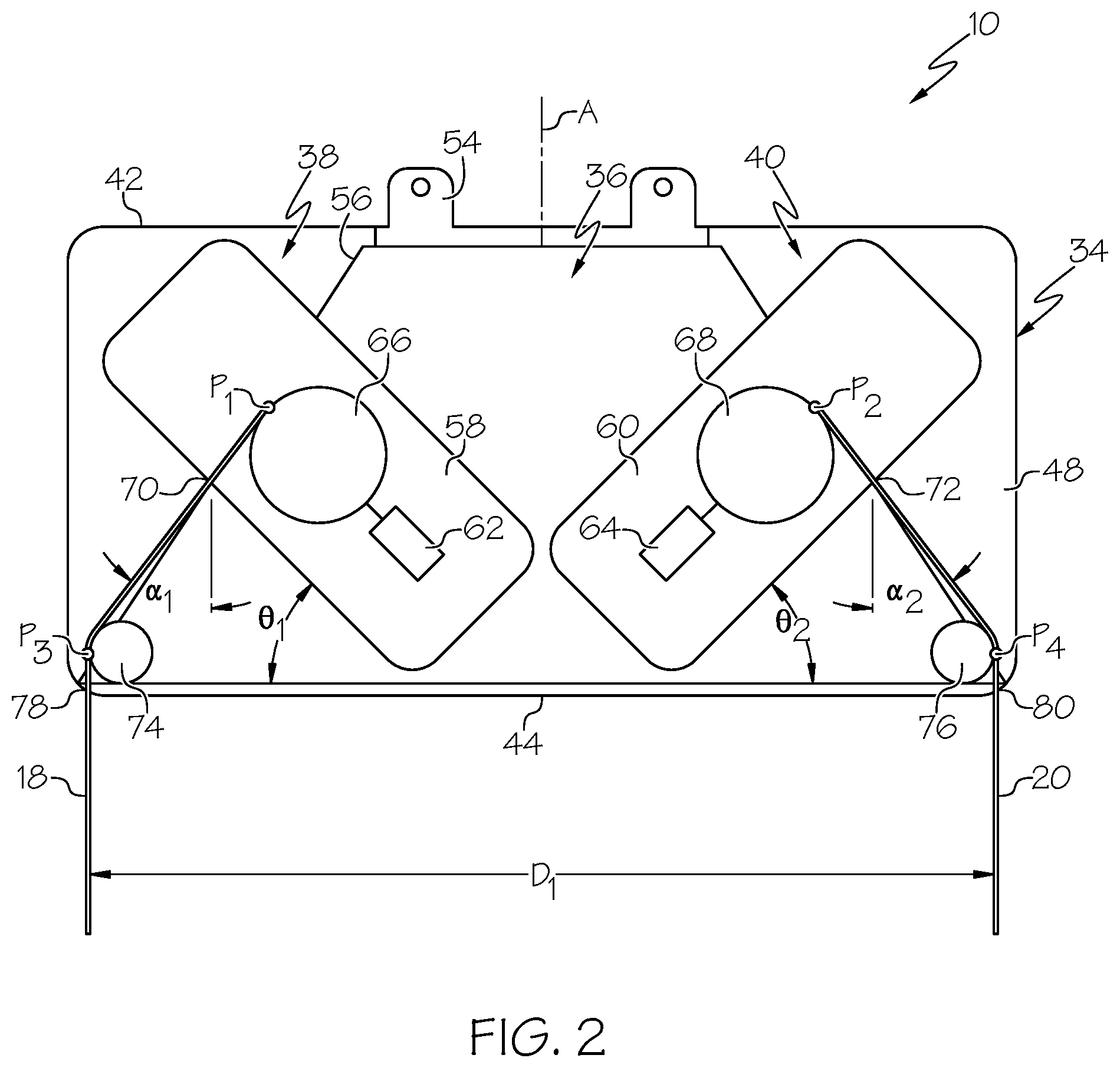
[0028] FIG. 2 is a schematic view of the overhead person lifting apparatus of FIG. 1, according to one or more embodiments shown and described herein;
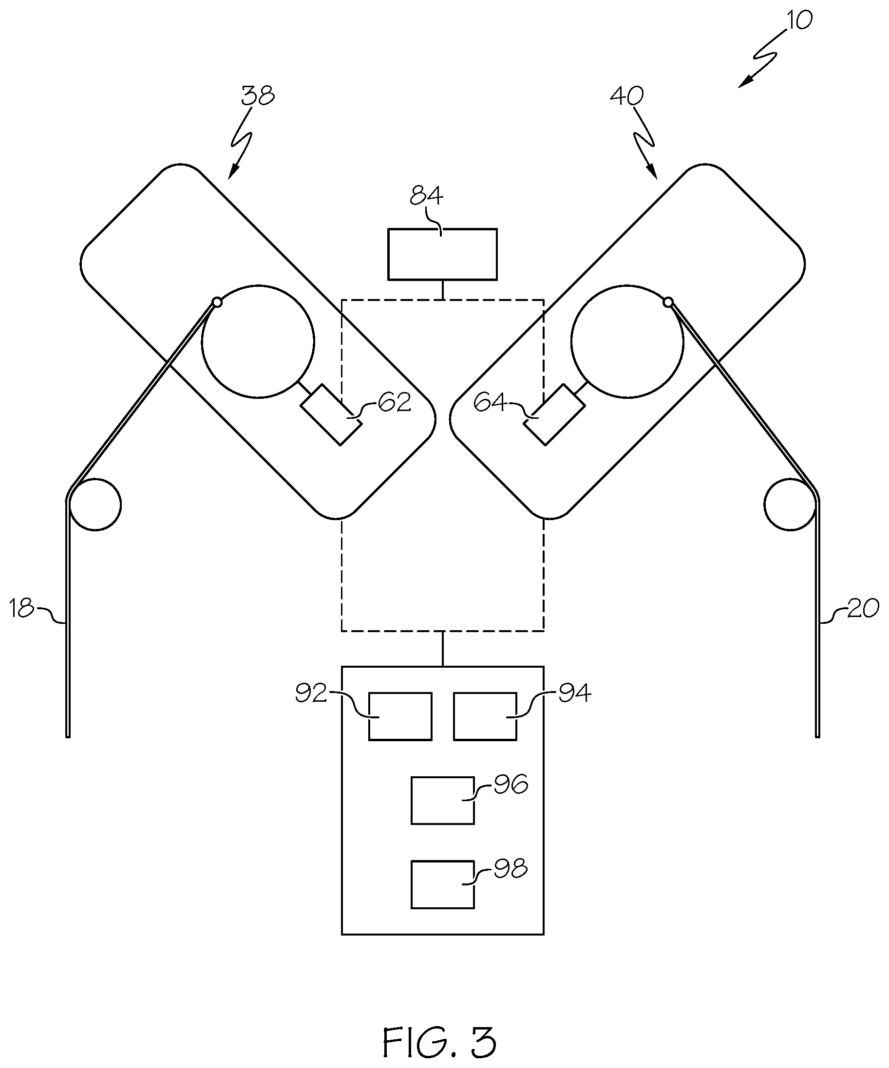
[0029] FIG. 3 is another schematic view of the overhead person lifting apparatus of FIG. 1, according to one or more embodiments shown and described herein;
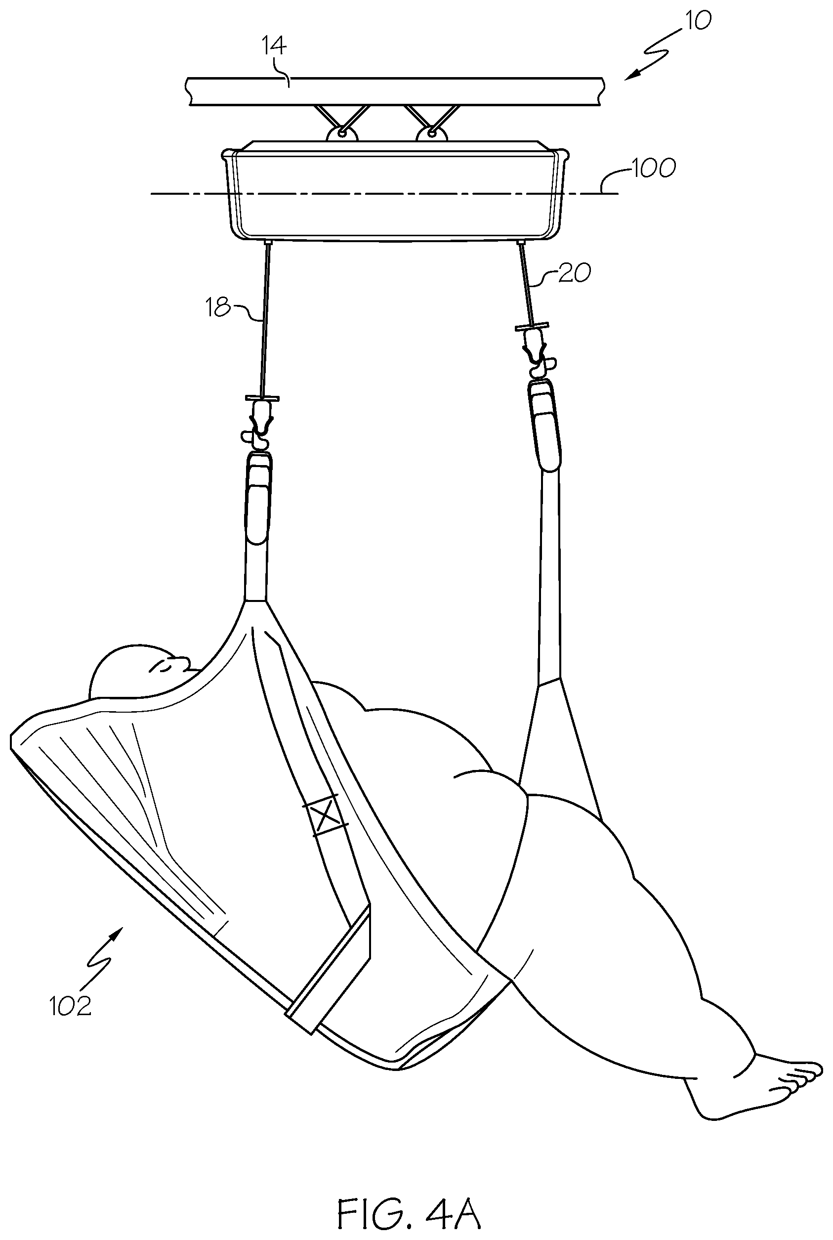
[0030] FIG. 4A is a side view of the overhead lifting apparatus of FIG. 1 in use, according to one or more embodiments shown and described herein;
[0031] FIG. 4B is a front view of a sling bar device for use with the overhead lifting apparatus of FIG. 4A, according to one or more embodiments shown and described herein;
[0032] FIG. 5 is an exemplary plot of current load versus time for a lifting event, according to one or more embodiments shown and described herein;
[0033] FIG. 6 is another exemplary plot of current load versus time for a lifting event, according to one or more embodiments shown and described herein;
[0034] FIG. 7 is another exemplary plot of current load versus time for a lifting event, according to one or more embodiments shown and described herein;
[0035] FIG. 8 is another exemplary plot of current load versus time for a lifting event, according to one or more embodiments shown and described herein;
[0036] FIG. 9 is another exemplary plot of current load versus time for a lifting event, according to one or more embodiments shown and described herein;
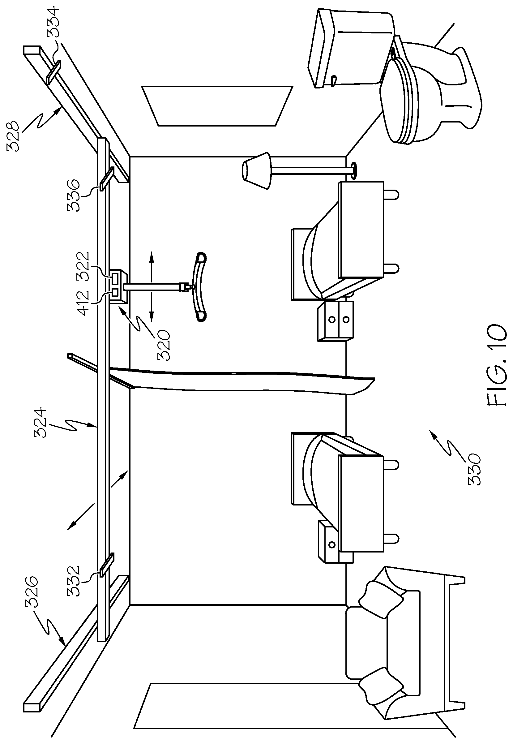
[0037] FIG. 10 illustrates a method of using a person lifting system, according to one or more embodiments shown and described herein;
[0038] FIG. 11 illustrates a plot of weight versus time along with superimposed plots of acceleration and current load, according to one or more embodiments shown and described herein;
[0039] FIG. 12 is a diagram of a person lifting system, according to one or more embodiments shown and described herein;
[0040] FIG. 13 is an exemplary plot of lifting strap length versus time for a lifting event, according to one or more embodiments shown and described herein;
[0041] FIG. 14 is another exemplary plot of lifting strap length versus time for a lifting event, according to one or more embodiments shown and described herein;
[0042] FIG. 15 is another exemplary plot of lifting strap length versus time for a lifting event, according to one or more embodiments shown and described herein;
[0043] FIG. 16 is an exemplary plot of load on a lifting strap versus time for a lifting event, according to one or more embodiments shown and described herein; and
[0044] FIG. 17 is another exemplary plot of load on a lifting strap versus time for a lifting event, according to one or more embodiments shown and described herein.
DETAILED DESCRIPTION
[0045] Reference will now be made in detail to embodiments of person lifting apparatuses and methods of operating the same, examples of which are illustrated in the accompanying drawings. Whenever possible, the same reference numerals will be used throughout the drawings to refer to the same or like parts. One embodiment of a person lifting apparatus is schematically depicted in FIG. 1, and is designated by the reference numeral 10. The person lifting apparatus may generally include two lift actuators operatively connected to accessory couplings via two lift straps, whereby each lift actuator raises and lowers the respective accessory coupling using the respective lift strap. The accessory couplings connect to a device, such as a sling bar device, which, in turn, can connect to a patient lift sling.
[0046] As two lift actuators and associated lift straps are used by the person lifting apparatuses, monitoring of the conditions of one of the lift actuators relative to the other of the lift actuators may be desired. For example, if one of the lift actuators is pulling much more current than the other of the lift actuators under operating conditions, an imbalance condition may be present. As will be described herein, the imbalance condition may be indicative of patient orientation as current draw can indicate load on the lift actuator due to patient position and weight distribution in a patient lift sling, as an example. As used herein, the terms "current draw" and "draw current" are used interchangeably to refer to an amount of current being provided by a power source under loading conditions. Various embodiments of person lifting apparatuses and methods for operating the same will be described herein with specific reference to the appended drawings.
[0047] Referring to FIG. 1, the person lifting apparatus 10 is part of an overhead patient lifting system 12 that includes one or more rails 14 that are secured or coupled to a support surface, such as a ceiling of a room. The person lifting apparatus 10 is movably coupled to the rail 14 by a carriage 16. In this embodiment, the person lifting apparatus 10 is configured to support and lift a patient with a pair of lifting straps 18 and 20. The lifting straps 18 and 20 may each include an accessory coupling 22 and 24 located at a free end 26 and 28 of the lifting straps 18 and 20. Sling bar devices 30 and 32 are illustrated connected to the accessory couplings 22 and 24. While sling bar devices 30 and 32 are illustrated, other accessories may be coupled to the lifting straps 18 and 20 depending on the desired lifting or other support operation. In some embodiments, a sling or harness may be coupled to both of the sling bar devices 30 and 32 to support a person for a person lifting and/or tilting operation. An emergency brake strap 33 may be provided that can be utilized to stop all operation of the person lifting apparatus 10 and hold the lifting straps 18 and 20 in their current positions.
[0048] Referring to FIG. 2, the person lifting apparatus 10 includes a housing 34 and a support structure 36 that is located in the housing 34 and supports a pair of lifting strap feeding devices 38 and 40 within the same housing 34. The lifting strap feeding devices 38 and 40 each wind up and pay out their respective lifting strap 18 and 20. The housing 34 includes a top 42, a bottom 44, sides 46, 48, a front 50 and a back 52 (FIG. 1) defining an enclosure that houses the lifting strap feeding devices 38 and 40. A hanging bracket 54 is located at the top 42 of the housing 34 and may be connected to the housing 34 and support structure 36. The hanging bracket 54 may also be part of or connected to the carriage 16 (FIG. 1) and allow for rotation of the housing 34 about a vertically oriented axis of rotation A. Rotation of the housing 34 using the carriage 16 may be effectuated manually and/or may be motorized. Manual rotation of the housing 34 may be caused, for example, by manually grasping one of the lifting straps 18 and 20 and/or the sling bar devices 30, 32 and applying a rotational force to the housing 34 by pulling the lifting straps 18 and 20 and/or the sling bar devices 30, 32. A brake or other stop mechanism may be used to inhibit rotation of the housing 34 when desired.
[0049] As can be seen in FIG. 2, the support structure 36 includes support components (represented by element 56, such as beams, brackets, fasteners, etc.) that support the lifting strap feeding devices 38 and 40. The strap feeding devices 38 and 40 generally include housings 58 and 60, lift actuators 62 and 64 (e.g., motors), and drums 66 and 68 that are rotated by the lift actuators 62 and 64 to wind up and pay out the lifting straps 18 and 20. The drums 66 and 68 may be coupled to a shaft of the lift actuators 62 and 64 and may be configured to extend and retract the lifting straps 18 and 20 as the lift actuators 62 and 64 rotate the drums 66 and 68 in response to a user providing an input to a control system via an input device. The strap feeding devices 38 and 40 are supported by the support structure 36 at angles .theta..sub.1 and .theta..sub.2 to horizontal. The support structure 36 supports the lifting strap feeding devices 38 and 40 at the angles .theta..sub.1 and .theta..sub.2 to horizontal such that lifting strap feed out locations 70 and 72 are not facing vertically or horizontally only, but also face outward at an angle to both vertical and horizontal. Such a non-horizontal and non-vertical arrangement for the lifting strap feeding devices 38 and 40 can allow the lifting strap feeding devices 38 and 40 to pay out the lifting straps 18 and 20 at angles .alpha..sub.1 and .alpha..sub.2 to vertical inside the housing 34 toward the sides 46 and 48 of the housing 34.
[0050] The lifting straps 18 and 20 may release from the drums 66 and 68 at points P.sub.1 and P.sub.2 where the lifting straps 18 and 20 are substantially tangent to their respective drum 66, 68. The lifting straps 18 and 20 are then directed over spacing rollers 74 and 76 that are spaced horizontally from the points P.sub.1 and P.sub.2 and offset horizontally from the drums 66 and 68 thereby increasing a horizontal spacing between the lifting straps 18 and 20 as they release from their drums 66 and 68 at points P.sub.1 and P.sub.1 to points P.sub.3 and P.sub.4 where they release from their spacing rollers 74 and 76. By the spacing rollers being "offset horizontally" from the drums, it is meant that a centerline of the spacing rollers is offset horizontally from a centerline of the drums. The points P.sub.3 and P.sub.4 may be spaced apart horizontally a predetermined distance D.sub.1, such as between about 10 inches and about 30 inches. The predetermined distance D.sub.1 depends on a number of factors including a maximum required distance between the free ends 26 and 28 of the lifting straps 18 and 20 under operating conditions. FIG. 2 illustrates the lifting straps 18 and 20 in a freely hanging configuration with the lifting straps 18 and 20 not in use for a lifting operation. In the freely hanging configuration, the lifting straps 18 and 20 hang from the spacing rollers 74 in a vertical orientation from the spacing rollers 74 and 76. The lifting straps 18 and 20 may extend downward from the spacing rollers 74 and 76 and exit the housing 34 at exit openings 78 and 80. While spacing rollers 74 and 76 are described, various other spacing members may be used that may or may not move or rotate.
[0051] Referring to FIG. 3, another schematic of operation of the person lifting apparatus 10 is illustrated including the lift actuators 62 and 64 and lifting straps 18 and 20 that are connected to the lift actuators 62 and 64. A controller 84 is operatively connected to the lift actuators 62 and 64 for controlling operation of the lift actuators 62 and 64, e.g., based on a user input using a user input device 90 (e.g., a remote control). The user input device 90 may be operably connected to the strap feeding devices 38 and 40 that feed the lifting straps 18 and 20, as discussed above, and/or connected to the controller 84. The user input device 90 may include tilt controls 92 and 94. As an example, the tilt control 82 may be a clockwise tilt control that, upon actuation, causes the strap feeding device 38 to wind up the lifting strap 18, while the strap feeding device 40 pays out the lifting strap 20. The tilt control 94 may be a counterclockwise tilt control that, upon actuation, causes the strap feeding device 38 to pay out the lifting strap 18, while the strap feeding device 40 winds up the lifting strap 20. In other embodiments, the tilt controls 92 and 94 may only raise and lower one of the lifting straps 18 and 20 (e.g., to move the head up and down while leaving the legs stationary). In some embodiments, the tilt controls 92 and 94 can be used to rotate a person from a supine position to a sitting position, for example.
[0052] The user input device 90 may also include up and down controls 96 and 98 that causes both strap feeding devices 38 and 40 to operate simultaneously to raise and lower the lifting straps 18 and 20 together. While the tilt controls 92, 94 and the up and down controls 96 and 98 are illustrated there may be other controls. For example, there may be individual up and down controls for each of the strap feeding devices 38 and 40. The user input device 90 may be wired or wirelessly connected to the strap feeding devices 38 and 40. The user input device 90 may control the strap feeding devices 38 and 40 directly, or controller 84 may receive input signals from the user input device 90.
[0053] The user input device 90 may be dedicated to controlling the strap feeding devices 38 and 40, such as a remote. In some embodiments, the user input device 90 may be a personal computing device, such as a smart phone or tablet that includes software that can be used to control operation of the strap feeding devices. Further, the user input device 90 and controller 84 may be connected to the internet for remotely controlling operation of the strap feeding devices 38 and 40.
[0054] During operation of the person lifting apparatus 10, the strap feeding devices 38 and 40 may be operated such that an imbalance condition is created. An imbalance condition may be due to, for example, paying out and/or retracting one of the lifting straps 18 and 20 an amount that causes a patient to tilt toward or away from one of the lifting straps 18 and 20 more than another beyond a predetermined amount. In these instances, one of the lift actuators 38 and 40 may experience a greater load than the other of the lift actuators 38 and 40.
[0055] Assuming the mapping from current to weight is linear, weight can be quantified based on current measurements. Comparing the ratio of currents pulled by the lift actuators 38 and 40 during operation to a predetermined value can be used to determine an imbalance condition. This predetermined value can be selected through clinical evaluations and assessments of patient loading using the two lifting straps 18 and 20, in order to accommodate different patient morphologies. Any non-linearity in the current-to-weight function may be addressed in logic using, for example, a look-up table and interpolation.
[0056] In the illustrated example, the controller 84 may include circuitry that reads the current being pulled by the lift actuators 38 and 40 from a power source. In some embodiments, a current measuring device, also represented by element 84, may measure the current from the power source and provide an output to the controller 84. As an example, the predetermined value may be provided as a ratio of 1.5 that is saved in memory of the controller 84. The current measuring device may be part of the controller 84 and/or may be separate from the controller 84. Referring to the Table below, the first example illustrates a balance condition with a current ratio of 1.25, below the 1.5 predetermined value. The second example illustrates an imbalance condition with a current ratio of 1.75, above the predetermined value.
TABLE-US-00001 TABLE Imbalance Condition Strap 1 Strap 1 Strap 2 Strap 2 Current Imbalance Weight Current Weight Current Ratio Present? Example 1 400 lbs 10 A 320 lbs 8 A 1.25 No Example 2 140 lbs 3.5 A 80 lbs 2 A 1.75 Yes
[0057] The controller 84, upon determining an imbalance condition exists, may take any one of a number of actions, such as to no longer allow tilting in a direction which increases the ratio. As another example, the controller 84 may tilt the person lifting apparatus 10 automatically in a direction that reduces the ratio. In some embodiments, there may be a scale of predetermined values and the action performed by the controller 84 may depend on the magnitude of the imbalance. Since the controller 84 can continually monitor the current ratio, a ratio of 1.75 may be unlikely. However, such a condition may be present, for example, when a support is suddenly removed. While the predetermined value described above is greater than 1, the predetermined value may below 1, such as 0.5 or below, depending on how the calculation is made. The controller 84 may further provide an indication to a user that an imbalance condition is present (e.g., visual and/or audible).
[0058] Referring to FIG. 4A, the person lifting apparatus 10 is illustrated with its long axis 100 parallel with a direction of travel along the rail 14. A sling 102 is illustrated connected to the sling bar devices 30 and 32. As shown in FIG. 4B, the sling bar devices 30, 32 (only sling bar device 30 is shown) includes a connector 104 for coupling the sling bar device 30 to the person lifting apparatus 10. The connector 104 is fixedly coupled to the sling bar device 30 in FIG. 4B, although in other embodiments, the connector 104 may be movably coupled to the sling bar device 30. Allowing the connector 104 to move with respect to the sling bar device 30 may help to decrease the torque forces on the connector 104 when the sling 102 is coupled to the sling bar device 30, maintain the alignment of the sling 102, sling bar device 30, and person lifting apparatus 10, and prevent twisting of various components.
[0059] The sling bar device 30 includes an elongated bar 106 and two hooks 108 coupled to the distal ends of the elongated bar 106. In other embodiments, the sling bar device 30 may be an X-shaped sling bar that includes two curved frame members coupled by a middle frame member and including four support apparatus coupling mechanisms. In still other embodiments, the sling bar may include a U-shaped frame including two support apparatus coupling mechanisms and a U-shaped handle extending from the frame to provide stability to a subject being lifted. Other sling bar configurations are contemplated. Various sling bar configurations are described in greater detail in U.S. Pat. No. 9,757,297, entitled "Person Lift System."
[0060] The hooks 108 include a coupling base 110 with a recessed space 112 therein and a latch 114 configured to selectively enclose the recessed space 112. The latch 114 is pivotally coupled to the coupling base 110 and is configured to extend across the recessed space 112 in a closed position and rotate towards the recessed space 112 in an open position. In operation, when a user couples the sling 102 to the hook 108, the user lifts the latch 114 (i.e., rotates the latch 114 away from the recessed space 112), to allow the strap(s) or other portion of the sling 102 to be inserted into the recessed space 112. When a user removes the sling 102 from the hook 108, the user lifts the latch 114 to rotate the latch 114 toward an open position (i.e., rotates the latch 114 away from the recessed space 112) such as with a sling strap to allow the sling 102 to be removed from the recessed space 112.
[0061] Suitable sling bars include, by way of example and not limitation, those commercially available under the trade name SlingGuard from Liko, HILL-ROM.RTM., or Hill-Rom Services, Inc. (Batesville, Ind.). Additionally, it is contemplated that some embodiments may not include a sling bar.
[0062] Current load being pulled by an actuator, whether a single actuator or multiple actuators as described above, can be used to determine a type of lifting event (e.g., transfer, reposition, etc.) that is occurring in real time, or has occurred in the past using changes in load data. FIG. 5 illustrates an example of a filtered current load over time for a lifting event using a person lifting apparatus from a patient sitting in a chair to the patient lying in a bed. In this example, a single actuator for a single strap person lifting apparatus is illustrated. The plot 200 for the current load generally has a raising portion 202, a repositioning portion 204 and a lowering portion 206. In this regard, there are three distinct events--raising, repositioning and lowering--that can be identified by the shape of the plot 200.
[0063] Upon activation of the actuator, the current load on the actuator increases in section 208 before any lifting of the patient. This rise in current load is due merely to activation of the actuator. In section 210, the actuator remains unloaded for a period of time as slack is let out of the lifting strap connected to the actuator. Other actions can result in this section 210 having a relatively flat current load, such as inactivity or delay in use of the actuator since time passes with no increase in current load. The current load on the actuator increases in section 212 as the patient begins being lifted from the chair and an increasing amount of weight of the patient is transferred from the chair to the actuator. Because the chair may be relatively hard compared to a bed, for example, the slope of the increase in section 212 may be expected to be steeper than a slope seen for other softer objects such as a bed, which will be described below. At section 214, the actuator is fully loaded as the patient is removed from/unsupported by the chair and lifted to a desired height.
[0064] Once at the desired height, the actuator may be deactivated and the lifting strap locked at the desired height for repositioning the patient at section 216. The repositioning step may be accomplished using the person lifting apparatus to move the patient from the chair to a bed. With the patient in the desired position, the actuator may again be activated, which causes a jump in current load at section 218. Because the patient is being lowered in the lowering portion 206, the current draw by the actuator is generally less in the lowering portion 206 than in the raising portion 202. At section 220, the patient is held unsupported by the bed. At section 222, the current load increases as the patient is lowered onto the bed. Section 224 shows the actuator load being relatively constant for a period of time until the actuator is deactivated.
[0065] A computing device (such as in communication with controller 84) may include memory having logic that, when executed by a processor, identifies the raising portion 202, repositioning portion 204 and lowering portion 206, the sections 210, 212, 214, 216, 218, 220, 222, 224 and/or certain points of interest therein. For example, one identification point 226 may be the beginning of section 212 when the current load rises above the current load in unloaded section 210. Another identification point 228 may be the end of section 212 when the current load begins to plateau indicating the patient being fully supported. A slope of a line passing through the identification points 226 and 228 may provide information regarding a type of object (e.g., hard or soft) the patient is being lifted from, as mentioned above. For example, without wishing to be bound by theory, one might expect steeper slopes for harder objects (e.g., chairs) than softer objects (e.g., beds). Other identification points 230 and 232 may be the beginning and end of section 216, which can provide information regarding how long a repositioning event took place. Unusually long or short repositioning events may indicate a need to look more closely into those events. Other identification points 234 and 236 may include the beginning and end of section 222. There may be other points of interest depending, for example, on the type of lifting event. For example, identification points may be determined based on the characteristics of a specific lifting event. Of course, how a patient is handled and supported by an operator of the patient lifting apparatus during a lifting process may affect the current versus time plot characteristics.
[0066] Referring to FIG. 6, an example of a filtered current load versus time plot for another lifting event using the person lifting apparatus for a patient lying in bed and being transferred to a chair is illustrated. In this example, only a raising portion 240 and a repositioning portion 242 are shown. Similar to FIG. 5, upon activation of the actuator, the current load on the actuator increases in section 244 before any lifting of the patient. This rise in current load is due merely to activation of the actuator. In section 246, the actuator remains unloaded for a period of time as slack is let out of the lifting strap connected to the actuator. The current load on the actuator increases in section 248 as the patient begins being lifted from the bed and an increasing amount of weight of the patient is transferred from the chair to the actuator. Because the bed may be relatively soft compared to a chair, the slope S of the increase in section 248 may be expected to be less steep than a slope seen for other hard objects such as a chair. At section 250, the actuator is fully loaded as the patient is removed from/unsupported by the bed and lifted to a desired height.
[0067] Once at the desired height, the actuator may be deactivated and the lifting strap locked at the desired height for repositioning the patient at section 252. The repositioning step may be accomplished using the person lifting apparatus to move the patient from the chair to a bed. With the patient in the desired position, the actuator may again be activated, which causes a jump in current load at section 254 and the lowering process begins (not shown).
[0068] FIG. 7 illustrates another example of a filtered current load versus time plot for another lifting event using the person lifting apparatus for a patient lying in bed, being repositioned and then transferred to another bed. In this example, only a raising portion 260 and a repositioning portion 262 are shown. Similar to FIGS. 5 and 6, upon activation of the actuator, the current load on the actuator increases in section 264 before any lifting of the patient. In section 266, the actuator remains unloaded for a period of time as slack is let out of the lifting strap connected to the actuator. The current load on the actuator increases in section 268 as the patient begins being lifted from the bed and an increasing amount of weight of the patient is transferred from the chair to the actuator. Because the bed may be relatively soft compared to a chair, the slope of the increase in section 268 may be expected to be less steep than a slope seen for other hard objects such as a chair.
[0069] Unlike the plot of FIG. 6, FIG. 7 illustrates a repositioning event during the lifting of the patient at identification point 270. The repositioning event divides section 268 into two subsections 268a and 268b where the slope S.sub.1 and S.sub.2 changes between the subsections 268a and 268b due to the repositioning of the patient. For example, the patient may be moved from a supine to a seated position or vice versa). This identification point 270 can allow identification of a repositioning event during patient lifting. At section 272, the actuator is fully loaded as the patient is removed from/unsupported by the bed and lifted to a desired height.
[0070] Again, once at the desired height, the actuator may be deactivated and the lifting strap locked at the desired height for repositioning the patient at section 274 The repositioning step may be accomplished using the person lifting apparatus to move the patient from one bed to another bed. Because the patient is being moved between beds, the transfer/repositioning time may be expected to be less than from a bed to a chair or chair to a bed. With the patient in the desired position, the actuator may again be activated, which causes a jump in current load at section 276 and the lowering process begins (not shown).
[0071] FIG. 8 illustrates another example of a filtered current load versus time plot for another lifting event using the person lifting apparatus for a patient lying in bed and being repositioned for a same bed. In this example, only a raising portion 280 and a repositioning portion 282 are shown. Similar to FIGS. 5-7, upon activation of the actuator, the current load on the actuator increases in section 284 before any lifting of the patient. In section 286, the actuator remains unloaded for a period of time as slack is let out of the lifting strap connected to the actuator. The current load on the actuator increases in section 288 as the patient begins being lifted from the bed and an increasing amount of weight of the patient is transferred from the chair to the actuator. Because the bed may be relatively soft compared to a chair, the slope of the increase in section 288 may be expected to be less steep than a slope seen for other hard objects such as a chair.
[0072] Like FIG. 7, FIG. 8 illustrates a repositioning event during the lifting of the patient at identification point 290. The repositioning event divides section 288 into two subsections 288a and 288b where the slope S.sub.1 and S.sub.2 changes between the subsections 288a and 288b due to the repositioning of the patient. At section 292, the actuator is fully loaded as the patient is removed from/unsupported by the bed and lifted to a desired height. Because the patient is not being transferred far, section 292 may be relatively short in duration as the patient may not need lifted very far off of the bed.
[0073] Again, once at the desired height, the actuator may be deactivated and the lifting strap locked at the desired height for repositioning the patient at section 294. The repositioning step may be accomplished using the person lifting apparatus to move the patient from one location in the bed to another location in the same bed. Because the patient is being moved on the same bed, the transfer/repositioning time may be expected to be less than, for example, from a bed to a chair or chair to a bed. With the patient in the desired position, the actuator may again be activated, which causes a jump in current load at section 296 and the lowering process begins (not shown).
[0074] FIG. 9 illustrates another example of a filtered current load versus time plot for another lifting event using the person lifting apparatus for a patient being lifted from a floor, such as a floor rescue. Only a raising portion 300 and a repositioning portion 302 are shown. Upon activation of the actuator, the current load on the actuator increases in section 304 before any lifting of the patient. In section 306, the actuator remains unloaded for a period of time as slack is let out of the lifting strap connected to the actuator. The current load on the actuator increases in section 308 as the patient begins being lifted from the bed and an increasing amount of weight of the patient is transferred from the chair to the actuator.
[0075] At section 310, the actuator is fully loaded as the patient is removed from/unsupported by the floor and lifted to a desired height. Because the patient is being lifted from the floor, one would expect section 310 to be relatively long in duration compared to lifting from a chair or a bed. This length of time of section 310 can be used to identify a possible floor rescue.
[0076] While current load on the actuator is described primarily above, other sensors can be used to identify a lifting event. Referring to FIG. 10, in addition to monitoring current, a person lifting apparatus 320 may include a motion sensor 322, such as an accelerometer, and a weight sensor 412 that can be used to monitor motion of the person lifting apparatus 320. For example, it may be expected that a higher level of vibration may be expected with the traverse rail 324 and person lifting apparatus 320 moving along end rails 326 and 328 compared to the person lifting apparatus 320 moving along the traverse rail 324 alone. This detection can give information of how the patient is being moved around within a room 330 (e.g., side-to-side or front-to-back). Further, proximity sensors 332, 334 and 336 may be used for additional information. For example, if sensors 332 and 334 are activated, the patient was likely moved to a bedside chair 338 using the person lifting apparatus. If sensors 334 and 336 are activated, the patient was likely moved to a toilet using the person lifting apparatus 320. As indicated above, it can also be determined whether the patient has been lifted, transferred and lowered using the current loads on the actuator of the person lifting apparatus 320.
[0077] Referring to FIG. 11, a weight curve 350 indicative of weight on the lifting strap provided by the weight sensor 412, an acceleration curve 352 indicative of acceleration (vibration) of the person lifting apparatus 320 and a current load curve 354 indicative of current load being pulled by the actuator are illustrated superimposed on one another versus time. FIG. 11 illustrates how the curves 350, 352 and 354 can interplay to provide a more complete picture of a particular lifting event. Looking at the weight curve 350, for example, in section 356, the patient is being lifted above a bed to a predetermined height at section 358. The corresponding section of the current load curve 354 shows a shallow slope which can indicate lifting from a soft surface such as a bed. At section 360, legs of the patient are rotated to a side while being manually supported thereby reducing the weight on the lifting strap. At section 362, the patient is held at the predetermined height while being transferred (e.g., pushed) to a chair. The corresponding section of the acceleration curve shows increased vibration which can indicate lateral movement of the person lifting apparatus 320. At section 364, the patient is being lowered while being increasingly supported by the chair. The corresponding section of the current load curve 354 shows a steeper slope which can indicate lowering onto a harder surface such as a chair.
[0078] Referring to FIG. 12, an exemplary person lifting system 400 utilizing the person lifting apparatus 320 is illustrated schematically. The person lifting system 400 includes a communication path 402, a processor 404, a memory module 406, the proximity sensors 332, 334 and 336 and the person lifting apparatus 320. The person lifting apparatus 320 can include its own processor 410 that can be used to detect current load as a current measuring device, motion sensor 322 and weight sensor 412 (e.g., a scale). As will be discussed below, the person lifting apparatus 320 may further include a position sensor 420 (e.g., a potentiometer) that can be used to detect a position of lifting strap 422. For example, the position sensor 420 may be used to determine a paid out length of the lifting strap from a stowed or other set position. The weight information provided by the weight sensor 412 and the position information provided by the position sensor 420 can be used to determine whether a lifting event is occurring and a type of lifting event.
[0079] The processor 404, 410 may include any device capable of executing machine-readable instructions stored on a non-transitory computer-readable medium. The processor 404, 410 may include one or more processors. Accordingly, each processor 404, 410 may include a controller, an integrated circuit, a microchip, a computer, and/or any other computing device. The person lifting system 400 may further include network interface hardware 408. The communication path 402 can provide data interconnectivity between the various modules that may send and receive data. The communication path 402 may be wired and/or wireless.
[0080] The person lifting system 400 may further include the network interface hardware 408 for communicatively coupling the person lifting system 400 with a network 413. The network interface hardware 408 can be communicatively coupled to the communication path 402 and can be any device capable to transmitting and receiving data via the network 413. The network interface hardware 408 may include antenna, modem, LAN port, Wi-Fi, mobile communications hardware, etc. The network interface hardware 408 may include a Bluetooth.RTM. module for sending and receiving Bluetooth communications to and from a mobile device 414.
[0081] Referring now to FIG. 13, an exemplary plot 440 of lifting strap position over time is illustrated for a lifting event from a bed to a chair. The plot 440 for the lifting strap position generally has a raising portion 442, a repositioning portion 444 and a lowering portion 446. As above with current load, there are three distinct events--raising, repositioning and lowering--that can be identified by the shape of the plot 440.
[0082] Upon lowering of the lifting strap, a length of the lifting strap increases in section 448, as detected by the position sensor. In some embodiments, for example, the lifting strap may be lowered from an initial, stowed position at t=0. At section 450, the length of the lifting strap may remain constant for a period of time due to connecting the lifting strap to another device, such as a sling or repositioning sheet. After connecting the lifting strap, the lifting strap may begin to be raised at point 452. At section 454 the lifting strap is raised until fully loaded at point 454. At point 456, the length of the lifting strap remains constant as the patient is transferred from the bed to the chair. Once the patient is positioned over the chair, the lifting strap is again lowered at point 458. At section 460, the lifting strap is lowered until the patient is at least partially supported by the chair at point 462. At point 464, the length of the lifting strap remains constant in section 466 as the lifting strap is disconnected from the device. At section 468, the lifting strap is again raised unloaded to its initial, stowed position.
[0083] As may be appreciated, the raising portion 442 indicated a maximum strap length that is less than that of the lowering portion 446. This disparity in length between the raising portion 442 and the lowering portion 446 can indicate that the patient began on a relatively raised, initial surface (e.g., a bed) than the final surface (e.g., a chair) to which the patient was repositioned. Compare plot 470 of FIG. 14 where a raising portion 472 is about a same length as a lowering portion 476 after a repositioning portion 478. This substantially equivalent length of the lifting strap can indicate a repositioning on a same surface, such as a repositioning process of sitting up in a bed from a supine position.
[0084] Referring to FIG. 14, upon lowering of the lifting strap, a length of the lifting strap increases in section 480, as detected by the position sensor. At section 482, the length of the lifting strap may remain constant for a period of time due to connecting the lifting strap to another device, such as a sling or repositioning sheet. After connecting the lifting strap, the lifting strap may begin to be raised at point 484. At section 486 the lifting strap is raised until fully loaded at point 488. At point 490, the length of the lifting strap remains constant as the patient is transferred from the bed to the chair. In this example, the fully loaded point 488 is relatively near the repositioning point 490 compared to the example of FIG. 13. This may be because a particular repositioning event may not require much lifting above the surface, such as a repositioning in a bed. Once the patient is repositioned, the lifting strap is again lowered at point 492. At section 494, the lifting strap is lowered until the patient is at least partially supported by the surface at point 496. At point 498, the length of the lifting strap remains constant in section 500 as the lifting strap is disconnected from the device. At section 502, the lifting strap is again raised unloaded to its initial, stowed position.
[0085] FIG. 15 illustrates a variety of variables that can be useful in determining whether a lifting event is occurring and what type of lifting event, such as a transfer from one surface to another or a reposition on a single surface. The variables may be defined as follows:
[0086] LUP.sub.start, LUP.sub.end: Lowest unloaded position (strap connection and disconnection positions. LUP is influenced by height of the transfer surface. A longer extension could indicate a lower surface (e.g., a chair), while a higher surface could mean a bed or stretcher, as examples.
[0087] .DELTA.LUP: Difference between the lowest unloaded positions (LUP.sub.start-LUP.sub.end). .DELTA.LUP is influenced be different heights between surfaces. A low .DELTA.LUP may indicate a reposition in a bed or transfer from a bed to a stretcher. A higher .DELTA.LUP suggests bed to chair transfer or similar transfer.
[0088] LLP.sub.lifting, LLP.sub.lowering: Lowest position at full load (just after patient is fully lifted or just before patient begins offloading). LLP may be higher if there is a need for increased patient elevation, for example, to clear a side rail or arm rest, which may indicate an increased likelihood of a bed to chair transfer.
[0089] .DELTA.LLP: Difference between the lowest loaded positions (LLP.sub.lifting-LLP.sub.lowering). Note that LUP and LLP could be defined relative to stow height or transfer height. Like .DELTA.LUP, .DELTA.LLP is influenced by different heights between two surfaces and also barriers between the surfaces.
[0090] .DELTA.Slack.sub.lifting, .DELTA.Slack.sub.lowering: Difference between the lowest unloaded position and lowest position at full load (LUP.sub.start-LLP.sub.lifting) or (LUP.sub.end-LLP.sub.lowering). .DELTA.Slack is influenced by the type of sling used. For example, a repositioning sheet appears to require more slack to connect loops (and therefore more travel during loading) than a seated sling.
[0091] .DELTA.Tuat.sub.lowering, .DELTA.Tuat.sub.lifting: Difference between the lowest loaded position (LLP) and the transfer height. .DELTA.Taut is similar to .DELTA.LLP.
[0092] t.sub.prepare: Time to connect lifting straps and prepare patient. t.sub.prepare can be highly patient dependent. Extra time may be needed to prepare to lift some patients and longer t.sub.prepare may indicate that a sling is being used (e.g., a repositioning sheet may take longer to connect than other devices).
[0093] t.sub.transfer: Time of highest static position while fully loaded (i.e., transfer time). t.sub.transfer is influenced by the type of movement. For example, a repositioning in bed may require less time than a seated transfer.
[0094] As mentioned above, weight information from a weight sensor can also be used to determine characteristics of a repositioning event. FIG. 16, as an example, is representative of a transfer event using a seated sling (e.g., from bed to chair) and FIG. 17, as another example, is representative of a repositioning event using a repositioning sling (e.g., in a bed). Comparing the plots 510 and 512, an average slope of the plot 512 using the repositioning sling indicates a more gradual increase in load when lifting compared to the plot 510 of the seated sling. The plot 512 also shows a more rounded curve near a beginning and an end of the plot 512. The seated sling is more likely to shift and slip during loading creating an irregular shape of the plot 510 compared to the relatively smooth curve of the plot 512 of the repositioning sling. For example a bump 514 appears in a loading section of the plot 510, which may be caused by the patient's back lifting off of the bed followed by the posterior. Load variations may be caused by the patient dragging on the bed if not fully lifted, such as when transferring with a repositioning sheet. Discontinuities could be caused by recognizable events, such as feet leaving the bed or the caregiver lifting the feet or other body part during a transfer or reposition event.
[0095] Additional sensors may be used to increase accuracy of type of lifting event that is occurring or has occurred. For example, sensors that measure lateral displacement of the person lifting apparatus can improve accuracy in determining details of a lifting operation. For example, a sensor providing lateral displacement information can be used to determine a transfer operation as a function of distance rather than as a function of time alone. For example, a caregiver could transfer a patient laterally while lifting/lowering the patient. In this example, using the sensor that provides lateral displacement information may increase chances for accuracy in identifying the transfer event. Lateral displacement may be measured in a number of ways, such as using a Hall-effect sensor, a non-contact ultrasonic sensor and/or a non-contact linear/rotary variable differential transformer (LDVT or RVDT).
[0096] The above-described person lifting systems utilize person lifting apparatuses and can detect whether a lifting event has occurred. In some embodiments, the person lifting systems can use identification points to determine a type of lifting event that has occurred. The information can be monitored locally or remotely using computing devices.
[0097] It will be apparent to those skilled in the art that various modifications and variations can be made to the embodiments described herein without departing from the spirit and scope of the claimed subject matter. Thus it is intended that the specification cover the modifications and variations of the various embodiments described herein provided such modification and variations come within the scope of the appended claims and their equivalents.
* * * * *
D00000
D00001
D00002
D00003
D00004
D00005
D00006
D00007
D00008
D00009
D00010
D00011
D00012

D00013

D00014

XML
uspto.report is an independent third-party trademark research tool that is not affiliated, endorsed, or sponsored by the United States Patent and Trademark Office (USPTO) or any other governmental organization. The information provided by uspto.report is based on publicly available data at the time of writing and is intended for informational purposes only.
While we strive to provide accurate and up-to-date information, we do not guarantee the accuracy, completeness, reliability, or suitability of the information displayed on this site. The use of this site is at your own risk. Any reliance you place on such information is therefore strictly at your own risk.
All official trademark data, including owner information, should be verified by visiting the official USPTO website at www.uspto.gov. This site is not intended to replace professional legal advice and should not be used as a substitute for consulting with a legal professional who is knowledgeable about trademark law.