Wearable Device Capable Of Blood Pressure Measurement
LIN; Shiming
U.S. patent application number 16/465504 was filed with the patent office on 2020-03-19 for wearable device capable of blood pressure measurement. The applicant listed for this patent is BIV MEDICAL, LTD., Shiming LIN. Invention is credited to Shiming LIN.
| Application Number | 20200085319 16/465504 |
| Document ID | / |
| Family ID | 62241240 |
| Filed Date | 2020-03-19 |


| United States Patent Application | 20200085319 |
| Kind Code | A1 |
| LIN; Shiming | March 19, 2020 |
WEARABLE DEVICE CAPABLE OF BLOOD PRESSURE MEASUREMENT
Abstract
The present invention provides a wearable device capable of blood pressure measurement, comprising a wrist band assembly, a display unit provided on the wrist band assembly, and a detachable bladder provided on a backside of the wrist band assembly, wherein the wrist band assembly is provided with a micro air pump connected to the detachable bladder, an air pressure sensor provided on a side of the detachable bladder, and a processor connected to the micro air pump and the air pressure sensor, and the processor activates the micro air pump according to a trigger signal in order for the micro air pump to inflate the detachable bladder and for a user's blood pressure parameters to be derived from data sent by the air pressure sensor to the processor.
| Inventors: | LIN; Shiming; (Taipei, TW) | ||||||||||
| Applicant: |
|
||||||||||
|---|---|---|---|---|---|---|---|---|---|---|---|
| Family ID: | 62241240 | ||||||||||
| Appl. No.: | 16/465504 | ||||||||||
| Filed: | November 29, 2017 | ||||||||||
| PCT Filed: | November 29, 2017 | ||||||||||
| PCT NO: | PCT/CN2017/113531 | ||||||||||
| 371 Date: | May 30, 2019 |
Related U.S. Patent Documents
| Application Number | Filing Date | Patent Number | ||
|---|---|---|---|---|
| 62497740 | Dec 1, 2016 | |||
| 62497747 | Dec 1, 2016 | |||
| 62601843 | Apr 4, 2017 | |||
| Current U.S. Class: | 1/1 |
| Current CPC Class: | F04B 43/02 20130101; F04B 39/123 20130101; A61B 5/02141 20130101; A61B 5/046 20130101; A61B 5/0225 20130101; A61B 5/0235 20130101; F04B 53/10 20130101; A61B 5/02 20130101; F04B 45/047 20130101; A61B 5/02208 20130101; A61B 5/021 20130101; A61B 5/681 20130101; F04B 39/121 20130101 |
| International Class: | A61B 5/0225 20060101 A61B005/0225; A61B 5/021 20060101 A61B005/021; A61B 5/00 20060101 A61B005/00; F04B 43/02 20060101 F04B043/02; F04B 53/10 20060101 F04B053/10 |
Claims
1. A wearable device capable of blood pressure measurement, comprising a wrist band assembly, a display unit provided on the wrist band assembly, and a detachable bladder provided on a backside of the wrist band assembly, wherein the wrist band assembly is provided with a micro air pump connected to the detachable bladder, an air pressure sensor provided on a side of the detachable bladder, and a processor connected to the micro air pump and the air pressure sensor, and the processor activates the micro air pump according to a trigger signal in order for the micro air pump to inflate the detachable bladder and for a user's blood pressure parameters to be derived from data sent by the air pressure sensor to the processor.
2. The wearable device of claim 1, wherein the wrist band assembly includes a watch case and a wrist band coupled to the watch case; and the detachable bladder is not coupled to the wrist band but is connected to the backside of the watch case by a detachable means.
3. The wearable device of claim 2, wherein the detachable bladder includes a hollow bladder body, two bladder wings that extend from the hollow bladder body in two opposite lateral directions respectively, an air delivery hole, and an air pressure detection hole, the latter two of which are provided at the hollow bladder body in such a way that an imaginary line connecting the two holes is parallel/perpendicular to the wrist band.
4. The wearable device of claim 3, wherein the bilateral bladder wings of the detachable bladder are each provided with an arcuate supporting plate.
5. The wearable device of claim 4, wherein the arcuate supporting plates are integrally formed with the bilateral bladder wings of the detachable bladder.
6. The wearable device of claim 3, wherein the watch case is provided therein with a connecting tube, the connecting tube has one end connected to the air outlet of the micro air pump and the opposite end connected to the first tubular base of the watch case, and the first tubular base is configured to be inserted by the airtight annular post at the air delivery hole of the hollow bladder body so that the air in the micro air pump can be guided into and thereby inflate the detachable bladder.
7. The wearable device of claim 6, wherein the watch case is provided therein with a branch tube in communication with the connecting tube and a pressure relief valve provided at one end of the branch tube; and, the processor is connected to the pressure relief valve and is configured to trigger and thereby open the pressure relief valve according to another trigger signal, in order to guide the air in the hollow bladder body through the branch tube and the pressure relief valve to a pressure relief hole at the other side of the pressure relief valve.
8. The wearable device of claim 3, wherein the watch case is provided with a second tubular base, the air pressure sensor has a probe fixedly placed in the second tubular base, and the probe is inserted into an airtight annular post at an air pressure detection hole of the hollow bladder body in order for the air pressure sensor on the second tubular base to detect air pressure parameters in the hollow bladder body.
9. The wearable device of claim 3, wherein the bilaterally extending bladder wings of the detachable bladder extend along the wrist band.
10. The wearable device of claim 9, wherein the total length of the detachable bladder is equal to 0.5 to 0.8 times the circumference of the wrist band.
11. The wearable device of claim 9, wherein the width of the detachable bladder is equal to 0.4 to 0.6 times the length of the detachable bladder.
Description
BACKGROUND OF THE INVENTION
1. Technical Field
[0001] The present invention relates to a wearable device and more particularly to a wearable device having a blood pressure measuring function.
2. Description of Related Art
[0002] 24-hour ambulatory blood pressure monitoring at a fixed time interval contributes significantly to the prevention of hypertension. By measuring a person's blood pressure ambulatorily at regular intervals, errors that sporadic incidents (e.g., an outburst of emotion, drinking, eating, or smoking) may cause to the person's blood pressure measurements can be recorded in real time to facilitate tracking. More importantly, an analysis of the data obtained by monitoring a patient's blood pressure ambulatorily on a regular basis helps reveal the patient's health condition and determine in advance whether the patient is prone to hypertension or prehypertension.
[0003] The conventional sphygmomanometer cuffs include a strap and a bladder in the strap and are used in the following manner. To begin with, the strap is wrapped around a person's upper arm, and air is pumped into the bladder to compress, and eventually occlude, the brachial artery in the upper arm. Then, the compression is gradually released, and blood flow in the artery resumes intermittently as the heart keeps throbbing. During the pressurizing and depressurizing process of the cuff, blood pressure in the compressed artery is transmitted to the cuff, and fluctuations of the cuff pressure (i.e., pressure pulses) reflect vibrations of the artery wall (which result from pulsation of the heart). Blood pressure values, therefore, can be determined by measuring the amplitudes of the pressure in the cuff. However, the conventional sphygmomanometer cuffs are not suitable as a daily wearable item because they must be tied around the upper arm. Moreover, the conventional sphygmomanometer cuffs, which are wrapped directly around the upper arm, tend to discomfort their users while being inflated to occlude the blood flow in the upper arm.
BRIEF SUMMARY OF THE INVENTION
[0004] One objective of the present invention is to provide a wearable device that not only can measure a user's blood pressure in an ambulatory manner, but also serves as a daily wearable item.
[0005] In order to achieve the above objective, the present invention provides a wearable device capable of blood pressure measurement, comprising a wrist band assembly, a display unit provided on the wrist band assembly, and a detachable bladder provided on a backside of the wrist band assembly, wherein the wrist band assembly is provided with a micro air pump connected to the detachable bladder, an air pressure sensor provided on a side of the detachable bladder, and a processor connected to the micro air pump and the air pressure sensor, and the processor activates the micro air pump according to a trigger signal in order for the micro air pump to inflate the detachable bladder and for a user's blood pressure parameters to be derived from data sent by the air pressure sensor to the processor.
[0006] Furthermore, the wrist band assembly includes a watch case and a wrist band coupled to the watch case. The detachable bladder is not coupled to the wrist band but is connected to the backside of the watch case by a detachable means.
[0007] Furthermore, the detachable bladder includes a hollow bladder body, two bladder wings that extend from the hollow bladder body in two opposite lateral directions respectively, an air delivery hole, and an air pressure detection hole, the latter two of which are provided at the hollow bladder body in such a way that an imaginary line connecting the two holes is parallel/perpendicular to the wrist band.
[0008] Furthermore, the bilateral bladder wings of the detachable bladder are each provided with an arcuate supporting plate.
[0009] Furthermore, the arcuate supporting plates are integrally formed with the bilateral bladder wings of the detachable bladder.
[0010] Furthermore, the watch case is provided therein with a connecting tube. The connecting tube has one end connected to the air outlet of the micro air pump and the opposite end connected to the first tubular base of the watch case. The first tubular base is configured to be inserted by the airtight annular post at the air delivery hole of the hollow bladder body so that the air in the micro air pump can be guided into and thereby inflate the detachable bladder.
[0011] Furthermore, the watch case is provided therein with a branch tube in communication with the connecting tube and a pressure relief valve provided at one end of the branch tube. The processor is connected to the pressure relief valve and is configured to trigger and thereby open the pressure relief valve according to another trigger signal, in order to guide the air in the hollow bladder body through the branch tube and the pressure relief valve to a pressure relief hole at the other side of the pressure relief valve.
[0012] Furthermore, the watch case is provided with a second tubular base. The air pressure sensor has a probe fixedly placed in the second tubular base, and the probe is inserted into an airtight annular post at an air pressure detection hole of the hollow bladder body in order for the air pressure sensor on the second tubular base to detect air pressure parameters in the hollow bladder body.
[0013] Furthermore, the bilaterally extending bladder wings of the detachable bladder extend along the wrist band.
[0014] Furthermore, the total length of the detachable bladder is approximately equal to 0.5 to 0.8 times the circumference of the wrist band.
[0015] Furthermore, the width of the detachable bladder is approximately equal to 0.4 to 0.6 times the length of the detachable bladder.
[0016] Comparing to the conventional techniques, the present invention has the following advantages:
[0017] 1. The wearable device capable of blood pressure measurement according to the present invention can be put on conveniently for 24-hour ambulatory blood pressure monitoring at a fixed time interval, allowing a physician to determine whether the user has hypertension or prehypertension.
[0018] 2. The wearable device capable of blood pressure measurement according to the present invention can reduce the discomfort of blood pressure measurement and thereby provide better user experience than its prior art counterparts.
[0019] 3. The wearable device capable of blood pressure measurement according to the present invention can reduce sensing errors attributable to sweat on the skin as are typical of the conventional optical sensing methods. The wearable device, therefore, is suitable as a personal daily health care device for monitoring the risk of cardiovascular diseases.
[0020] 4. The wearable device capable of blood pressure measurement according to the present invention is suitable for use in ambulances, emergency rooms, intensive care units, hospital wards, clinics, and other medical institutions, and can be worn by each patient in order for such big data as patients' blood pressures and heart rhythms to be monitored and recorded through the Internet of Things. The wearable device, therefore, has utility value in the medical industry.
[0021] 5. The bladder and wrist band in the present invention are detachable from each other so that a user can detach either of them as desired and replace it with a wrist band/bladder of a different color, pattern, or shape.
BRIEF DESCRIPTION OF THE SEVERAL VIEWS OF THE DRAWINGS
[0022] FIG. 1 is an assembled perspective view of the wearable device of the present invention.
[0023] FIG. 2 is a block diagram of the wearable device of the present invention.
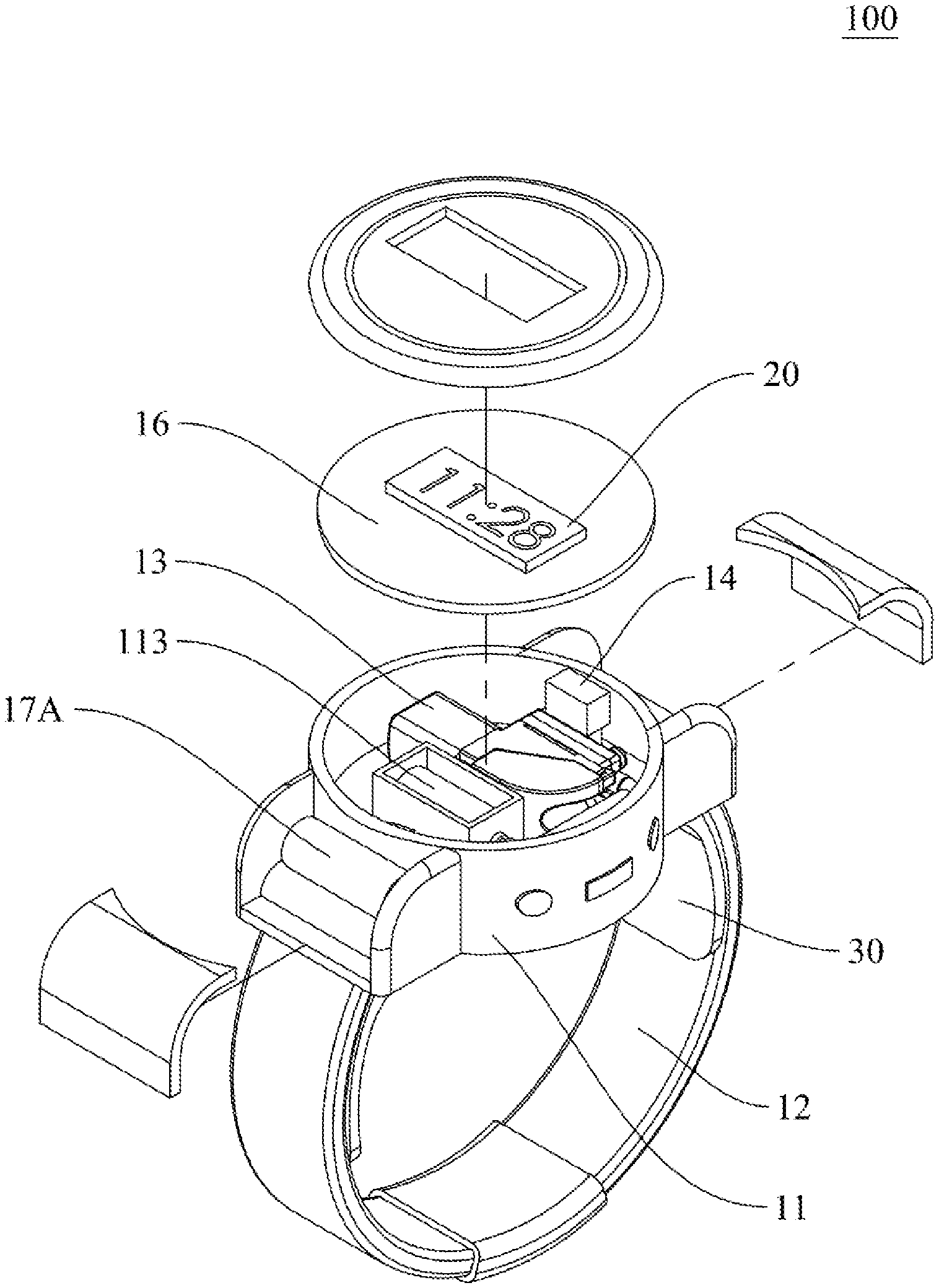
[0024] FIG. 3 is an exploded perspective view of the wearable device of the present invention.
[0025] FIG. 4 shows two assembled sectional views of the detachable bladder in the present invention.
[0026] FIG. 5 shows a plurality of different configurations of the detachable bladder in the present invention.
[0027] FIG. 6 shows a plurality of different configurations of the detachable bladder in the present invention.
[0028] FIG. 7 shows how the detachable bladder is detached from the watch case of the wearable device of the present invention.
[0029] FIG. 8 is a schematic diagram of the internal structure of the wearable device of the present invention.
[0030] FIG. 9 shows the air intake flow path of the detachable bladder of the present invention.
[0031] FIG. 10 shows the air discharge flow path of the detachable bladder of the present invention.
DETAILED DESCRIPTION OF THE INVENTION
[0032] The details and technical solution of the present invention are hereunder described with reference to accompanying drawings. For illustrative sake, the accompanying drawings are not drawn to scale. The accompanying drawings and the scale thereof are not restrictive of the present invention.
[0033] The present invention provides a wearable device capable of blood pressure measurement. The wearable device may be worn on a user's wrist or forearm in order to measure the user's physiological indices in real time or ambulatorily at regular intervals.
[0034] It should be pointed out that, while the subject matter of the present invention is a wearable device capable of blood pressure measurement, the wearable device disclosed herein can, in addition to calculating a user's systolic pressure and diastolic pressure by means of an algorithm, derive the user's heart rhythm parameters from the data detected by a sensor and determine whether the user has irregular pulse peaks, irregular heartbeat, atrial fibrillation, or other symptoms according to the heart rhythm parameters obtained and using applicable algorithms.
[0035] Furthermore, the wearable device of the present invention can communicate with the user's mobile device through firmware and a wireless transmission means such as Bluetooth, infrared (IR) transmission, near-field communication (NFC), ultra-wideband (UWB), wireless local area networks (WLAN), Wireless Gigabit Alliance (WiGig Alliance) communications technology, ZigBee, wireless universal serial bus (wireless USB), or Wi-Fi, in order for the mobile device to record the user's physiological data, send out an emergency notification, transmit data to a hospital, or update the firmware of the wearable device. In one preferred embodiment, the wearable device is also provided with a global positioning system (GPS) module, a motion sensor chip, an acceleration sensor, an electronic compass, and so on in order to obtain data about the user's movement and monitor the user's condition in real time based on the data obtained.
[0036] Moreover, the wearable device of the present invention can load and be installed with a third-party program in order for the third-party program to expand the functions of the hardware of the wearable device and thereby render the wearable device more useful.
[0037] Please refer to FIG. 1 to FIG. 3 respectively for an assembled perspective view, a block diagram, and an exploded perspective view of the wearable device of the present invention.
[0038] The present invention provides a wearable device 100 that includes a wrist band assembly 10, a display unit 20 provided on the wrist band assembly 10, and a detachable bladder 30 provided on the backside of the wrist band assembly 10. In this embodiment, the wearable device 100 is in the form of a watch, but other than having the shape and functions of a watch, the wearable device 100 may also be implemented as a health bracelet or sports bracelet; the present invention has no limitation in this regard.
[0039] In this embodiment, the wrist band assembly 10 includes a watch case 11 and a wrist band 12 coupled to the watch case 11. The detachable bladder 30 is not coupled to the wrist band 12 but is connected to the backside of the watch case 11 by a detachable means. The detachable means may be, for example, riveting, threaded connection, mechanical fastening, mechanical engagement, or other similar mechanisms; the present invention has no limitation in this regard. The phrase "not coupled to the wrist band" indicates that the detachable bladder 30 and the wrist band 12 are two separate components, and that the detachable bladder 30 can be detached from the watch case 11 independently of the wrist band 12. This configuration is different from the typical co-constructed configuration of a conventional sphygmomanometer bladder and the corresponding arm strap (or wrist band). The wrist band assembly 10 is provided with a micro air pump 13, an air pressure sensor 14, and a processor 15.
[0040] The watch case 11 is configured to accommodate the micro air pump 13, air pressure sensor 14, processor 15, and display unit 20 installed therein. The air pressure sensor 14, the processor 15, and the display unit 20 can be integrated into a circuit board 16 in order to be electrically connected to other electronic components (e.g., the micro air pump 13 and a pressure relief valve 113 (see FIG. 3)) via the connection ports on the circuit board 16. The circuit board 16 also serves as a partition in the watch case 11 and separates the electronic components from the electromechanical components. The watch case 11 may be provided on one side with physical buttons, a touch panel, or other similar input units connected to the circuit board 16 so that a user can input commands into the wearable device 100 through the input unit(s), and the present invention has no limitation on the type of the input unit(s). In one preferred embodiment, the watch case 11 is provided therein with a shielding structure to protect the electronic components (including the processor 15) from electromagnetic interference (EMI). In another preferred embodiment, the watch case 11 is further provided, either internally or externally, with a battery-based power source module 17, and the battery in the power source module 17 can be replaced with a new one of the same model number when dead. In yet another preferred embodiment, the power source module 17 includes a battery holder 17A to facilitate battery replacement. In still another preferred embodiment, the wearable device 100 is directly provided with a charging module so that the battery in the power source module 17 can be charged by an external power source through a mini USB, micro USB, or USB type-C connector, on whose type the present invention has no limitation.
[0041] The micro air pump 13 is connected to the detachable bladder 30 and is configured to compress air and provide a target space with a positive pressure, i.e., a higher air pressure than the ambient air pressure. Thus, by means of pressurization, the micro air pump 13 can be used to inflate the detachable bladder 30. The micro air pump 13 may be a diaphragm pump, an electromagnetic pump, a centrifugal pump, or a reciprocating air pump; the present invention has no limitation in this regard.
[0042] The air pressure sensor 14 is integrated into the circuit board 16 and is located on one side of the detachable bladder 30. The air pressure sensor 14 has a probe to be inserted into a second tubular base 115 (see FIG. 4) in the watch case 11. The interior space of the second tubular base 115 is intended to communicate with the interior space of the detachable bladder 30 so that the air pressure sensor 14 can detect the internal pressure of the detachable bladder 30 through the second tubular base 115, the objective being to derive a user's pulse rate from the variation in resonance between the internal pressure and the user's pulse, and to calculate the user's systolic pressure and diastolic pressure by an algorithm. The air pressure sensor 14 may be an absolute pressure sensor, a gauge pressure sensor, a vacuum pressure sensor, a differential pressure sensor, or a sealed pressure sensor; the present invention has no limitation in this regard.
[0043] The processor 15 is connected to the micro air pump 13 and the air pressure sensor 14. The processor 15 activates the micro air pump 13 according to a trigger signal, in order for the micro air pump 13 to inflate the detachable bladder 30 and for the user's blood pressure parameters to be derived from the data sent by the air pressure sensor 14 to the processor 15. More specifically, the processor 15 is configured to load and execute the program(s) in a storage unit, to control the operation of the other electronic components and electromechanical components of the wearable device 100 through the program(s), and to perform computation. In one preferred embodiment, and by way of example only, the processor 15 and the storage unit form a co-constructed processor. The processor 15 may be a central processing unit (CPU), a programmable general-purpose or special-purpose microcontroller unit (MCU), a digital signal processor (DSP), a programmable controller, an application-specific integrated circuit (ASIC), other similar devices, or a combination of the above.
[0044] The display unit 20 is configured to display a detection result (e.g., a user's blood pressure data, heart rhythm data, or other health data, such as the number of the steps the user has taken and the walking time) when detection is completed. In addition to displaying the aforesaid data, the display unit may provide a control interface or graphical user interface (GUI) whereby a user can operate or set the wearable device; the present invention has no limitation in this regard. The display unit 20 may be an organic light-emitting diode (OLED) display panel, an in-plane switching (IPS) liquid crystal display panel, a low-temperature poly-silicon (LTPS) display panel, an indium gallium zinc oxide (IGZO) display panel, a vertical alignment (VA) liquid crystal display panel, a quantum dot display panel, or electronic paper (epaper). In one preferred embodiment, the display unit 20 is a touch panel. The present invention has no limitation on the type of the display unit 20.
[0045] The structural details of the detachable bladder 30 are described below with reference to FIG. 4, FIG. 5, FIG. 6, and FIG. 7, which show two assembled sectional views of the detachable bladder, a plurality of different configurations of the detachable bladder, and how the detachable bladder is detached from the watch case of the wearable device.
[0046] As shown in FIG. 4, the detachable bladder 30 is connected to the backside of the watch case 11 by a detachable means without being coupled to the wrist band 12. The detachable bladder 30 includes a hollow bladder body 31, two bladder wings 32 that extend from the hollow bladder body 31 in two opposite lateral directions respectively, an air delivery hole 33, and an air pressure detection hole 34, the latter two of which are provided at the hollow bladder body 31. The bilaterally extending bladder wings 32 of the detachable bladder 30 extend along the wrist band 12. In one preferred embodiment, the detachable means includes airtight annular posts 331 and 341 that are provided respectively at the air delivery hole 33 and the air pressure detection hole 34 to produce an airtight effect. By inserting the airtight annular posts 331 and 341 into the corresponding sockets (i.e., the first tubular base and the second tubular base) respectively, each annular post is pressed tightly against the inner wall of the corresponding socket to achieve not only airtightness, but also high air delivery efficiency and watertightness.
[0047] As shown in FIG. 7, the detachable bladder 30 is secured in position by inserting the airtight annular posts 331 and 341 into the corresponding sockets respectively and can be easily detached for replacement.
[0048] In order for the detachable bladder 30 to lie compliantly on a user's wrist, thereby ensuring that the detachable bladder 30 will occlude the user's blood vessels in the wrist to enable accurate blood pressure measurement, the bilateral bladder wings 32 of the detachable bladder 30 are each provided with an arcuate supporting plate 35 that curves along the user's wrist. When inflated, therefore, the hollow bladder body 31 will conform to the curvature of and be pressed tightly against the user's wrist. The arcuate supporting plates 35 may be provided on the side of the detachable bladder 30 that is adjacent to or faces away from the user's skin. In one preferred embodiment, the arcuate supporting plates 35 are provided on the side of the detachable bladder 30 that faces away from the user's skin to provide better occlusion. In another embodiment, the arcuate supporting plates 35 may be integrally formed with or be separate from the detachable bladder 30. In one preferred embodiment, the arcuate supporting plates 35 are integrally formed with the detachable bladder 30 to reduce the required number of molds and to enhance the look of the end product.
[0049] In the illustrated embodiment, the hollow bladder body 31 is circular to match the circular shape of the watch case 11. Alternatively, the hollow bladder body 31 may be non-circular to match a differently shaped watch case 11 or to follow the principle of ergonomic design; the present invention has no limitation in this regard.
[0050] Referring now to FIG. 5, the air delivery hole 33 and the air pressure detection hole 34 of the detachable bladder 30 in one preferred embodiment are provided at the hollow bladder body 31 in such a way that an imaginary line connecting the two holes is parallel to the wrist band 12. Once the wearable device is worn on a user's limb, the imaginary line connecting the air delivery hole 33 and the air pressure detection hole 34 is perpendicular to the user's limb. This arrangement allows the detachable bladder 30 to compress the arteries in the limb sufficiently when inflated, so a desirable resonance waveform and high measurement accuracy ensue. The bladder wings 32 extending respectively from the two opposite lateral sides of the hollow bladder body 31 may vary in length, depending on the circumference of the user's limb. The total length of the bladder wings 32 and the hollow bladder body 31 may range from 60 mm to 150 mm. For example, the total length of the bladder wings 32 and the hollow bladder body 31 may be 75 mm (as in the case with the bladder wings 32A and the hollow bladder body 31A of the detachable bladder 30A in FIG. 5), 95 mm (as in the case with the bladder wings 32B and the hollow bladder body 31B of the detachable bladder 30B in FIG. 5), 115 mm (as in the case with the bladder wings 32C and the hollow bladder body 31C of the detachable bladder 30C in FIG. 5), or 135 mm (as in the case with the bladder wings 32D and the hollow bladder body 31D of the detachable bladder 30D in FIG. 5); the present invention has no limitation in this regard. In one preferred embodiment, the length of the detachable bladder 30 is generally equal to 0.5 to 0.8 times the circumference of the wrist band 12. When the length of the detachable bladder 30 is about 0.8 times the circumference of the wrist band 12 and the width of the detachable bladder 30 is generally equal to 0.4 to 0.6 times the length of the detachable bladder 30, the wearable device is expected to have high detection accuracy while causing relatively little discomfort to the human body.
[0051] In another preferred embodiment, referring to FIG. 6, the air delivery hole 33 and the air pressure detection hole 34 of the detachable bladder 30 are provided at the hollow bladder body 31 in such a way that an imaginary line connecting the two holes is perpendicular to the wrist band 12. Once the wearable device is worn on a user's limb, the imaginary line connecting the air delivery hole 33 and the air pressure detection hole 34 is parallel to the user's limb. When the air delivery hole 33 and the air pressure detection hole 34 are so arranged, the total length of the bladder wings 32 and the hollow bladder body 31 may be, for example, 75 mm (as in the case with the bladder wings 32E and the hollow bladder body 31E of the detachable bladder 30E in FIG. 6), 95 mm (as in the case with the bladder wings 32F and the hollow bladder body 31F of the detachable bladder 30F in FIG. 6), 115 mm (as in the case with the bladder wings 32G and the hollow bladder body 31G of the detachable bladder 30G in FIG. 6), or 135 mm (as in the case with the bladder wings 32H and the hollow bladder body 31H of the detachable bladder 30H in FIG. 6); the present invention has no limitation in this regard. In one preferred embodiment, the length of the detachable bladder 30 is generally equal to 0.5 to 0.8 times the circumference of the wrist band 12. When the length of the detachable bladder 30 is about 0.8 times the circumference of the wrist band 12 and the width of the detachable bladder 30 is generally equal to 0.4 to 0.6 times the length of the detachable bladder 30, the wearable device is expected to have high detection accuracy while causing relatively little discomfort to the human body.
[0052] The internal structure and air delivery paths of the wearable device 100 are detailed below with reference to FIG. 8, which shows a schematic diagram of the internal structure of the wearable device of the present invention.
[0053] As shown in FIG. 8, the watch case 11 is provided therein with a connecting tube 111, a branch tube 112 in communication with the connecting tube 111, and a pressure relief valve 113 provided at one end of the branch tube 112. The connecting tube 111 has one end connected to the air outlet of the micro air pump 13 and the opposite end connected to the first tubular base 114 of the watch case 11. The first tubular base 114 is configured to be inserted by the airtight annular post 331 at the air delivery hole 33 of the hollow bladder body 31 so that the air in the micro air pump 13 can be guided into and thereby inflate the detachable bladder 30. The processor 15 is connected to the pressure relief valve 113 and is configured to trigger and thereby open the pressure relief valve 113 conditionally (typically when detection is completed or when receiving a trigger command resulting from the user's forced activation of the pressure relief valve), in order to guide the air in the hollow bladder body 31 through the branch tube 112 and the pressure relief valve 113 to a pressure relief hole 1131 at one side of the watch case 11.
[0054] In addition to the foregoing tubes for air delivery, the watch case 11 is provided with the second tubular base 115, which, as stated above, is configured to be inserted by the probe 141 of the air pressure sensor 14. The probe 141 is inserted into the airtight annular post 341 at the air pressure detection hole 34 of the hollow bladder body 31 so that the air pressure sensor 14 on the second tubular base 115 can detect the air pressure parameters inside the hollow bladder body 31.
[0055] The flow paths along which air enters or is discharged from the detachable bladder 30 are described below with reference to FIG. 9 and FIG. 10, which show the air intake flow path and air discharge flow path of the detachable bladder of the present invention respectively.
[0056] To inflate the detachable bladder 30, referring to FIG. 9, the processor 15 sends a command to the micro air pump 13 and thereby drives the micro air pump 13 to pressurize the connecting tube 111. As a result, air is delivered from the micro air pump 13 through the connecting tube 111 to the air delivery hole 33 and then into the detachable bladder 30. While the detachable bladder 30 is being inflated, the pressure in the detachable bladder 30 is transmitted to the second tubular base 115 in order for the air pressure sensor 14 on the second tubular base 115 to detect the air pressure in the detachable bladder 30.
[0057] To deflate the detachable bladder 30, referring to FIG. 10, the processor 15 sends a control command to and thereby opens the pressure relief valve 113 upon receiving a trigger command for air discharge (e.g., when detection is completed or due to a forced shutdown of the wearable device by the user). Once the pressure relief valve 113 is opened, the air in the detachable bladder 30 is driven to the connecting tube 111 through the air delivery hole 33 by the higher air pressure in the detachable bladder 30 than the ambient air pressure and, after passing through the branch tube 112, is discharged via the pressure relief hole 1131 of the pressure relief valve 113.
[0058] According to the above, the wearable device capable of blood pressure measurement according to the present invention can be put on conveniently for 24-hour ambulatory blood pressure monitoring at a fixed time interval, allowing a physician to determine whether the user has hypertension or prehypertension. In addition, the wearable device capable of blood pressure measurement according to the present invention can reduce the discomfort of blood pressure measurement and thereby provide better user experience than its prior art counterparts. Moreover, the wearable device capable of blood pressure measurement according to the present invention can reduce sensing errors attributable to sweat on the skin as are typical of the conventional optical sensing methods. The wearable device, therefore, is suitable as a personal daily health care device for monitoring the risk of cardiovascular diseases. Furthermore, the wearable device capable of blood pressure measurement according to the present invention is suitable for use in ambulances, emergency rooms, intensive care units, hospital wards, clinics, and other medical institutions, and can be worn by each patient in order for such big data as patients' blood pressures and heart rhythms to be monitored and recorded through the Internet of Things. The wearable device, therefore, has utility value in the medical industry. The bladder and wrist band in the present invention are detachable from each other so that a user can detach either of them as desired and replace it with a wrist band/bladder of a different color, pattern, or shape.
[0059] The above is the detailed description of the present invention. However, the above is merely the preferred embodiment of the present invention and cannot be the limitation to the implement scope of the present invention, which means the variation and modification according to the present invention may still fall into the scope of the invention.
* * * * *
D00000
D00001
D00002
D00003
D00004
D00005
D00006
D00007
D00008
D00009
D00010
XML
uspto.report is an independent third-party trademark research tool that is not affiliated, endorsed, or sponsored by the United States Patent and Trademark Office (USPTO) or any other governmental organization. The information provided by uspto.report is based on publicly available data at the time of writing and is intended for informational purposes only.
While we strive to provide accurate and up-to-date information, we do not guarantee the accuracy, completeness, reliability, or suitability of the information displayed on this site. The use of this site is at your own risk. Any reliance you place on such information is therefore strictly at your own risk.
All official trademark data, including owner information, should be verified by visiting the official USPTO website at www.uspto.gov. This site is not intended to replace professional legal advice and should not be used as a substitute for consulting with a legal professional who is knowledgeable about trademark law.