Elongate Elastic Member For Use In Lower-body Garments
Achtymichuk; Amie J. ; et al.
U.S. patent application number 16/570587 was filed with the patent office on 2020-03-19 for elongate elastic member for use in lower-body garments. The applicant listed for this patent is NIKE, Inc.. Invention is credited to Amie J. Achtymichuk, Oksana Anilionyte, Baron C. Brandt, Joseph L. Helseth, Alison Sheets-Singer, Alexander S. Siegel.
| Application Number | 20200085123 16/570587 |
| Document ID | / |
| Family ID | 69773581 |
| Filed Date | 2020-03-19 |


View All Diagrams
| United States Patent Application | 20200085123 |
| Kind Code | A1 |
| Achtymichuk; Amie J. ; et al. | March 19, 2020 |
ELONGATE ELASTIC MEMBER FOR USE IN LOWER-BODY GARMENTS
Abstract
An elongate elastic member for assisting an athletic motion and a lower-body garment incorporating the elongate elastic member are provided herein. The elongate elastic member may have various configurations that permit it to be attached to a foot or shoe of a wearer and a torso of the wearer. The structure and as-worn configuration of the elongate elastic member and associated lower-body garment augment or inhibit joint moments during an athletic motion, improving the actual or perceived amount of energy expended to complete the athletic motion.
| Inventors: | Achtymichuk; Amie J.; (Portland, OR) ; Anilionyte; Oksana; (Beaverton, OR) ; Brandt; Baron C.; (Portland, OR) ; Helseth; Joseph L.; (Plano, TX) ; Sheets-Singer; Alison; (Beaverton, OR) ; Siegel; Alexander S.; (Beaverton, OR) | ||||||||||
| Applicant: |
|
||||||||||
|---|---|---|---|---|---|---|---|---|---|---|---|
| Family ID: | 69773581 | ||||||||||
| Appl. No.: | 16/570587 | ||||||||||
| Filed: | September 13, 2019 |
Related U.S. Patent Documents
| Application Number | Filing Date | Patent Number | ||
|---|---|---|---|---|
| 62731604 | Sep 14, 2018 | |||
| Current U.S. Class: | 1/1 |
| Current CPC Class: | A41D 13/0015 20130101; A63B 21/0555 20130101; A41D 2300/22 20130101; A63B 21/0552 20130101; A63B 21/4013 20151001; A63B 21/4009 20151001; A41D 31/185 20190201; A63B 21/065 20130101; A63B 21/0407 20130101; A41D 1/08 20130101; A41D 2500/20 20130101; A41D 2600/10 20130101; A41F 15/02 20130101; A63B 21/4011 20151001; A41D 2500/10 20130101 |
| International Class: | A41D 31/18 20060101 A41D031/18; A41D 1/08 20060101 A41D001/08 |
Claims
1. A lower-body garment comprising: a torso portion having a waist opening; a first leg portion and a second leg portion extending from the torso portion, the first leg portion defining a first leg opening and the second leg portion defining a second leg opening; a first textile layer having a first surface and a second surface opposite the first surface; a second textile layer positioned at least at a first area of the lower-body garment, the second textile layer having a third surface and a fourth surface opposite the third surface, where the third surface of the second textile layer is positioned adjacent to the second surface of the first textile layer at the first area of the lower-body garment; and a first elongate elastic member continuously extending from a first location adjacent to the first leg opening to a second location adjacent to the waist opening, the first elongate elastic member at least partially disposed between the first textile layer and the second textile layer at the first area of the lower-body garment.
2. The lower-body garment of claim 1, wherein the first elongate elastic member is disposed on an anterior side of the lower-body garment in a first zone, disposed on a posterior side of the lower-body garment in a third zone, and disposed on both a medial side and a lateral side of the lower-body garment in a second zone.
3. The lower-body garment of claim 2, wherein the third zone is disposed between the first zone and the second zone.
4. The lower-body garment of claim 1, the first elongate elastic member further comprising a stirrup configured for receiving a foot of a wearer.
5. The lower-body garment of claim 1, the first elongate elastic member further comprising one or more adjusting components operably configured to modify a length of the first elongate elastic member.
6. The lower-body garment of claim 1, wherein at a second area of the lower-body garment, the lower-body garment comprises the first textile layer and not the second textile layer, and wherein the first elongate elastic member is disposed adjacent to the second surface of the first textile layer at the second area.
7. The lower-body garment of claim 1, wherein the first elongate elastic member further continuously extends from the second location adjacent to the waist opening, to a third location adjacent to the second leg opening.
8. The lower-body garment of claim 1, wherein the lower-body garment further comprises a second elongate elastic member, the second elongate elastic member continuously extending from a third location adjacent to the second leg opening to the second location adjacent to the waist opening.
9. The lower-body garment of claim 8, wherein the first elongate elastic member is coupled to the second elongate elastic member.
10. An elongate elastic member for assisting an athletic motion comprising: a first end, a second end opposite the first end, and an intervening length therebetween; and at least a first slit and a second slit, each of the first slit and the second slit disposed lengthwise parallel to a longitudinal axis of the elongate elastic member.
11. The elongate elastic member of claim 10, further comprising a third slit positioned adjacent to the second end, the third slit disposed lengthwise parallel to the longitudinal axis of the elongate elastic member.
12. The elongate elastic member of claim 10, further comprising a pair of apertures positioned adjacent to the second end, the pair of apertures configured to be coupled to a shoelace of a shoe of a wearer.
13. The elongate elastic member of claim 10, further comprising a stirrup extending from the second end, the stirrup configured to receive a foot of a wearer.
14. The elongate elastic member of claim 10, further comprising an adjusting component coupled to the elongate elastic member, the adjusting component configured to operably adjust a length of the elongate elastic member.
15. A lower-body garment comprising: a torso portion having a waist opening; a first leg portion and a second leg portion extending from the torso portion, the first leg portion defining a first leg opening and the second leg portion defining a second leg opening; a first area comprising: a first textile layer having a first surface and a second surface opposite the first surface, and a second textile layer having a third surface and a fourth surface opposite the third surface, wherein the third surface of the second textile layer is positioned adjacent to the second surface of the first textile layer at the first area; a second area comprising the first textile layer and not the second textile layer; and an elongate elastic member continuously extending from a location adjacent to the first leg opening, to a location adjacent to the waist opening, to a location adjacent to the second leg opening, the elongate elastic member disposed between the first textile layer and the second textile layer at the first area, the elongate elastic member further disposed on the second surface of the first textile layer at the second area.
16. The lower-body garment of claim 15, wherein the elongate elastic member is disposed in the first area on a lateral side of the lower-body garment and disposed in the second area on a medial side of the lower-body garment.
17. The lower-body garment of claim 15, wherein the elongate elastic member further comprises a stirrup configured for receiving a foot of a wearer.
18. The lower-body garment of claim 15, wherein the second textile layer is integrally knit or woven with the first textile layer.
19. The lower-body garment of claim 15, wherein the second textile layer is a separate panel piece from the first textile layer, and wherein the first textile layer and the second textile layer are coupled together at one or more perimeter edges of the second textile layer.
20. The lower-body garment of claim 15, wherein the elongate elastic member further comprises a plurality of adjusting components operably configured to modify a length of the elongate elastic member.
Description
CROSS-REFERENCE TO RELATED APPLICATIONS
[0001] This application, having attorney docket number 331271/170352US02 and entitled "Elongate Elastic Member for use in Lower-Body Garments," claims priority to U.S. Provisional Patent Application No. 62/731,604, filed Sep. 14, 2018, and entitled, "Elongate Elastic Member for use in Lower-Body Garments," the entirety of which is incorporated herein by reference.
TECHNICAL FIELD
[0002] Aspects herein relate to elongate elastic members and lower-body garments featuring one or more elongate elastic members configured to have a kinesiologic effect on a wearer.
BACKGROUND
[0003] Running, whether recreationally or competitively, is a cardiovascular activity often involving high metabolic cost. Whether running for general fitness or competing, runners often experience muscle and joint fatigue in the lower-body before achieving the desired cardiovascular effect. Further, some runners may use improper form when running, increasing the likelihood they will injure one or more muscles, tendons, or ligament groups (e.g., hip flexors, knee ligaments, Achilles tendon).
BRIEF DESCRIPTION OF THE DRAWINGS
[0004] Examples of the present invention are described in detail below with reference to the attached drawing figures, wherein:
[0005] FIG. 1 illustrates an example elongate elastic member for assisting an athletic motion wherein the elastic member comprises a split or bifurcated first end in accordance with aspects herein;
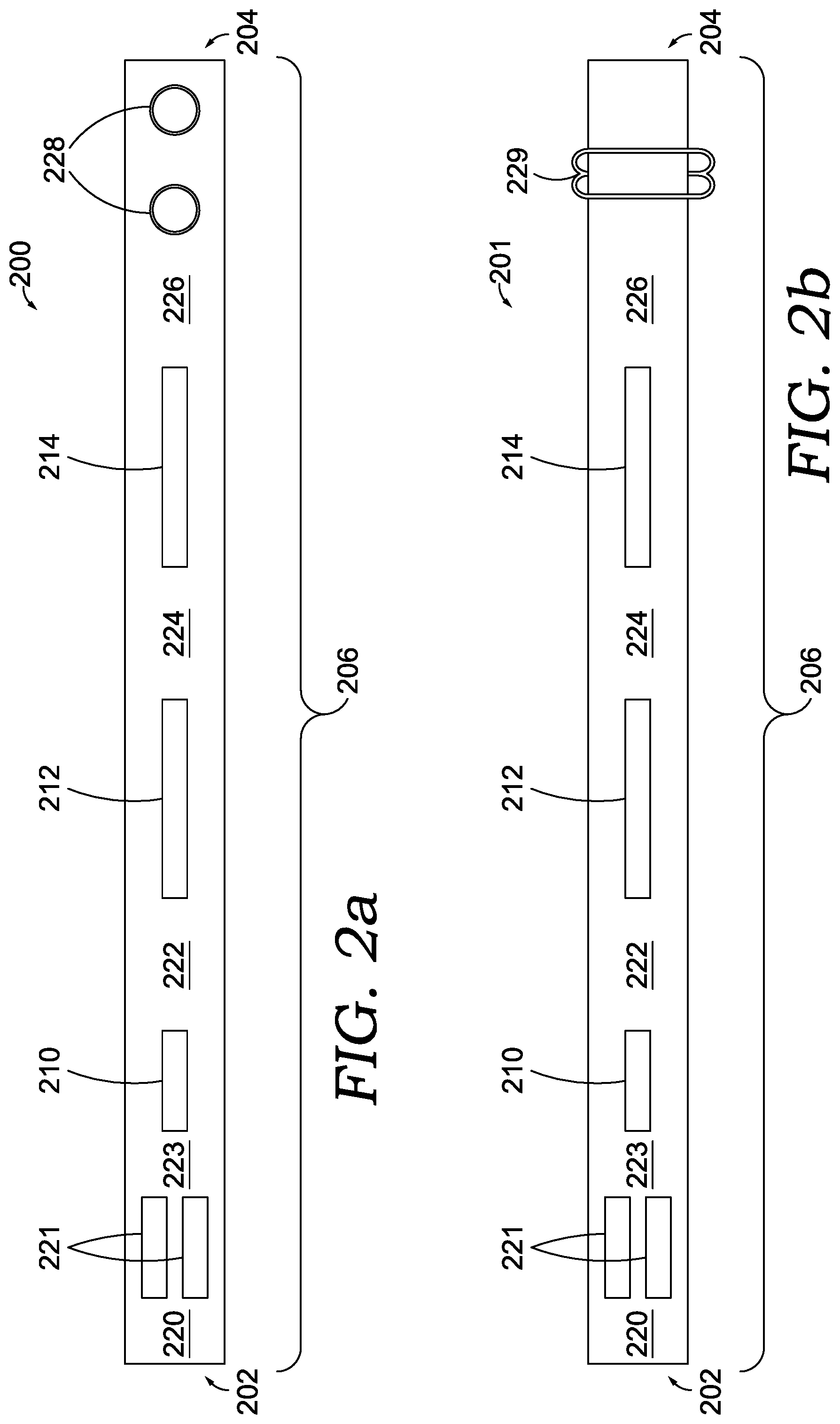
[0006] FIG. 2a illustrates an example elongate elastic member having anchors for attaching the elongate elastic member to a torso or a wearer and apertures configured to be coupled to a shoelace of a shoe of a wearer in accordance with aspects herein;
[0007] FIG. 2b illustrates an example elongate elastic member having an adjusting component and apertures configured to be coupled to a shoelace of a shoe of a wearer in accordance with aspects herein;
[0008] FIG. 2c illustrates an example elongate elastic member constructed of a first elastic strip and a second elastic strip in accordance with aspects herein;
[0009] FIG. 3 illustrates another alternative elongate elastic member having a stirrup configured to receive a foot of a wearer in accordance with aspects herein;
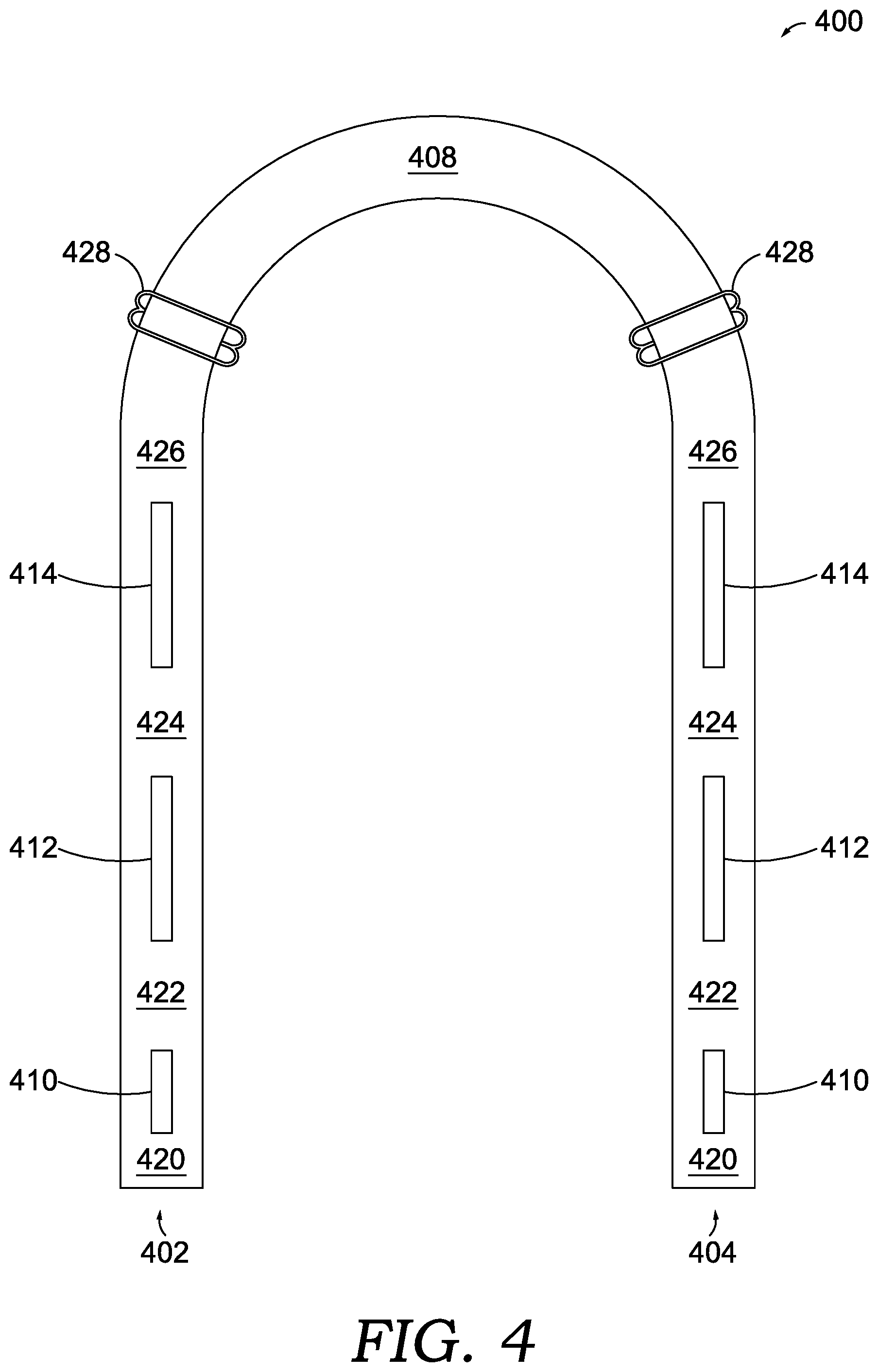
[0010] FIG. 4 illustrates yet another elongate elastic member configured to continuously extend from a first leg opening of a lower-body garment to a waist opening of the garment, to a second leg opening of the garment in accordance with aspects herein;
[0011] FIG. 5a illustrates a front view of an example lower-body garment having an elongate elastic member at least partially disposed between a first and second textile layer at one or more portions of the lower-body garment in accordance with aspects herein;
[0012] FIG. 5b illustrates a back view of the lower-body garment of FIG. 5a in accordance with aspects herein;
[0013] FIG. 5c illustrates a side view of the lateral aspect of the lower-body garment of FIG. 5a in accordance with aspects herein;
[0014] FIG. 5d illustrates a side view of the medial aspect of the lower-body garment of FIG. 5a in accordance with aspects herein;
[0015] FIG. 5e illustrates an example stirrup configuration having tread-like features incorporated therewith in accordance with aspects hereof;
[0016] FIG. 5f illustrates an example stirrup configuration having a straddle formed by a first stirrup strap and a second stirrup strap in accordance with aspects hereof;
[0017] FIG. 6a illustrates a front view of an example lower-body garment having an elongate elastic member at least partially disposed between a first and second textile layer on one or more portions of the lower-body garment in accordance with aspects herein;
[0018] FIG. 6b illustrates a back view of the lower-body garment of FIG. 6a in accordance with aspects herein;
[0019] FIG. 6c illustrates a side view of the lower-body garment of FIG. 6a in accordance with aspects herein;
[0020] FIG. 7a illustrates a cross-sectional view of a portion of the example lower-body garment of FIGS. 5a-5d and 6a-6c depicting a first alternative construction having a first textile layer and second textile layer coupled at a perimeter edge of the second textile layer, in accordance with aspects herein;
[0021] FIG. 7b illustrates a cross-sectional view of a portion of the example lower-body garment of FIGS. 5a-5d and 6a-6c depicting a second alternative construction having a first textile layer and second textile layer coupled at multiple points, in accordance with aspects herein;
[0022] FIG. 7c illustrates a cross-sectional view of a portion of the example lower-body garment of FIGS. 5a-5d and 6a-6c depicting a third alternative construction having an integrally knit first textile layer and second textile layer, in accordance with aspects herein;
[0023] FIG. 8a illustrates a cross section of a first tread pattern that may implemented in connection with a stirrup in accordance with aspects hereof;
[0024] FIG. 8b illustrates a cross section of a second tread pattern that may implemented in connection with a stirrup in accordance with aspects hereof;
[0025] FIG. 8c illustrates a cross section of a third tread pattern that may implemented in connection with a stirrup in accordance with aspects hereof; and
[0026] FIG. 8d illustrates a cross section of a fourth tread pattern that may implemented in connection with a stirrup in accordance with aspects hereof.
DETAILED DESCRIPTION
[0027] The subject matter of the present invention is described with specificity herein to meet statutory requirements. However, the description itself is not intended to limit the scope of this disclosure. Rather, the inventors have contemplated that the claimed or disclosed subject matter might also be embodied in other ways, to include different steps or combinations of steps similar to the ones described in this document, in conjunction with other present or future technologies. Moreover, although the terms "step" and/or "block" might be used herein to connote different elements of methods employed, the terms should not be interpreted as implying any particular order among or between various steps herein disclosed unless and except when the order of individual steps is explicitly stated.
[0028] By way of background, it may be desirable to assist an athletic motion, such as running, by augmenting or inhibiting a joint moment (force applied or motion about a point or axis), or by creating a perception in a wearer that the athletic motion is easier to perform. For example, a recreational runner may find it helpful to have a device or garment comprising a device that assists with knee flexion during a running stride. By augmenting the joint moment associated with knee flexion, the runner may more efficiently use their hamstrings and quadriceps during the stride, reducing the actual or perceived energy expenditure required to run. In so doing, the runner may be enabled to run farther or run faster, for example. Conventionally, devices that augment joint moments tend to be bulky, rigid, unwieldy, or difficult to don and doff--significantly reducing their usefulness outside of rehabilitation or laboratory environments. In order to assist with an athletic motion, aspects herein contemplate an elongate elastic member and a lower-body garment comprising an elongate elastic member that augment joint moments, is conveniently used in multiple configurations, and is easily donned and doffed.
[0029] At a high level, aspects herein relate to an elongate elastic member and lower-body garments incorporating the elastic member. In example aspects, the elongate elastic member assists an athletic motion, such as running, where the elastic member has a first end and a second end, and an intervening portion continuously extending between the first end and the second end. Disposed on the intervening portion, the elongate elastic member comprises at least a first slit and a second slit, each of the first slit and the second slit disposed lengthwise parallel to a longitudinal axis of the elongate elastic member. In some aspects, the intervening portion may also comprise a third slit for receiving the foot or shoe of a wearer, a pair of apertures configured to be coupled to a shoelace of a shoe of the wearer, and/or a stirrup configured to receive the foot or shoe of the wearer. The elastic member may, in aspects, comprise various features that facilitate anchoring the first end to an area adjacent to the torso of the wearer.
[0030] Continuing, the elastic member can be donned in various orientations that impart varying kinesiologic effects on a wearer. For example, a wearer can don the elastic member such that the first end is disposed on an anterior portion of the wearer's lower torso, the thigh/upper leg extends through an opening formed by the first slit and the lower leg extends through an opening formed by the second slit, where the intervening portion of the elastic member between the first slit and the second slit is disposed on the posterior side of the leg. In such an orientation, the elastic member may augment joint moments generated during the swing phase of a running motion, including ankle dorsiflexion, knee flexion, and/or hip flexion. The aforementioned as-donned orientation is but one application of the elastic member; in other as-donned orientations, the elastic member may supplement ankle moment at push off and augment ankle plantarflexion, knee flexion, and/or hip flexion during the swing phase. In yet another as-donned orientation, the elastic member may augment joint moments generated during the stance phase of a running motion, including ankle plantarflexion, knee flexion, and/or hip extension. In any orientation, the augmentation of joint moments may provide kinesiologic benefits that make running easier or more efficient and/or may provide a user with the perception or sensation that running feels easier.
[0031] When aspects of the elastic member are integrated into a lower-body garment, the elastic member may be positioned such that it is at least partially disposed between a first textile layer and a second textile layer of the lower-body garment in one or more portions of one or more zones of the lower-body garment. By at least partially disposing portions of the elastic member between the textile layers, the elastic member is less likely to move from a desired as-donned orientation to an undesired orientation. Further, by incorporating aspects of the elastic member into the lower-body garment, a wearer can more easily don the elastic member and use it as intended. In aspects where the elastic member comprises a detachable stirrup or a stirrup that can be concealed, the lower-body garment may permit a wearer to convert the lower-body garment from a functional, running-augmenting garment, to more of an aesthetic garment without having the stirrup protruding from a location adjacent to the leg opening of the lower-body garment.
[0032] Accordingly, aspects herein are directed to a lower-body garment comprising a torso portion having a waist opening, a first leg portion defining a first leg opening, and a second leg portion defining a second leg opening. The lower-body garment may comprise a first textile layer having a first surface and a second surface opposite the first surface, and a second textile layer, positioned at least at a first area of the lower-body garment, having a third surface and a fourth surface, wherein the third surface of the second textile layer is positioned adjacent to the second surface of the first textile layer in the first area of the lower-body garment. The lower-body garment may also comprise a first elongate elastic member that continuously extends from a first location adjacent to the first leg opening to a second location adjacent to the waist opening, and which is at least partially disposed between the first textile layer and the second textile layer at the first area of the lower-body garment.
[0033] Aspects herein are additionally directed to a lower-body garment comprising a torso portion having a waist opening, a first leg portion defining a first leg opening, and a second leg portion defining a second leg opening. The lower-body garment has a first area comprising a first textile layer having a first surface and a second surface opposite the first surface, and a second textile layer having a third surface and a fourth surface opposite the third surface, wherein the third surface of the second textile layer is positioned adjacent to the second surface of the first textile layer at the first area. The lower-body garment also has a second area comprising the first textile layer and not the second textile layer. The lower-body garment additionally comprises an elongate elastic member continuously extending from a location adjacent to the first leg opening, to a location adjacent to the waist opening, to a location adjacent to the second leg opening, where the elongate elastic member is disposed between the first textile layer and the second textile layer at the first area, and the elongate elastic member is further disposed on the second surface of the first textile layer at the second area.
[0034] Additional aspects herein are directed to an elongate elastic member for assisting an athletic motion. The elongate elastic member has a first end, a second end opposite the first end, and an intervening length therebetween. The elongate elastic member may comprise at least a first slit and a second slit, each of the first slit and the second slit being disposed lengthwise parallel to a longitudinal axis of the elongate elastic member.
[0035] Positional terms as used herein to describe a garment or an extremity covering portion of the garment such as "anterior," "posterior," "medial," "lateral," "distal," "proximal," "front," "back," "upper," "lower," "inner-facing surface," "outer-facing surface," and the like are with respect to the lower-body garment being appropriately sized and being worn as intended by a hypothetical wearer standing in an upright position. The term "continuous" as used herein is meant to encompass an elongate elastic member without gaps or breaks other than those specifically disclosed and/or claimed; it also is meant to encompass any textile layer which extends without interruption (e.g., gaps, breaks, and the like). However, with respect to both the elongate elastic member and the textile layers, it is contemplated that two or more pieces, panels, and the like, may be mechanically coupled where their respective ends meet (e.g., by a seam) to form a "continuous" structure, even if a seam line or small gap results.
[0036] Continuing, the term "elongate elastic member" as used herein, means any elastic member characterized by a modulus of elasticity, and capable of resisting/storing kinetic energy during a portion of a kinesiologic motion and releasing the kinetic energy during a different portion of the kinesiologic motion. Examples of an elongate elastic member may include elastic straps, bands, cables, and the like and may comprise any material having a desirable modulus of elasticity, including natural and synthetic materials such as natural rubber, or other elastomers, or a combination of materials having elastomeric properties. In some aspects, such a material may have a modulus of elasticity that exhibits stretch and recovery properties, allowing energy to be stored and released. The term "about" as used herein means within .+-.10% of a given value. The term "slit" refers to a cut, hole, or other through-member opening, including openings formed between two elastic strips that have been joined (e.g., stitched) such that the area between their unions comprise an opening that extends through the thickness of an elongate elastic member such that it provides a passage.
[0037] As used herein, the term "grip yarns" as used herein means yarns having a single yarn strand that may comprise up to 7000 or greater number of filaments such that the denier per filament of the single yarn strand is less than or equal to about 0.01. In aspects, the grip yarn may comprise PET (commonly known as polyester). The large number of filaments provides a large surface-to-volume ratio for the single yarn strand which contributes to the gripping function of the yarn. To describe it differently, the large number of filaments within the single yarn strand causes the single yarn strand to have a higher coefficient of friction as compared to, for example, more typical yarns that incorporate a smaller number of filaments within a single yarn strand such as yarns that incorporate from between, for example, 50 filaments to 500 filaments per single yarn strand. As used herein when referring to a lower-body garment, terms such as "waist portion," "thigh region," "knee region," "calf region," "shin region," and the like may be used to describe various locations on, for instance, a leg portion of the lower-body garment. These terms generally correspond to an underlying region of a wearer when the lower-body garment is in an as-worn configuration and is sized appropriately for the given wearer. As such, in one example, the knee region of the lower-body garment would correspond to an approximate knee region of a wearer.
[0038] Turning now to FIG. 1, an elongate elastic member 100 for assisting an athletic motion is shown in accordance with aspects herein. The elongate elastic member 100 comprises a first end 104 and a second end 102. The first end 104 may comprise, in aspects, a pair of anchoring straps 108. The elongate elastic member 100 continuously extends along an intervening length 106 between the first end 104 and the second end 102. In aspects, the elongate elastic member 100 may comprise any one or more of: a first slit 114, a second slit 112, and a third slit 110. If present, each of the first slit 114, second slit 112, and the third slit 110 are configured to define an opening for a portion of a leg of a wearer. Each of the first slit 114, the second slit 112, and the third slit 110 may be disposed lengthwise parallel to a longitudinal axis of the elongate elastic member 100, where the longitudinal axis runs parallel to the intervening length 106, and is centered along a midline that generally bisects the width of the elongate elastic member 100.
[0039] The intervening length 106 between the first end 104 and the second end 102 may further be divided into portions. A first portion 126 of the elongate elastic member 100 may be defined as the portion between the first slit 114 and the point at which the elongate elastic member 100 splits or bifurcates to form the pair of anchoring straps 108. A second portion 124 of the elongate elastic member 100 may be defined as the portion between the first slit 114 and the second slit 112. A third portion 122 may be defined as the portion between the second slit 112 and the third slit 110. A fourth portion 120 may be defined as the portion between the third slit 110 and the second end 102.
[0040] In aspects, the first slit 114 may be from about 20 cm to about 30 cm, or about 25 cm in length. The second portion 124 may be from about 4 cm to about 7 cm, or about 5.5 cm in length. The second slit 112 may be from about 15 cm to about 25 cm, or about 19 cm in length. The third portion 122 may be from about 5 cm to about 8 cm, or about 6.5 cm in length. The third slit 110 may be from about 6 cm to about 10 cm, or about 8 cm in length. The length or other dimensions of the elongate elastic member 100, and any features, such as the intervening length 106, the first slit 114, the first portion 126, the second slit 112, the second portion 124, the third slit 110, the third portion 122, and the fourth portion 120, may be different from that shown in FIG. 1; FIG. 1 is provided for illustrative purposes only and is not meant to be limiting. For example, in aspects, the dimensions of the elongate elastic member may be longer or shorter but have the same proportions, relative to each other, as set forth by the dimensions herein. In aspects, the elongate elastic member 100 is constructed of a single elastomeric material; however, it is contemplated herein that each of the first portion 126, second portion 124, and the third portion 122 may be constructed of varying thicknesses, imparting a variable modulus of elasticity amongst the various portions.
[0041] The elongate member 100 may comprise a structure for attachment to the leg of a wearer and one or more features for anchoring the elongate member 100 to the torso of a wearer. In an aspect, the structure for attaching the elongate elastic member 100 to the leg of the wearer comprises the third slit 110. The third slit 110 defines an opening that may be configured to receive the foot or shoe of a wearer. The elongate elastic member 100 may also comprise one or more features for anchoring the first end 104 to the torso of a wearer. In aspects, the one or more features for anchoring may be an anchor 128 located on one or more of the anchoring straps 108. Though the anchor 128 is shown in FIG. 1 as being on both of the anchoring straps 108, it is conceived that the anchor 128 may be located on only one of the anchoring straps 108. The anchor 128 may take the form of a button, snap, magnet, hook and loop fastener, or any other mechanical structure of attaching the anchor 128 to a garment or article (e.g., a belt) worn by the wearer, which, in some aspects, may comprise a complementary point of attachment (e.g., the loops of hook-and-loop, the male side of a button to receive a female side on the anchoring straps 108). In some aspects, the anchor 128 and anchoring straps 108 may be configured such that a first of the anchoring straps 108 wraps around the posterior side of a wearer's torso and fastens, via a first anchor 128 to a second anchor 128 on a second of the anchoring straps 108 that wraps around the anterior side of the wearer's torso.
[0042] The elongate elastic member 100 may be donned in various configurations depending on the kinesiologic effect desired by the wearer. For example, in certain as-worn configurations, the first slit 114 may define an opening for receiving the thigh of a wearer, the second slit 112 may define an opening for receiving the lower leg of the wearer, and the third slit 110 may define an opening for receiving the foot of wearer (with or without a shoe being worn). In such a configuration, the first portion 126 of the elongate elastic member 100 may be present on the anterior portion of the wearer's leg in a first zone (e.g., a thigh), the second portion 124 may be present on the posterior portion of the wearer's leg in a second zone (e.g., between the thigh and calf), the third portion 122 may be present on the anterior portion of the wearer's leg in a third zone (e.g., a shin), and the fourth portion 120 may be distal to the foot in a fourth zone. In such a configuration, the elongate elastic member 100 may augment joint moments associated with ankle dorsiflexion, knee flexion, and hip flexion.
[0043] In an alternate configuration, the first slit 114 may define an opening for receiving the thigh of a wearer, the second slit 112 may be unused, and the third slit 110 may define an opening for receiving the foot of a wearer. In such a configuration, the first portion 126 of the elongate elastic member 100 may be present on the anterior portion of the wearer's leg in a first zone (e.g., a thigh), the second portion 124 may be proximate to the posterior portion of the wearer's leg in a second zone, the third portion 122 may continue to be proximate to the posterior portion of the wearer's leg in a third zone and extend under the plantar surface of the foot on the posterior aspect, and the fourth portion 120 may be on the upper portion of the foot. In this configuration, the elongate elastic member 100 may augment joint moments associated with ankle plantarflexion, knee flexion, and hip flexion. The aforementioned as-donned configurations are only two examples, it is contemplated that many other configurations are possible based on the features of the elongate elastic member 100.
[0044] FIG. 2a shows an aspect of an alternative example elongate elastic member 200 for assisting an athletic motion in accordance with aspects herein. The elongate elastic member 200 comprises a first end 204 and a second end 202. The elongate elastic member 200 continuously extends along an intervening length 206 between the first end 204 and the second end 202. In aspects, the elongate elastic member 200 may comprise any one or more of: a first slit 214, a second slit 212, a third slit 210, and a pair of apertures 221. Each of the first slit 214, the second slit 212, the third slit 210, and the pair of apertures 221 may be disposed lengthwise parallel to a longitudinal axis of the elongate elastic member 200, where the longitudinal axis runs parallel to the intervening length 206, and is centered along a midline that bisects the width of the elongate elastic member 200. If present, each of the first slit 214, second slit 212, and the third slit 210 are configured to define an opening for a portion of the leg of a wearer. If present, the pair of apertures 221 may be positioned adjacent to the second end 202 ("adjacent" as used with respect to this aspect means within about 10 cm of the respective second end 202), and comprise a pair of slits or holes configured to be coupled to one or more shoelaces of a shoe of a wearer.
[0045] The intervening length 206 between the first end 204 and the second end 202 may further be divided into portions. A first portion 226 of the elongate elastic member 200 may be defined as the portion between the first slit 214 and one or more anchors 228, the one or more anchors 228 being adjacent to the first end 204 ("adjacent" as used with respect to this aspect means within about 20 cm of the respective first end 204). A second portion 224 of the elongate elastic member 200 may be defined as the portion between the first slit 214 and the second slit 212. A third portion 222 may be defined as the portion between the second slit 212 and the third slit 210. A fourth portion 223 may be defined as the portion between the third slit 210 and the pair of apertures 221. A fifth portion 220 may be defined as the portion between the pair of apertures 221 and the second end 202. It is conceived herein that aspects that do not comprise one or more of the first slit 214, second slit 212, third slit 210, and the pair of apertures 221, will accordingly not comprise one or more of the first portion 226, the second portion 224, the third portion 222, the fourth portion 223, and the fifth portion 220. The length or other dimensions of the elongate elastic member 200, and any features, such as the intervening length 206, the first slit 214, the first portion 226, the second slit 212, the second portion 224, the third slit 210, the fourth portion 223, and the like may be different from that shown in FIG. 2a; FIG. 2a is provided for illustrative purposes only and is not meant to be limiting. In aspects, the elongate elastic member 200 is constructed of a single elastomeric material; however, each of the first portion 226, second portion 224, and the third portion 222 may be constructed of varying thicknesses, imparting a variable modulus of elasticity amongst the various portions.
[0046] The elongate elastic member 200 may comprise a structure for anchoring to the leg of the wearer and one or features for anchoring the elongate member 200 to the torso of a wearer. In aspects, the elongate elastic member 200 may be anchored to the leg of the wearer via at least one of the third slit 210 and the pair of apertures 221. The third slit 210 defines an opening that may be configured to receive the foot or shoe of a wearer. In some aspects, the third slit 210 may receive the foot or shoe of the wearer in addition to the pair of apertures 221 being attached to the shoe of the wearer. The elongate elastic member 200 may also comprise at least one feature for anchoring the first end 204 to the torso of a wearer. As seen in FIG. 2a, the at least one feature for anchoring may be one or more anchors 228 located adjacent to the first end 204. Though two anchors 228 are shown, the elongate elastic member 200 may comprise only one anchor 228 or as many as four or more anchors 228. Each of the one or more anchors 228 may take the form of a button, snap, magnet, hook and loop fastener, or any other mechanical device of attaching the anchor 228 to a garment or article (e.g., a belt) worn by the wearer, which in some aspects may comprise a complementary point of attachment (e.g., the loops of a hook-and-loop fastener, the male side of a button configured to receive a female side near the first end 204, and the like).
[0047] FIG. 2b shows an aspect of an elongate elastic member 201 for assisting an athletic motion in accordance with aspects herein. In addition to comprising the slits and intervening portions of the elongate elastic member 200, elongate elastic member 201 may comprise one or more adjusting components 229. In some aspects, the elongate elastic member 201 may additionally comprise the one or more anchors 228 of elongate elastic member 200. Though the adjusting component 229 is shown as adjacent to the first end 204, the adjusting component 229 may additionally or alternatively be disposed in any one or more of the first portion 226, second portion 224, third portion 222, and fourth portion 223. The adjusting component 229 may comprise any mechanical device for adjusting the length (and thus tension) of the elongate elastic member 200. For example, the adjusting component 229 may take the form of a slider, bracket, hook and loop fastener, buckle and notch, or any other device of holding a desired adjustment to withstand an athletic motion. The length or other dimensions of the elongate elastic member 201, and any features, such as the intervening length 206, the first slit 214, the first portion 226, the second slit 212, the second portion 224, the third slit 210, the fourth portion 223, and the like may be different from that shown in FIG. 2b; FIG. 2b is provided for illustrative purposes only and is not meant to be limiting.
[0048] The elongate elastic member 200/201 may be donned in various configurations depending on the kinesiologic effect desired by the wearer. For example, in certain as-worn configurations, the first slit 214 may define an opening for receiving the thigh of a wearer, the second slit 212 may define an opening for receiving the lower leg of the wearer, and the third slit 210 may define an opening for receiving the foot of wearer (with or without a shoe being worn). In such a configuration, the first portion 226 of the elongate elastic member 200 may be located on the anterior portion of the wearer's leg in a first zone (e.g., a thigh), the second portion 224 may be present on the posterior portion of the wearer's leg in a second zone (e.g., between the thigh and calf), the third portion 222 may be present on the anterior portion of the wearer's leg in a third zone (e.g., a shin), the fourth portion 223 may extend away from the anterior portion of the wearer's leg in the third zone (e.g., the shin), the pair of apertures 221 may be coupled to one or more shoelaces on the shoe worn by a user, and the fifth portion 220 may be adjacent to the upper side of the wearer's shoe. Alternatively, the elastic member 200 and/or the elastic member 201 could assume other configurations, such as those described in relation to the elastic member 100.
[0049] FIG. 2c shows an aspect of an elongate elastic member 203 for assisting an athletic motion in accordance with aspects herein. In some aspects, any one or more of the elongate elastic members 100, 200, 201, 300, and 400 may be constructed using features of the elongate elastic member 203. The elongate elastic member 203 may be constructed of a first elastic strip 240 and a second elastic strip 250. The first elastic strip 240 may be said to have a first edge 242 and a second edge 244 opposite the first edge 242. The second elastic strip 250 may be said to have a third edge 252 and a fourth edge 254 opposite the third edge 252. Beginning at the first end 204, the second edge 244 may be coupled to the fourth edge 254 via a first stitching 266 in the first portion 226. Proceeding towards the second end 202, each of the first strip 240 and the second strip 250 are twisted 180 degrees and remain uncoupled to form the first slit 214. Because each of the first strip 240 and the second strip have been twisted 180 degrees, the first edge 242 may be coupled to the third edge 252 via a second stitching 264 in the second portion 224. Continuing towards the second end 202, each of the first strip 240 and the second strip 250 may be twisted 180 degrees again and remain uncoupled to form the second slit 212. Because each of the first strip 240 and the second strip 250 have been twisted 180 degrees, the second edge 244 and the fourth edge 254 may be coupled via a third stitching 262 in the third portion 222. In aspects, the second end 202 of each of the first strip 240 and the second strip 250 may be coupled to a stirrup, coupled to a shoe of a wearer, or may receive or be coupled to any other device for anchoring/coupling the second end 202 to the lower-body of a wearer.
[0050] Continuing, FIG. 3 shows an alternative configuration for an elongate elastic member 300 for assisting an athletic motion in accordance with aspects herein. The elongate elastic member 300 comprises a first end 304 and a second end 302. The elongate elastic member 300 continuously extends along an intervening length 306 between the first end 304 and the second end 302. In aspects, the elongate elastic member 300 may comprise any one or more of: a first slit 314, a second slit 312, and a stirrup 308. Each of the first slit 314 and the second slit 312 may be disposed lengthwise parallel to a longitudinal axis of the elongate elastic member 300, wherein the longitudinal axis runs parallel to the intervening length 306, and is centered along a midline that bisects the width of the elongate elastic member 300. If present, each of the first slit 314, the second slit 312, and the stirrup 308 are configured to define an opening for a portion of the leg of a wearer.
[0051] The intervening length 306 between the first end 304 and the second end 302 may further be divided into portions. A first portion 326 of the elongate elastic member 300 may be defined as the portion between the first slit 314 and one or more anchors 328, the one or more anchors 328 being adjacent to the first end 304. A second portion 324 of the elongate elastic member 300 may be defined as the portion between the first slit 314 and the second slit 312. A third portion 322 may be defined as the portion between the second slit 312 and the stirrup 308. A fourth portion 320 may be defined as the portion between the stirrup 308 and the second end 302. In aspects, the elongate elastic member 300 is constructed of a single elastomeric material; however, each of the first portion 326, second portion 324, and the third portion 322 may be constructed of varying thicknesses, imparting a variable modulus of elasticity amongst the various portions. The fourth portion 320 may comprise a non-slip coating with a relatively higher coefficient of friction compared to other portions of the first elongate elastic member 300, such as silicon, polyurethane, thermoplastic rubber, or textured rubber on one or both of the surfaces of elastic member 300. The fourth portion 320 may comprise a texture (e.g., bumps, waves, or the like), holes, or other 3-dimensional features (such as configuring at least one surface of the fourth portion 320 to have a pattern that corresponds to and/or mates with a portion of shoe (e.g., treads of an outsole, apertures on an upper, or the like) that enhance the ability of the fourth portion 320 to remain in the as-donned configuration. The aforementioned features may hold the stirrup 308 in place under the shoe of the wearer or between the foot and the shoe worn by the wearer to prevent slippage or displacement during the performance of the athletic motion.
[0052] The elongate member 300 may comprise a structure for attachment to the leg of the wearer and at least one component for anchoring the elongate member 300 to the torso of a wearer. In aspects, the elongate elastic member 300 may be attached to the leg of the wearer via the stirrup 308 wherein the stirrup 308 defines an opening that may be configured to receive the foot or shoe of a wearer. The elongate elastic member 300 may also comprise at least one component for anchoring the first end 304 to the torso of a wearer. In aspects, the at least one component for anchoring may be one or more anchors 328 located adjacent to the first end 304. Though only one anchor 328 is shown, the elongate elastic member 300 may comprise multiple anchors 328. Each of the one or more anchors 328 may take the form of a button, snap, magnet, hook and loop fastener, or any other mechanical device of attaching the anchor 328 to a garment or article (e.g., a belt) worn by the wearer.
[0053] The elongate elastic member 300 may be donned in various configurations depending on the kinesiologic effect desired by the wearer. For example, in certain as-worn configurations, the first slit 314 may define an opening for receiving the thigh of a wearer, the second slit 312 may define an opening for receiving the lower leg of the wearer, and the stirrup 308 may define an opening for receiving the foot or shoe of the wearer. In such a configuration, the first portion 326 of the elongate elastic member 300 may be located on the anterior portion of the wearer's leg in a first zone (e.g., a thigh), the second portion 324 may be present on the posterior portion of the wearer's leg in a second zone (e.g., between the thigh and calf), the third portion 322 may be present on the anterior portion of the wearer's leg in a third zone (e.g., a shin), and the fourth portion 320 may be adjacent to the plantar side of the wearer's foot, between, for instance, the foot and the inside sole of a worn shoe or between the outsole of the shoe and a ground surface.
[0054] Turning now to FIG. 4, an elongate elastic member 400 for assisting an athletic motion is shown in accordance with aspects herein. The elongate elastic member 400 comprises a first end 404 and a second end 402. The elongate elastic member 400 continuously extends along an intervening length between the first end 404 and the second end 402. In aspects, the elongate elastic member 400 may take the form of two of any of elongate elastic members 100, 200, 300 joined end-to-end, with an added torso portion 408. Whereas each of elongate elastic members 100, 200, 300 are configured such that a distinct member is used for each leg, the elongate elastic member 400 is configured as a single member that spans both legs.
[0055] The elongate elastic member 400 may comprise any one or more of: a pair of first slits 414, a pair of second slits 412, and a pair of third slits 410. Each of the first pair of slits 414, the second pair of slits 412, and the third pair of slits 410 may be disposed lengthwise parallel to a longitudinal axis of the elongate elastic member 400 and centered along a midline that bisects the width of the elongate elastic member 400. If present, each of the first pair of slits 414, second pair of slits 412, and the third pair of slits 410 are configured to define an opening for a portion of the leg of a wearer. Though not shown in FIG. 4, the elongate elastic member 400 may, in addition to or as an alternative to the pair of third slits 410, comprise a pair of apertures at each of the first end 404 and the second end 402, configured to be coupled to a shoelace of a shoe of the wearer, and/or a stirrup configured to receive the foot or worn shoe of the wearer.
[0056] The intervening length between the first end 404 and the second end 402 may further be divided into portions, wherein each portion exists on each side of the torso portion 408. A first portion 426 of the elongate elastic member 400 may be defined as the portion between one of the first pair of slits 414 and an adjusting component 428, where the adjusting component 428 is adjacent to the torso portion 408. A second portion 424 of the elongate elastic member 400 may be defined as the portion between one of the first pair of slits 414 and one of the second pair of slits 412. A third portion 422 may be defined as the portion between one of the second pair of slits 412 and one of the third pair of slits 410. A fourth portion 420 may be defined as the portion between one of the third pair of slits 410 and one of the first end 404 or the second end 402.
[0057] The elongate member 400 may comprise a structure for attachment to the leg of the wearer and at least one component for anchoring the elongate member 400 to the torso of a wearer. In aspects, the elongate elastic member 400 may be attached to the leg of the wearer via the third pair of slits 410. Each of the third pair of slits 410 defines an opening that may be configured to receive the foot or shoe of a wearer. In other aspects, the elongate elastic member 400 may comprise a stirrup adjacent to each of the first end 404 and the second end 402, configured to receive the foot or worn shoe of a wearer. The elongate elastic member 400 may also comprise at least one component for anchoring the torso portion 408 to the torso of a wearer. In aspects, the torso portion 408 may be anchored to the torso of a wearer by having enough length as to permit the wearer to wrap the torso portion 408 circumferentially around the torso, holding it in place above a waist or hip (like a belt). In other aspects, the torso portion 408 may comprise one or more mechanical anchors. Each of the one or more mechanical anchors may take the form of a button, snap, magnet, hook and loop fastener, or any other mechanical device for attaching the torso portion 408 to a garment or article (e.g., a belt) worn by the wearer. In other aspects, the torso portion 408 may be attached to the garment by stitching or other permanent attachment mechanisms (e.g., bonding, welding, adhesives, and the like).
[0058] The elongate elastic member 400 may comprise one or more adjusting components 428. Though two adjusting components 428 are show in FIG. 4, it is conceived there may be more or less adjusting components disposed in various portions of the elongate elastic member 400. Similarly, though the adjusting component 428 is shown between the first portion 426 and the torso portion 408, any one or more of the adjusting components 428 may additionally or alternatively be disposed in any one or more of the first portion 426, second portion 424, third portion 422, and torso portion 408. The adjusting component 428 may consist of any mechanical device for adjusting the length (and thus tension) of the elongate elastic member 400. For example, the adjusting component 428 may take the form of a slider, bracket, hook and loop fastener, buckle and notch, or any other device of holding a desired adjustment to withstand an athletic motion.
[0059] The elongate elastic member 400 may be donned in various configurations depending on the kinesiologic effect desired by the wearer. For example, in certain as-worn configurations, each of the first pair of slits 414 may define an opening for receiving a thigh of a wearer, each of the second pair of slits 412 may define an opening for receiving a lower leg of the wearer, and each of the third pair of slits 410 may define an opening for receiving a foot of wearer (with or without a shoe being worn). In such a configuration, the first portion 426 of the elongate elastic member 400 may be present on the anterior portion of the wearer's leg in a first zone (e.g., a thigh), the second portion 424 may be present on the posterior portion of the wearer's leg in a second zone (e.g., between the thigh and calf), the third portion 422 may be present on the anterior portion of the wearer's leg in a third zone (e.g., a shin), and the fourth portion 420 may be adjacent to the plantar side of the wearer's foot or worn shoe.
[0060] Though certain features of various elongate elastic members have been discussed with respect to a particular aspect, it is conceived that each of elongate elastic member 100, elongate elastic member 200, elongate elastic member 300, and elongate elastic member 400 may have any combination of features disclosed with respect to any other aspect.
[0061] Turning now to FIGS. 5a-5d, a front view, a lateral side view, a back view, and a medial side view respectively of a lower-body garment 500 are depicted in accordance with aspects herein. In aspects, and at a high level, the lower-body garment 500 may comprise a wearable garment to which an elongate elastic member, such as any of the elongate elastic members 100, 200, 300 or 400, is applied. The lower-body garment 500 comprises a torso portion 512 configured to cover a lower torso portion of a wearer when the garment 500 is in an as-worn configuration. The lower-body garment further comprises a first leg portion 504 and a second leg portion 506 extending from the torso portion 512 where the first leg portion 504 and the second leg portion 506 are configured to cover respective leg portions of a wearer when the garment 500 is in an as-worn configuration. The torso portion 512 defines a waist opening 502 configured to receive the torso of a wearer. The first leg portion 504 defines a first leg opening 505 and the second leg portion 506 defines a second leg opening 507 through which a wearer's foot and/or lower leg may respectively extend.
[0062] In some aspects, the lower-body garment 500 comprises a first elongate elastic member 516 and a second elongate elastic member 518, wherein the first elongate elastic member 516 is applied to the first leg portion 504 and to part of the torso portion 512 adjacent to the first leg portion 504, and wherein the second elongate elastic member 518 is applied to the second leg portion 506 and to part of the torso portion 512 adjacent to the second leg portion 506. In such aspects, the first elongate elastic member 516 may continuously extend from a first location adjacent to the first leg opening 505 to a second location adjacent to the waist opening 502, and the second elongate elastic member 518 may continuously extend from a third location adjacent to the second leg opening 507 to a fourth location adjacent to the waist opening 502. In other aspects, the first elongate elastic member 516 and the second elongate elastic member 518 may comprise a single elongate elastic member or be coupled (via, e.g., stitching) to yield, in effect, a single elongate elastic member (it is expressly conceived that in such an aspect, any one or more features referred to with respect to the first and/or second elongate elastic member may be incorporated in to a right side and/or a left side portion of the single elongate elastic member). In such an aspect, the single elongate elastic member may continuously extend from the first location adjacent to the first leg opening 505 to a second location adjacent to the waist opening 502, to the third location adjacent to the second leg opening 507.
[0063] Best seen in FIG. 5c, each of the first elongate elastic member 516 and the second elongate elastic member 518 may comprise at least one adjusting component 522 disposed adjacent to the torso portion 512. In some aspects, each of the first elongate elastic member 516 and the second elongate elastic member 518 may comprise as few as one adjusting component 522 or more than one adjusting component 522 (e.g., three or more) adjacent to the torso portion 512. Further, each of the first elongate elastic member 516 and the second elongate elastic member 518 may comprise a stirrup 554 and an optional stirrup adjusting component 552. Though only one stirrup adjusting component 552 is shown in FIG. 5a, each of the first elongate elastic member 516 and the second elongate elastic member 518 may comprise as few as one or as many as four stirrup adjusting components 552. The adjusting component 522 and the stirrup adjusting component 552 may comprise any mechanical device for independently adjusting the length (and thus tension) of each of the first elongate elastic member 516 and the second elongate elastic member 518. For example, the adjusting component 522 and the stirrup adjusting component 552 may take the form of a slider, bracket, hook and loop fastener, buckle and notch, or any other device of holding a desired adjustment to withstand an athletic motion. In aspects, the stirrup 554 may be detachably coupled to the first elongate elastic member 516 and/or second elongate elastic member 518 at an attachment point 546 using at least one slider assembly, button, snap, hook and loop fastener, and the like.
[0064] With reference to, for example, FIG. 7a, it is contemplated herein that one or more areas of the lower-body garment 500 may be comprised of the first textile layer 510, shown in FIG. 7a as a first textile layer 712 having a first surface 714 and a second surface 716 opposite the first surface 714 and a second textile layer 718 having a third surface 720 and a fourth surface 722 opposite the third surface 720. While in other areas of the lower-body garment 500, the lower-body garment 500 may comprise just the first textile layer 712 without the second textile layer 718. In the areas of the lower-body garment 500 that comprise the additional second textile layer 718, the third surface 720 of the second textile layer 718 is positioned adjacent to the second surface 716 of the first textile layer 712 to form a channel 728 therebetween.
[0065] Returning to FIGS. 5a-5d, various areas of the lower-body garment 500 may comprise a first textile layer 510 and a second textile layer having the configuration shown in, for example, FIG. 7a. In example aspects, the first textile layer 510 may form a majority of the lower-body garment 500. As an example, it may form the torso portion 512 and the first and second leg portions 504 and 506. With respect to the second textile layer, the lower-body garment 500 may comprise a superior panel 514 that, when positioned adjacent to the first textile layer 510, forms a two-layered construction (the superior panel 514 being one layer and the first textile layer being the second layer) where the superior panel 514 may continuously extend from a medial thigh region of the respective first leg portion 504 and second leg portion 506 anteriorly to opposing lateral sides of the torso portion 512 where it continues to extend around to the posterior side of the lower-body garment 500 adjacent to the waist opening 502 as best seen in FIG. 5b.
[0066] The lower-body garment 500 may further comprise an inferior panel 544 that, when positioned adjacent to the first textile layer 510 forming the first and second leg portions 504 and 506 forms a two-layer construction (the inferior panel 544 being one layer and the first textile layer 510 being the second layer). In aspects, the inferior panel 544 may be disposed on each of the lower leg portions of the lower-body garment 500. More particularly, each leg portion 504 and 506 may comprise an inferior panel 544 that extends, in example aspects, circumferentially around each of the first leg portion and second leg portion 504 and 506 on a lower or inferior aspect of the leg portions 504 and 506 adjacent to the leg openings 505 and 507 respectively. By positioning the textile layers adjacent to each other, as shown in, for example, FIG. 7a, a channel or pocket may be formed in which portions of the first elongate elastic member 516 and the second elongate elastic member 518 are disposed. Accordingly, each of the superior panel 514 and the inferior panels 544 comprise a plurality of outlet openings (described further below) through which one of the first elongate elastic member 516 and the second elongate elastic member 518 passes.
[0067] In aspects, the lower-body garment 500 may comprise one or more panels, such as the superior panel 514 and the inferior panel 544, in the portions of the lower-body garment 500 where the first elongate elastic member 516 and/or the second elongate elastic member 518 are proximate to the first textile layer 510, distal of the second superior panel opening 524. In such an aspect, the one or more panels may form the second textile layer and may create a channel for the first elongate elastic member 516 and/or the second elongate elastic member 518, such that said elongate elastic members are disposed between the first and second textile layers along the entire length from a proximal opening (e.g., a second superior panel opening 524) to a distal opening (e.g., a third inferior panel opening 542) That is, the first textile layer 510 and the second textile layer may work cooperatively to encompass the first elongate elastic member 516 or the second elongate elastic member 518 along the entirety of the leg portions 504 and 506 from an area distal of the adjusting component 522 to an area proximal of the stirrup 554.
[0068] In example aspects, the lower-body garment 500 may be considered to be divided into a plurality of zones. Because the zones may be considered to be in about the same position on each side of the lower-body garment, any characterization of the zones for the first leg portion 504 and the part of the torso portion 512 adjacent to the first leg portion 504 is equally applicable to the second leg portion 506 and part of the torso portion 512 adjacent to the second leg portion 506. In aspects, a first zone 520 exists between the waist opening 502 and the point at which the first elongate elastic member 516 divides to proceed, simultaneously, both medially and laterally down the thigh.
[0069] In the first zone 520, the superior panel 514 may comprise a first superior panel opening 521 (seen in FIG. 5c), a second superior panel opening 524 (seen in FIGS. 5a and 5c), and a waist opening 523 (seen in FIG. 5b). The first elongate elastic member 516 may be anchored, by one or more anchors 519 to an anchoring strap 517 positioned adjacent to the waist opening 502 on a posterior aspect of the lower-body garment 500 (the anchoring strap 517 may be either on the poster or anterior side of the first elongate elastic member 516 and the second elongate elastic member 518). Alternatively, the first elongate elastic member 516 may be anchored, by one or more of the anchors 519 directly to the second elongate elastic member 518. Each of the one or more anchors 519 may take the form of a button, snap, magnet, hook and loop fastener, stitching, adhesive, or any other mechanical device or chemical treatment for attaching the anchoring strap 517 (or the second elongate elastic member 518) to the first elongate elastic member 516.
[0070] In other aspects, the superior panel 514 of the first zone 520 may not comprise a waist opening 523. In such an aspect, the first elongate elastic member 516 may be unitary with or coupled to the second elongate elastic member 518, with or without the one or more anchors 519 and the anchoring strap 517. Further, the superior panel 514 may comprise an integral channel, through which one or more of the first elongate elastic member 516 and the second elongate elastic member 518 passes, which may hold the first elongate elastic member 516 and/or the second elongate elastic member 518 in place, preventing proximal or distal slippage on the posterior side of the garment 500.
[0071] Seen in FIG. 5a, the anterior side of the lower-body garment 500 may comprise an anterior waist panel 570. The anterior waist panel 570 may exist to resist the forces created by the anchoring of the first elongate elastic member 516 and/or the second elongate elastic member 518 to the lower body garment 500 on the posterior side of said garment 500. As seen in the cross-sectional blow up, the anterior waist panel 570 may comprise two or more textile layers. In aspects, the anterior waist panel 570 may comprise four textile layers. A first anterior waist panel layer 572 and a second anterior waist panel layer 574 may comprise power mesh or a similar foundational textile, a third anterior waist panel layer 547 may comprise a compression textile (e.g., spandex, nylon spandex, neoprene, and the like), and a fourth anterior waist panel layer 578 may comprise a grip yarn, wherein the first anterior waist panel layer 572 is an outer-facing layer of the anterior waist panel 570 and wherein the fourth anterior waist panel layer 578 is an inner-facing layer (adjacent to the body of a wearer) of the anterior waist panel 570.
[0072] Seen in FIG. 5b, beginning at the anchoring strap 517, the first elongate elastic member 516 proceeds laterally adjacent to the waist opening 502 and enters a channel formed between the superior panel 514 and the first textile layer 510 by way of the waist opening 523. As best seen in, for instance, FIG. 7a, an elongate elastic member 730, such as the first elongate elastic member 516 of FIG. 5a, is disposed in a channel 728 formed between the third surface 720 of the second textile layer 718 and the second surface 716 of the first textile layer 712. As seen in FIG. 5c, the first elongate elastic member 516 remains in the channel and extends laterally to exit the channel at the first superior panel opening 521. The first elongate elastic member 516 proceeds down the lateral side of the torso portion 512 such that an inner-facing surface of the first elongate elastic member 516 is positioned adjacent to an outer-facing surface of the superior panel 514 (e.g., the fourth surface 722 of the second textile layer 718 with respect to FIG. 7a). In example aspects, it is this portion of the first elongate elastic member 516 that may comprise the adjusting component 522. Turning to FIG. 5a, the first elongate elastic member 516 re-enters the channel formed between the first textile layer 510 and the superior panel 514 at the second superior panel opening 524, and extends inferiorly and anteriorly along the torso portion 512.
[0073] A second zone 530 may be defined as a zone abutting the first zone 520 and extending distally to a point on the anterior portion of the lower leg portion 504 where the first elongate elastic member 516 unitarily proceeds down a lower portion of the first leg portion 504. At the proximal end of the second zone 530, the first elongate elastic member 516 divides into a first branch 533 and a second branch 535, where the first branch 533 extends laterally around the first leg portion 504 and the second branch 535 extends medially around the first leg portion 504. With respect to the first branch 533 of the first elongate elastic member 516, it exits the channel formed by the first textile layer 510 and the superior panel 514 via a third superior panel opening 532. Proceeding medially from the division, the second branch 535 of the first elongate elastic member 516 remains in the channel formed by the first textile layer 510 and the superior panel 514 to exit at a fourth superior panel opening 531 positioned on a medial aspect of the first leg portion 504 (visible in FIG. 5d). After extending around lateral and medial aspects of the first leg portion 504 (as seen in, for instance FIG. 5c), both the first branch 533 and the second branch 535 of the first elongate elastic member 516 are positioned on a posterior side of the first leg portion 504 as best seen in FIG. 5b.
[0074] As best seen in FIG. 5b, the first branch 533 of the first elongate elastic member 516 reunites with the second branch 535 of the first elongate elastic member 516 on the posterior side of the first leg portion 504 generally at or inferior to a knee region of the first leg portion 504 (e.g., at a calf region of the first leg portion 504). In aspects, the first leg portion 504 may be attached, via one or more loops/cords, hook and loop, or other mechanical means, to the outer-facing surface of the lower body garment in the vicinity of the posterior side of the knee. By coupling the first elongate elastic member 516 to the lower-body garment 500, the elongate elastic member 516 may be less likely to twist or shift during donning, doffing, or during wear. After reuniting, the first elongate elastic member 516 divides again to form a third branch 536 and a fourth branch 537, where the third branch 536 extends laterally around the first leg portion 504 and the fourth branch 537 extends medially around the first leg portion 504 towards the anterior side of the first leg portion 504. At the lower end of the second zone 530, the third branch 536 of the first elongate elastic member 516 enters a first inferior panel opening 534 of the inferior panel 544, and the fourth branch 537 of the first elongate elastic member 516 enters a second inferior panel opening 538 on a medial side of the first leg portion 504, as seen in FIG. 5d.
[0075] A third zone 540 may be defined as a zone abutting the second zone 530 and extending distally to the point on the anterior portion on the lower leg portion of the first leg portion 504 where the first elongate elastic member 516 attaches to the stirrup 554 or divides to form the stirrup 554. At the proximal end of the third zone 540 the third branch 536 and the fourth branch 537 of the first elongate elastic member 516 reunite and proceed down the lower leg on the anterior side of the first leg portion 504 in a channel formed by the first textile layer 510 and the inferior panel 544. The first elongate elastic member 516 then exits the channel at a third inferior panel opening 542 and proceeds down the lower leg on the anterior side of the first leg portion 504 towards the stirrup 554.
[0076] A fourth zone 550 may be defined as a zone abutting the third zone 540 and extending distally to the lower end of the stirrup 554. In aspects, at the proximal end of the fourth zone 550 the first elongate elastic member 516 may be detachably coupled to the stirrup 554. In aspects where the stirrup 554 is detachable, the stirrup 554 may be detachable at the attachment point 546 via a stirrup coupling component (e.g., a button, snap, hook and loop, and the like), or the stirrup 554 may be attached to the first elongate elastic member 516 via a pair of stirrup adjusting components 552, which may double as an attachment component and a length-adjusting component. In other aspects, at the proximal end of the fourth zone 550 the first elongate elastic number 516 may divide to form the stirrup 554. The stirrup 554 may comprise a non-slip coating, such as silicon or polyurethane on one or both of the surfaces of the stirrup 554. The non-slip coating (e.g., a silicone deposit) may aid in the holding of the stirrup 554 in place under the shoe of the wearer or between the foot and the shoe worn by the wearer to prevent slippage or displacement during the performance of the athletic motion. It is contemplated that the non-slip coating may be applied to any region and/or surface of a stirrup. In addition to or in the alternative of the non-slip coating, one or more tread-like elements may be implemented in connection with a stirrup to limit unintentional slippage.
[0077] As seen in FIG. 5e, in some aspects, the stirrup 554 may additionally comprise a plurality of treads 556, which may increase traction and prevent slippage of the stirrup 554 from a wearer's foot or shoe. The treads 556 may be formed in any pattern (e.g., triangular, as depicted in FIG. 5a) and may extend outward (proximally and towards the opening 507) from the proximal surface of the stirrup 554. Cross-sectional views of exemplary tread structures are depicted in FIGS. 8a-8d.
[0078] FIGS. 8a-8d depict a simplified cross section of a variety of contemplated tread configurations that the stirrup 554 may incorporate, wherein the stirrup may be said to have a proximal surface 802 and a distal surface 804, opposite the proximal surface 802, and wherein the proximal surface 802 may be considered to be foot-facing and the distal surface 804 may be considered to be ground-facing (relative to a foot).
[0079] In a first aspect, FIG. 8a depicts a tread option for the stirrup 554 having a proximal raised tread 806 on the proximal surface 802 having a proximal raised tread surface 808 and a distal recessed tread 809 on the distal surface 804 having a distal recessed tread surface 810, wherein the proximal raised tread surface 808 is in a plane that is proximal to a plane in which the proximal surface 802 of the stirrup 554 is disposed, and wherein the distal recessed tread surface 810 is in a plane that is proximal to a plane in which the distal surface 804 of the stirrup 554 is disposed.
[0080] In a second aspect, FIG. 8b depicts a tread option for the stirrup 554 having a proximal raised tread 806 on the proximal surface 802 having a proximal raised tread surface 808 and a distal raised tread 812 on the distal surface 804 having a distal raised tread surface 814, wherein the proximal raised tread surface 808 is in a plane that is proximal to a plane in which the proximal surface 802 of the stirrup 554 is disposed, and wherein the distal raised tread surface 814 is in a plane that is distal to a plane in which the distal surface 804 of the stirrup 554 is disposed.
[0081] In a third aspect, FIG. 8c depicts a tread option for the stirrup 554 having a proximal recessed tread 816 on the proximal surface 802 having a proximal recessed tread surface 818 and a distal raised tread 812 on the distal surface 804 having a distal raised tread surface 814, wherein the proximal recessed tread surface 818 is in a plane that is distal to a plane in which the proximal surface 802 of the stirrup 554 is disposed, and wherein the distal raised tread surface 814 is in a plane that is distal to a plane in which the distal surface 804 of the stirrup 554 is disposed.
[0082] In a fourth aspect, FIG. 8d depicts a tread option for the stirrup 554 having a proximal recessed tread 816 on the proximal surface 802 having a proximal recessed tread surface 818 and a distal recessed tread 809 on the distal surface 804 having a distal recessed tread surface 810 wherein the proximal recessed tread surface 818 is in a plane that is distal to a plane in which the proximal surface 802 of the stirrup 554 is disposed, and wherein the distal recessed tread surface 810 is in a plane that is proximal to a plane in which the distal surface 804 of the stirrup 554 is disposed.
[0083] The contemplated tread-like patterns may be formed from a variety of techniques. For example, additional material may be added to or deposited on a stirrup to form the tread. The tread-like pattern may be molded with, molded in, and/or molded on the stirrup. The tread-like pattern may be subtracted from or embossed from the stirrup. As such, it is contemplated that the tread-like pattern may be formed from the same material or a different material than the stirrup, in an example. The tread-like patterns may extend through the stirrup, the tread-like elements may be positioned exclusively on a proximal surface of a stirrup. The tread-like patterns may be positioned exclusively on a distal surface of a stirrup. The tread-like pattern may be formed from separate elements or formed from a common unifying material between the tread-like elements.
[0084] It is contemplated that any combination of tread patterns may be implemented in a common stirrup. For example, a first tread pattern (e.g., FIG. 8a) may be implemented in a first location (e.g., under foot) and a second tread pattern (e.g., 8b-8d) may be implemented in a second location (e.g., a medial and lateral position to the first location). Additionally or alternatively, it is contemplated that two or more tread patterns may be incorporated in a common location of the stirrup. This adjustment of tread patterns may be performed to impart different traction characteristics and/or sensory experiences for a wearer, in an example.
[0085] Returning to FIGS. 5c-5d, as seen by the phantom locations of the stirrup 554, the stirrup 554 may be worn under a foot/shoe in the vicinity of the arch, heel, or ball of the foot/shoe (different as-worn configurations may impart different physiological or perceived physiological effects). As seen in FIG. 5f, in some aspects, such as when the stirrup 554 is desired for wear proximate to the ball of the foot, the stirrup 554 may be structured as a straddle stirrup that is divided to form a first stirrup strap 555 and a second stirrup strap 557. In such an aspect, the ability of the first stirrup strap 555 and the second stirrup strap 557 to straddle the anterior and posterior sides of the ball of the foot may improve the ability of the stirrup 554 to remain in the desired position relative to the ball of the foot.
[0086] It is therefore contemplated that a stirrup may be formed to include traction elements and/or a straddle configuration. As such, it is contemplated that one or more portions of a straddle stirrup may also include one or more tread-like features, as provided herein.
[0087] In aspects, the stirrup 554, whether detachably coupled to the first elongate elastic member 516 or whether the first elongate elastic member 516 divides to form the stirrup 554, the stirrup 554 may be stowed or tucked into a pocket or other similar stowage compartment integrated into the lower-body garment 500, within, for instance, about 12 inches of the respective first leg opening 505 or the second leg opening 507. The configuration and components shown in FIGS. 5a-5d are examples only and other configurations of panels, components, and the like are contemplated herein.
[0088] Turning now to FIGS. 6a-6c, front, back and side views respectively of a lower-body garment 600 are depicted in accordance with aspects herein. In aspects, and at a high level, the lower-body garment 600 may comprise a wearable garment on which an elongate elastic member, such as the elongate elastic members 100, 200, 300 or 400, is applied. The lower-body garment 600 comprises a torso portion 612, a first leg portion 604, and a second leg portion 606 extending from the torso portion 612. The torso portion 612 defines a waist opening 602 configured to receive a torso of a wearer. The first leg portion 604 defines a first leg opening 605 and the second leg portion 606 defines a second leg opening 607 through which a wearer's respective foot or lower leg may extend.
[0089] In some aspects, the lower-body garment 600 comprises a first elongate elastic member 616 and a second elongate elastic member 618, where the first elongate elastic member 616 is applied to the first leg portion 604 and the part of the torso portion 612 adjacent to the first leg portion 604, and wherein the second elongate elastic member 618 is applied to the second leg portion 606 and the part of the torso portion 612 adjacent to the second leg portion 606. In such aspects, the first elongate elastic member 616 may continuously extend from a first location adjacent to the first leg opening 605 to a second location adjacent to the waist opening 602, and the second elongate elastic member 618 may continuously extend from a third location adjacent to the second leg opening 607 to a fourth location adjacent to the waist opening 602. In other aspects, the first elongate elastic member 616 and the second elongate elastic member 618 may comprise a single elongate elastic member or be coupled to yield, in effect, a single elongate elastic member. In such an aspect, the elongate elastic member may continuously extend from the first location adjacent to the first leg opening 605 to a second location adjacent to the waist opening 602, to the third location adjacent to the second leg opening 607.
[0090] Best seen in FIGS. 6a and 6c, each of the first elongate elastic member 616 and the second elongate elastic member 618 may comprise at least one adjusting component 622 disposed adjacent to the torso portion 612. In some aspects, each of the first elongate elastic member 616 and the second elongate elastic member 618 may comprise as few as one adjusting component 622 or more than one adjusting component 622 adjacent to the torso portion 612. Further, each of the first elongate elastic member 616 and the second elongate elastic member 618 may comprise a stirrup 654 and a stirrup adjusting component 652. Though only one stirrup adjusting component 652 is shown in FIG. 6a, each of the first elongate elastic member 616 and the second elongate elastic member 618 may comprise as few as one or more than one stirrup adjusting components 652. Each of the adjusting components 622 and the stirrup adjusting components 652 may comprise any mechanical device for independently adjusting the length (and thus tension) of each of the first elongate elastic member 616 and the second elongate elastic member 618. For example, the adjusting components 622 and the stirrup adjusting components 652 may take the form of a slider, bracket, hook and loop fastener, buckle and notch, or any other device of holding a desired adjustment to withstand an athletic motion. In aspects, the stirrup 654 may be detachably coupled to the first elongate elastic member 616 and/or second elongate elastic member 618. In other aspects, the stirrup 654, whether detachably coupled to the first elongate elastic member 616 or whether the first elongate elastic member 616 divides to form the stirrup 654, the stirrup 654 may be stowed or tucked into a pocket or other similar stowage compartment integrated into the lower-body garment 600, within, for example, about 12 inches of the respective first leg opening 605 or the second leg opening 607.
[0091] Similar to the lower-body garment 500, the lower-body garment 600 may comprise, in some areas, a two-layered construction comprising a first textile layer 610 and a second textile layer positioned adjacent to the first textile layer to form a channel therebetween, while in other areas, the lower-body garment 600 may comprise just the first textile layer 610 without a second textile layer. In example aspects, the lower-body garment 600 may comprise one or more channeling panels 614 where the channeling panels 614 comprise a second textile layer that is positioned adjacent to the first textile layer 610 that forms the majority (or entirety) of the lower-body garment 600. The one or more channeling panels 614 extends circumferentially around the lower leg portion of the first and second leg portions 604 and 606 and then extends superiorly along a lateral aspect of the first and second leg portions 604 and 606, to the torso portion 612, where it terminates on an anterior side and extends across a posterior side adjacent to the waist opening 602. As previously described, the channeling panel 614 may be used to form a channel or pocket in which one of the first elongate elastic member 616 and the second elongate elastic member 618 is at least partially disposed. Accordingly, the one or more channeling panels 614 comprises a plurality of openings through which one of the first elongate elastic member 616 and the second elongate elastic member 618 passes. In the portions of the lower-body garment 600 (and/or the lower body garment 500) wherein the first elongate elastic member 616 is not disposed between the first textile layer 610 and the one or more channeling panels 614, the first elongate elastic member may be disposed adjacent to an outer-facing surface of the first textile layer 610.
[0092] FIGS. 6a-6c illustrate how the lower-body garment 600 may be considered to be divided into a plurality of zones. Because the zones may be considered to be in about the same position on each side of the lower-body garment, any characterization of the zones for the first leg portion 604 and the part of the torso portion 612 adjacent to the first leg portion 604 is equally applicable to the second leg portion 606 and part of the torso portion 612 adjacent to the second leg portion 606. In aspects, a first zone 620 exists between the waist opening 602 and a point at which the first elongate elastic member 616 divides to proceed, simultaneously, both medially and laterally down the thigh.
[0093] In the first zone, the one or more channeling panels 614 comprises a waist opening 623 (seen in FIG. 6b), a first opening 621 (seen in FIG. 6c), a second opening 624 (seen in FIGS. 6a and 6c), and a third opening 632 (seen in FIG. 6a). The first elongate elastic member 616 may be anchored, via one or more anchors 619 on an anchoring strap 617 to the lower-body garment 600 and/or the second elongate elastic member 618. Each of the one or more anchors 619 may take the form of a button, snap, magnet, hook and loop fastener, or any other mechanical device of attaching the anchoring strap 617 to the first elongate elastic member 616.
[0094] Seen in FIG. 6b, beginning at the anchoring strap 617, the first elongate elastic member 616 proceeds laterally adjacent to the waist opening 602 and enters a channel formed between the first textile layer 610 and the channeling panel 614 by way of the waist opening 623. As seen in FIGS. 6b-6c, the first elongate elastic member 616 remains in the channel and extends laterally to exit the channel at the first opening 621. The first elongate elastic member then 616 proceeds inferiorly along the lateral side of the torso portion 612. In this location, the inner-facing surface of the first elongate elastic member 616 is adjacent to the outer-facing surface of the channeling panel 614 (e.g., the fourth surface of the second textile layer with respect to FIG. 7a). It is this portion of the first elongate elastic member 616 that comprises at least one adjusting component 622. Turning to FIG. 6a, the first elongate elastic member 616 re-enters the channel formed between the first textile layer 610 and the channeling panel 614 at the second opening 624, and proceeds inferiorly down the torso portion 612 along an anterior side of the torso portion 612.
[0095] A second zone 630 may be defined as a zone abutting the first zone 620 and extending distally to a point of the lower leg where the first elongate elastic member 616 unitarily proceeds downward on the anterior portion the shin region. In the second zone 630, the one or more channeling panels 614 comprises a fourth opening 634 (seen in FIG. 6b), a fifth opening 636 (seen in FIG. 6b), and a sixth opening 638 (seen in FIG. 6a). At the proximal end of the second zone 630, the first elongate elastic member 616 divides into a first branch 633 and a second branch 635, where the first branch 633 extends laterally around the first leg portion 604 and the second branch 635 extends medially around the first leg portion 504. With respect to the second branch 365 of the first elongate elastic member 616, it exits the channel formed by the first textile layer 610 and channeling panel 614 via the third opening 632. Proceeding laterally from the division, the first branch 633 of the first elongate elastic member 616 remains in the channel formed by the first textile layer 610 and the channeling panel 614 to exit a fourth opening 634 positioned on a lateral aspect of the first leg portion 604. After extending around lateral and medial aspects of the first leg portion 604 (as seen in, for instance FIG. 6b), both the first branch 633 and the second branch 635 of the first elongate elastic member 616 are positioned on a posterior side of the first leg portion 604, as best seen in FIG. 6b.
[0096] As best seen in FIG. 6b, the first branch 633 of the first elongate elastic member 616 reunites with the second branch 635 of the first elongate elastic member 616 on the posterior side of the first leg portion 604 inferior to a knee region of the first leg portion 604 (e.g., at a calf region of the first leg portion 504). After reuniting, the first elongate elastic member 516 divides again to form a third branch 639 and a fourth branch 637, where the third branch 639 extends laterally around the first leg portion 604 to re-enter the one or more channeling panels 614 at a fifth opening 636 and continues to proceed laterally towards the anterior side of the first leg portion 604. Simultaneously, the fourth branch 637 extends medially around the first leg portion 604 towards the anterior side of the first leg portion 604. At the lower end of the second zone 630, the fourth branch 637 of the first elongate elastic member 616 re-enters the one or more channeling panels 614 at a sixth opening 638 on the medial side of the anterior portion of the first leg portion 604.
[0097] A third zone 640 may be defined as a zone abutting the second zone 630 and extending distally to the point on the anterior portion of the lower leg where the first elongate elastic member 616 attaches to the stirrup 654 or divides to form the stirrup 654. In the third zone 640, the one or more channeling panels 614 comprises a seventh opening 642 (seen in FIG. 6a). At the proximal end of the third zone 640 the third branch 639 and the fourth branch 637 of the first elongate elastic member 616 reunite and proceed down the lower leg on the anterior side of the first leg portion 604 in the channel formed by the first textile layer 610 and the channeling panel 614. The first elongate elastic member 616 then exits the channel at the seventh opening 642 and proceeds down the lower leg on the anterior side of the first leg portion 604 towards the stirrup 654.
[0098] A fourth zone 650 may be defined as a zone abutting the third zone 640 and extending distally to the lower end of the stirrup 654. In aspects, at the proximal end of the fourth zone 650, the first elongate elastic member 616 may be detachably coupled to the stirrup 654. In aspects where the stirrup 654 is detachable, the stirrup 654 may be detachable via a stirrup coupling component (e.g., a button, snap, hook and loop, and the like), or the stirrup 654 may be attached to the first elongate elastic member 616 via a pair of stirrup adjusting components 652, which may double as an attachment component and as a length-adjusting component. In other aspects, at the proximal end of the fourth zone 650, the first elongate elastic number 616 may divide to form a stirrup 654. The stirrup 654 may comprise a non-slip coating, such as silicon or polyurethane on one or both of the surfaces of the stirrup 654. The non-slip coating may hold the stirrup 654 in place under the shoe of the wearer or between the foot and the shoe worn by the wearer to prevent slippage or displacement during the performance of the athletic motion.
[0099] FIGS. 7a-7c illustrate example construction configurations for portions of the lower-body garment 500 and/or the lower-body garment 600 comprising a first textile layer 510 and 610 and a second textile layer forming a channel therebetween in accordance with aspects herein. As discussed with respect to lower-body garment 500 and lower-body garment 600, and with respect to, for instance, FIG. 7a, some portions of the lower-body garments described herein comprise a first textile layer 510 or 610, comprising a first textile layer 712 having a first surface 714 and a second surface 716 opposite the first surface 714 and a second textile layer 718 having a third surface 720 and fourth surface 722 opposite the third surface 720, where the third surface of the second textile layer 718 is positioned adjacent to the second surface 716 of the first textile layer 712 to form a channel 728 therebetween. In the first cross-section 710 shown in FIG. 7a, the first textile layer 712 and the second textile layer 718 may be coupled at a joint 726, adjacent to, for instance, a perimeter edge 724 (e.g., a free edge) of the second textile layer 718. The joint 726 may be a permanent mechanical joint (e.g., created by stitching), a temporary mechanical joint (e.g., using hook and loop fasteners), or any other desirable manner of joining the first textile layer 712 to the second textile layer 718 (e.g., fabric welding, use of an adhesive, and the like). Coupling the second textile layer 718 to the first textile layer 712 defines the channel 728 (i.e., pocket, gap, void) within which an elongate elastic member 730 (such as the first elongate elastic member 516 of lower-body garment 500 or the first elongate elastic member 616 of lower-body garment 600) may be disposed.
[0100] FIG. 7b illustrates a second alternative construction configuration by way of cross-section 740 for coupling the second textile layer 718 to the first textile layer 712. In cross-section 740, the second textile layer 718 is coupled to the first textile layer 712 via a first joint 726 and a second joint 727, the second joint being a distance 725 from the first joint 726, and where the second joint 727 is adjacent to the perimeter edge 724 of the second textile layer 718. Coupling the second textile layer 718 to the first textile layer 712 at the first joint 726 defines a channel 728 (i.e., pocket, gap, void) within which an elongate elastic member 730 (such as the first elongate elastic member 516 of lower-body garment 500 or the first elongate elastic member 616 of lower-body garment 600) may be disposed. Coupling the second textile layer 718 to the first textile layer 712 at the second joint 727, ensures that the second textile layer 718 in the distance 725 between the first coupling point 726 and the perimeter edge 724 remains adjacent to the first textile layer 712. The first and second joint 726 and 727 may be a permanent mechanical joint (e.g., formed by stitching), a temporary mechanical joint (e.g., using hook and loop fasteners), or any a joint formed by any other suitable method of coupling (e.g., fabric welding, use of an adhesive, and the like).
[0101] FIG. 7c illustrates yet another alternative construction configuration as depicted by cross-section 760. In this aspect, the first textile layer 712 may be integrally knit or woven with the second textile layer 718, in accordance with aspects herein. For instance, the first and second textile layers 712 and 718 may be formed during a single knitting or weaving event. The cross-section 760 illustrates how, in a first region 762, the first textile layer 712 and the second textile layer 718, are integrally knit or woven into a single layer 766. In the second region 764, the first textile layer 712 and the second textile layer 718 are knit or woven into discrete textile layers. Because the textile layers 712 and 718 are integrally knit or woven from the single layer 766, a yarn or other textile element may extend from the single layer 766 into the second textile layer 718 and/or into the first textile layer 712. Any and all aspects, and any variation thereof, are contemplated as being within aspects herein.
[0102] Some aspects of this disclosure have been described with respect to the examples provided in the figures. Additional aspects of the disclosure will now be described that may be related subject matter included in one or more claims or clauses of this application at the time of filing, or one or more related applications, but the claims or clauses are not limited to only the subject matter described in the below portions of this description. These additional aspects may include features illustrated by the figures, features not illustrated by the figures, and any combination thereof. When describing these additional aspects, reference may be made to elements depicted by the figures for illustrative purposes.
[0103] As used herein and in connection with the claims listed hereinafter, the terminology "any of clauses" or similar variations of said terminology is intended to be interpreted such that features of claims/clauses may be combined in any combination. For example, an exemplary clause 4 may indicate the method/apparatus of any of clauses 1 through 3, which is intended to be interpreted such that features of clause 1 and clause 4 may be combined, elements of clause 2 and clause 4 may be combined, elements of clause 3 and 4 may be combined, elements of clauses 1, 2, and 4 may be combined, elements of clauses 2, 3, and 4 may be combined, elements of clauses 1, 2, 3, and 4 may be combined, and/or other variations. Further, the terminology "any of clauses" or similar variations of said terminology is intended to include "any one of clauses" or other variations of such terminology, as indicated by some of the examples provided above.
[0104] Clause 1: A lower-body garment comprising: a torso portion having a waist opening; a first leg portion and a second leg portion extending from the torso portion, the first leg portion defining a first leg opening and the second leg portion defining a second leg opening; a first textile layer having a first surface and a second surface opposite the first surface; a second textile layer positioned at least at a first area of the lower-body garment, the second textile layer having a third surface and a fourth surface opposite the third surface, where the third surface of the second textile layer is positioned adjacent to the second surface of the first textile layer at the first area of the lower-body garment; and a first elongate elastic member continuously extending from a first location adjacent to the first leg opening to a second location adjacent to the waist opening, the first elongate elastic member at least partially disposed between the first textile layer and the second textile layer at the first area of the lower-body garment.
[0105] Clause 2: The lower-body garment of clause 1, wherein the first elongate elastic member is disposed on an anterior side of the lower-body garment in a first zone, disposed on a posterior side of the lower-body garment in a third zone, and disposed on both a medial side and a lateral side of the lower-body garment in a second zone.
[0106] Clause 3: The lower-body garment of any of clauses 1 and 2, wherein the third zone is disposed between the first zone and the second zone.
[0107] Clause 4: The lower-body garment of any of clauses 1-3, the first elongate elastic member further comprising a stirrup configured for receiving a foot of a wearer.
[0108] Clause 5: The lower-body garment of any of clauses 1-4, the first elongate elastic member further comprising one or more adjusting components operably configured to modify a length of the first elongate elastic member.
[0109] Clause 6: The lower-body garment of any of clauses 1-5, wherein at a second area of the lower-body garment, the lower-body garment comprises the first textile layer and not the second textile layer, and wherein the first elongate elastic member is disposed adjacent to the second surface of the first textile layer at the second area.
[0110] Clause 7: The lower-body garment of any of clauses 1-6, wherein the first elongate elastic member further continuously extends from the second location adjacent to the waist opening, to a third location adjacent to the second leg opening.
[0111] Clause 8: The lower-body garment of any of clauses 1-7, wherein the lower-body garment further comprises a second elongate elastic member, the second elongate elastic member continuously extending from a third location adjacent to the second leg opening to the second location adjacent to the waist opening.
[0112] Clause 9: The lower-body garment of any of clauses 1-8, wherein the first elongate elastic member is coupled to the second elongate elastic member.
[0113] Clause 10: An elongate elastic member for assisting an athletic motion comprising: a first end, a second end opposite the first end, and an intervening length therebetween; and at least a first slit and a second slit, each of the first slit and the second slit disposed lengthwise parallel to a longitudinal axis of the elongate elastic member.
[0114] Clause 11: The elongate elastic member of clause 10, further comprising a third slit positioned adjacent to the second end, the third slit disposed lengthwise parallel to the longitudinal axis of the elongate elastic member.
[0115] Clause 12: The elongate elastic member of any of clauses 10 and 11, further comprising a pair of apertures positioned adjacent to the second end, the pair of apertures configured to be coupled to a shoelace of a shoe of a wearer.
[0116] Clause 13: The elongate elastic member of any of clauses 10-12, further comprising a stirrup extending from the second end, the stirrup configured to receive a foot of a wearer.
[0117] Clause 14: The elongate elastic member of any of clauses 10-13, further comprising an adjusting component coupled to the elongate elastic member, the adjusting component configured to operably adjust a length of the elongate elastic member.
[0118] Clause 15: A lower-body garment comprising: a torso portion having a waist opening; a first leg portion and a second leg portion extending from the torso portion, the first leg portion defining a first leg opening and the second leg portion defining a second leg opening; a first area comprising: a first textile layer having a first surface and a second surface opposite the first surface, and a second textile layer having a third surface and a fourth surface opposite the third surface, wherein the third surface of the second textile layer is positioned adjacent to the second surface of the first textile layer at the first area; a second area comprising the first textile layer and not the second textile layer; and an elongate elastic member continuously extending from a location adjacent to the first leg opening, to a location adjacent to the waist opening, to a location adjacent to the second leg opening, the elongate elastic member disposed between the first textile layer and the second textile layer at the first area, the elongate elastic member further disposed on the second surface of the first textile layer at the second area.
[0119] Clause 16: The lower-body garment of clause 15, wherein the elongate elastic member is disposed in the first area on a lateral side of the lower-body garment and disposed in the second area on a medial side of the lower-body garment.
[0120] Clause 17: The lower-body garment of any of clauses 15 and 16, wherein the elongate elastic member further comprises a stirrup configured for receiving a foot of a wearer.
[0121] Clause 18: The lower-body garment of any of clauses 15-17, wherein the second textile layer is integrally knit or woven with the first textile layer.
[0122] Clause 19: The lower-body garment of any of clauses 15-18, wherein the second textile layer is a separate panel piece from the first textile layer, and wherein the first textile layer and the second textile layer are coupled together at one or more perimeter edges of the second textile layer.
[0123] Clause 20: The lower-body garment of any of clauses 15-19, wherein the elongate elastic member further comprises a plurality of adjusting components operably configured to modify a length of the elongate elastic member.
[0124] From the foregoing, it will be seen that aspects herein are well adapted to attain all the ends and objects hereinabove set forth together with other advantages which are obvious and which are inherent to the structure. It will be understood that certain features and subcombinations are of utility and may be employed without reference to other features and subcombinations. This is contemplated by and is within the scope of the claims. Since many possible aspects may be made without departing from the scope thereof, it is to be understood that all matter herein set forth or shown in the accompanying drawings is to be interpreted as illustrative and not in a limiting sense.
* * * * *
D00000
D00001
D00002
D00003
D00004
D00005
D00006
D00007
D00008
D00009
D00010
D00011
D00012

D00013

D00014

D00015

XML
uspto.report is an independent third-party trademark research tool that is not affiliated, endorsed, or sponsored by the United States Patent and Trademark Office (USPTO) or any other governmental organization. The information provided by uspto.report is based on publicly available data at the time of writing and is intended for informational purposes only.
While we strive to provide accurate and up-to-date information, we do not guarantee the accuracy, completeness, reliability, or suitability of the information displayed on this site. The use of this site is at your own risk. Any reliance you place on such information is therefore strictly at your own risk.
All official trademark data, including owner information, should be verified by visiting the official USPTO website at www.uspto.gov. This site is not intended to replace professional legal advice and should not be used as a substitute for consulting with a legal professional who is knowledgeable about trademark law.