Organic Electroluminescent Devices And Preparation Methods Thereof
DUAN; Lian ; et al.
U.S. patent application number 16/680518 was filed with the patent office on 2020-03-12 for organic electroluminescent devices and preparation methods thereof. The applicant listed for this patent is Kunshan Go-Visionox Opto-Electronics Co., Ltd., TSINGHUA UNIVERSITY. Invention is credited to Lian DUAN, Xiaozeng SONG, Jinbei WEI, Dongdong ZHANG.
| Application Number | 20200083460 16/680518 |
| Document ID | / |
| Family ID | 64797235 |
| Filed Date | 2020-03-12 |


View All Diagrams
| United States Patent Application | 20200083460 |
| Kind Code | A1 |
| DUAN; Lian ; et al. | March 12, 2020 |
ORGANIC ELECTROLUMINESCENT DEVICES AND PREPARATION METHODS THEREOF
Abstract
The present disclosure discloses an organic electroluminescent device and a preparation method thereof. The device includes a light-emitting layer, the light-emitting layer includes a host material, an auxiliary host material and a fluorescent dye; the host material is an exciplex prepared by mixing an electron donor material and an electron acceptor material, the auxiliary host material is a thermally activated delayed fluorescence material, a singlet energy level and a triplet energy level of the exciplex are higher than the single energy level and triplet energy level of the auxiliary host material. The above organic electroluminescent device can promote the reverse intersystem crossing of the host material and the auxiliary host material from the triplet excitons to the singlet excitons, enhance the Foster energy transfer, reduce the triplet exciton quenching, therefore the efficiency roll-off of the device is small and the external quantum efficiency is high.
| Inventors: | DUAN; Lian; (Kunshan, CN) ; SONG; Xiaozeng; (Kunshan, CN) ; ZHANG; Dongdong; (Kunshan, CN) ; WEI; Jinbei; (Kunshan, CN) | ||||||||||
| Applicant: |
|
||||||||||
|---|---|---|---|---|---|---|---|---|---|---|---|
| Family ID: | 64797235 | ||||||||||
| Appl. No.: | 16/680518 | ||||||||||
| Filed: | November 12, 2019 |
Related U.S. Patent Documents
| Application Number | Filing Date | Patent Number | ||
|---|---|---|---|---|
| PCT/CN2018/089396 | May 31, 2018 | |||
| 16680518 | ||||
| Current U.S. Class: | 1/1 |
| Current CPC Class: | H01L 51/5206 20130101; H01L 51/5072 20130101; H01L 51/0052 20130101; H01L 51/006 20130101; H01L 51/0056 20130101; H01L 51/0067 20130101; H01L 51/0071 20130101; H01L 51/0055 20130101; H01L 51/0072 20130101; H01L 51/008 20130101; C09K 11/06 20130101; H01L 51/0059 20130101; H01L 2251/5384 20130101; H01L 51/5012 20130101; H01L 51/5221 20130101; H01L 51/0065 20130101; H01L 51/5056 20130101; H01L 51/0094 20130101; H01L 51/5016 20130101; H01L 51/0054 20130101 |
| International Class: | H01L 51/00 20060101 H01L051/00 |
Foreign Application Data
| Date | Code | Application Number |
|---|---|---|
| Dec 29, 2017 | CN | 201711479570.3 |
Claims
1. An organic electroluminescent device comprising: a light-emitting layer, the light-emitting layer including a host material; an auxiliary host material; and a fluorescent dye; wherein the host material is an exciplex prepared by mixing an electron donor material and an electron acceptor material, the auxiliary host material being a thermally activated delayed fluorescence material, and a triplet energy level of the exciplex being higher than a singlet energy level of the auxiliary host material.
2. The organic electroluminescent device of claim 1, wherein a triplet energy level of the auxiliary host material is higher than a singlet energy level of the fluorescent dye.
3. The organic electroluminescent device of claim 1, wherein a triplet energy level of the electron donor material and a triplet energy level of the electron acceptor material are respectively higher than a triplet energy level of the host material.
4. The organic electroluminescent device of claim 1, wherein a mass ratio of the electron donor material to the electron acceptor material is between 1:9 and 9:1.
5. The organic electroluminescent device of claim 1, wherein a doping ratio of the auxiliary host material is between 5 wt % and 80 wt %, and a doping ratio of the fluorescent dye is between 0.1 wt % and 10 wt %.
6. The organic electroluminescent device of claim 1, wherein an energy level difference between a singlet energy level and a triplet energy level of the host material is less than 0.15 eV.
7. The organic electroluminescent device of claim 1, wherein an energy level difference between a singlet energy level and a triplet energy level of the auxiliary host material is less than 0.3 eV.
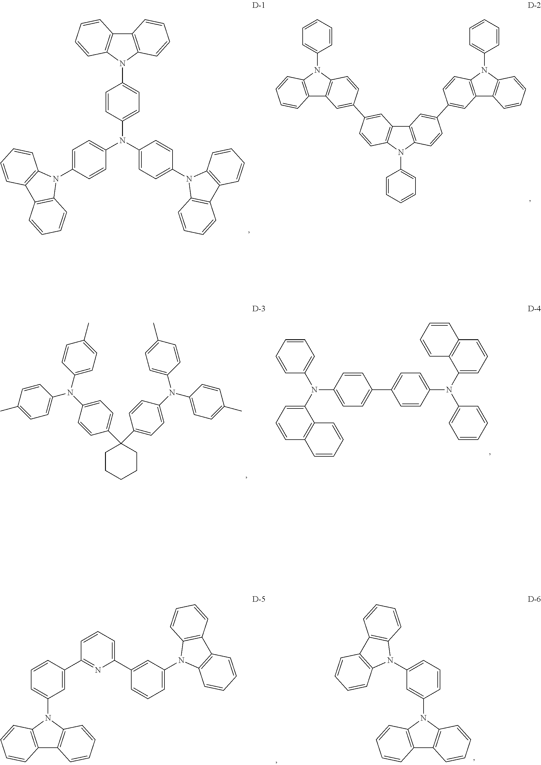
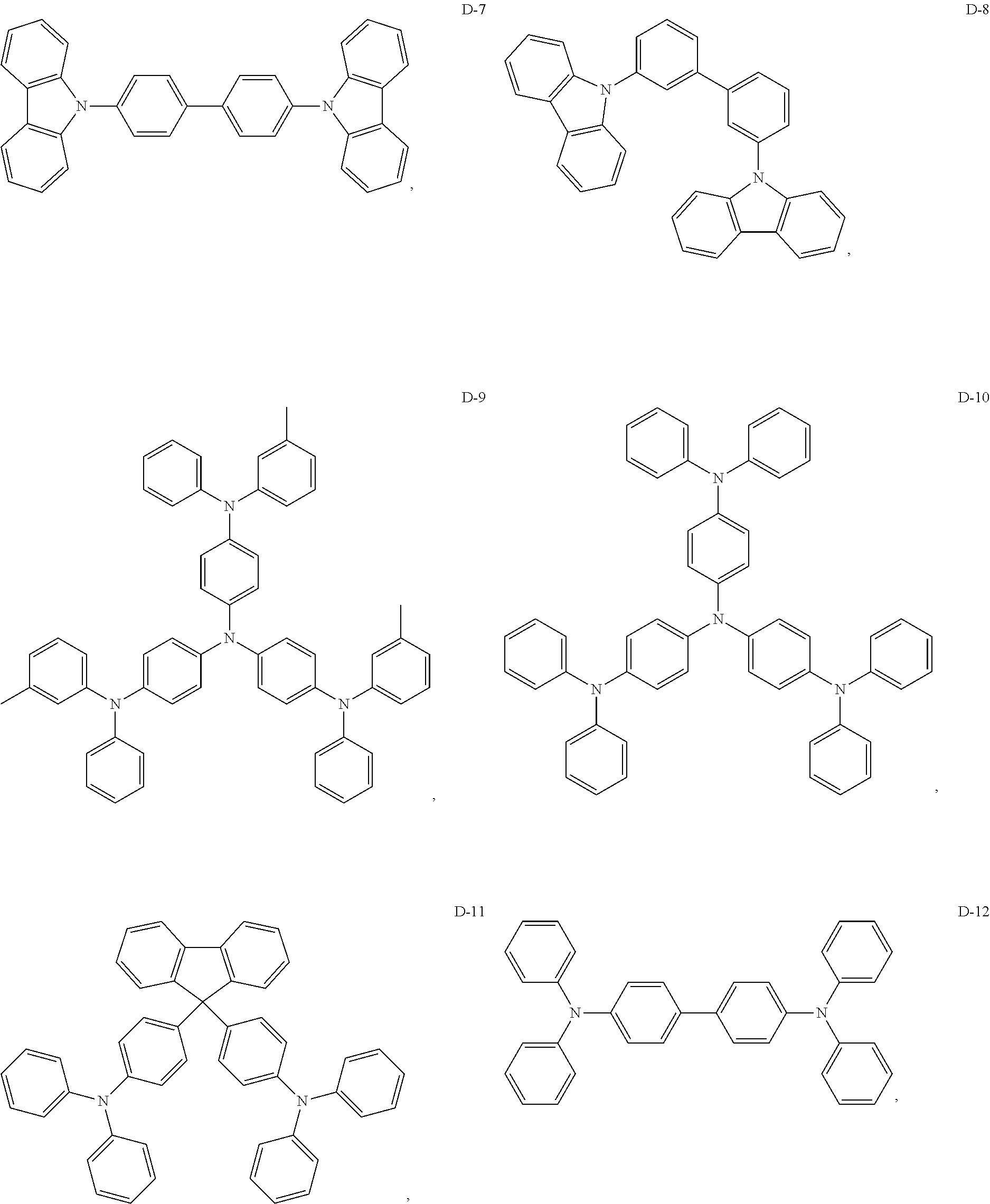
8. The organic electroluminescent device of claim 1, wherein the electron donor material is a compound containing at least one of a triphenylamine group, a diphenylamino group and a carbazolyl group.
9. The organic electroluminescent device of claim 8, wherein the electron donor material is selected from at least one of the compounds having the structures shown below: ##STR00059## ##STR00060## ##STR00061##
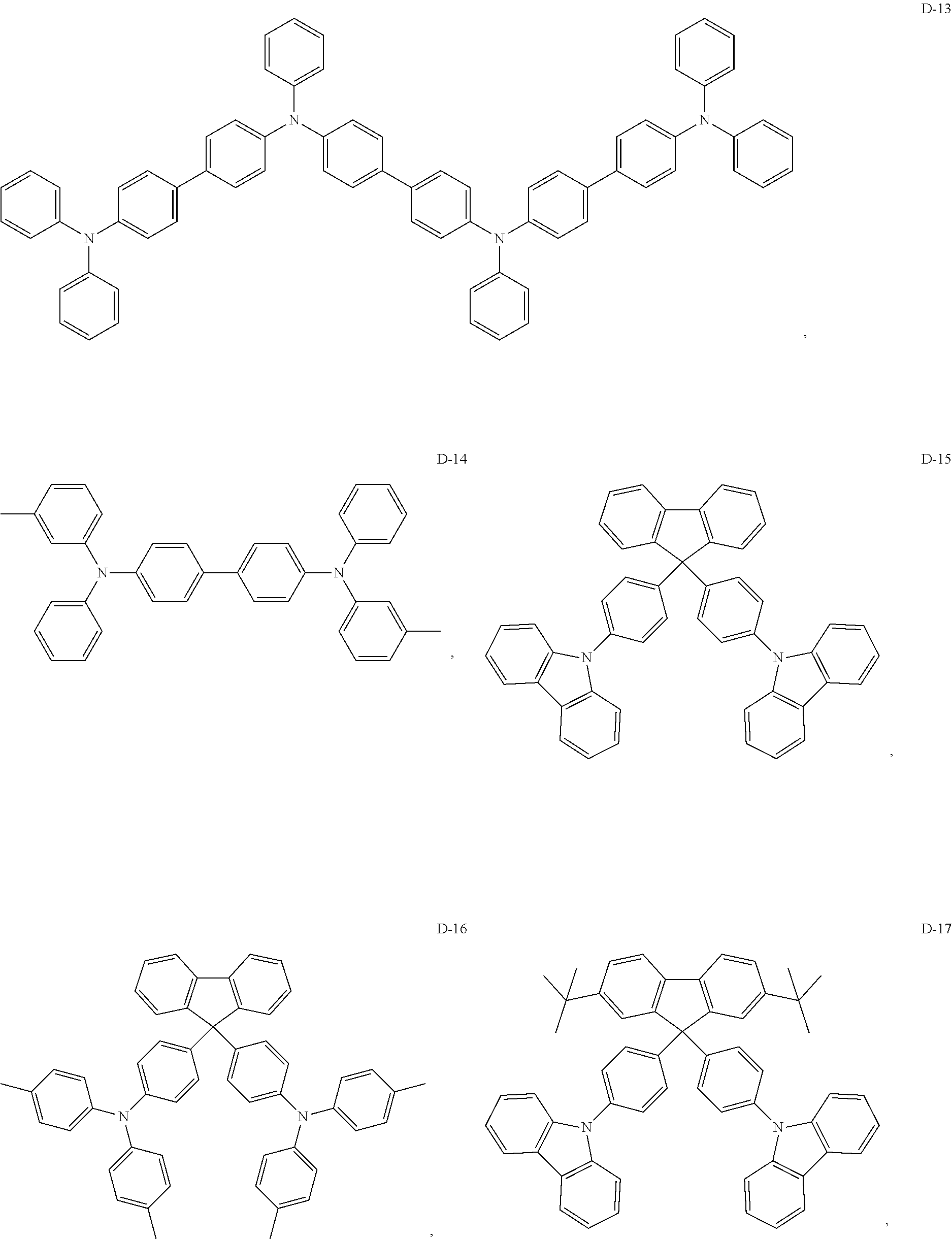
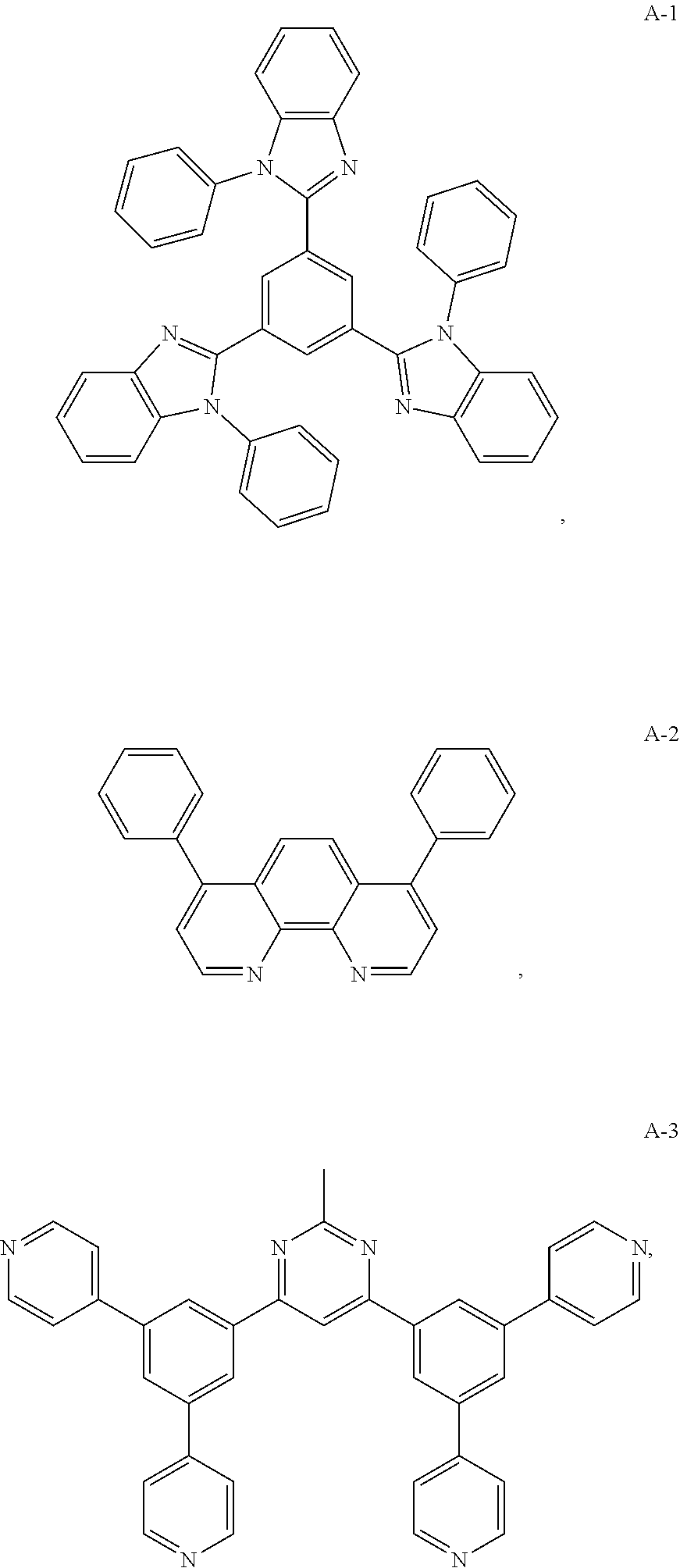
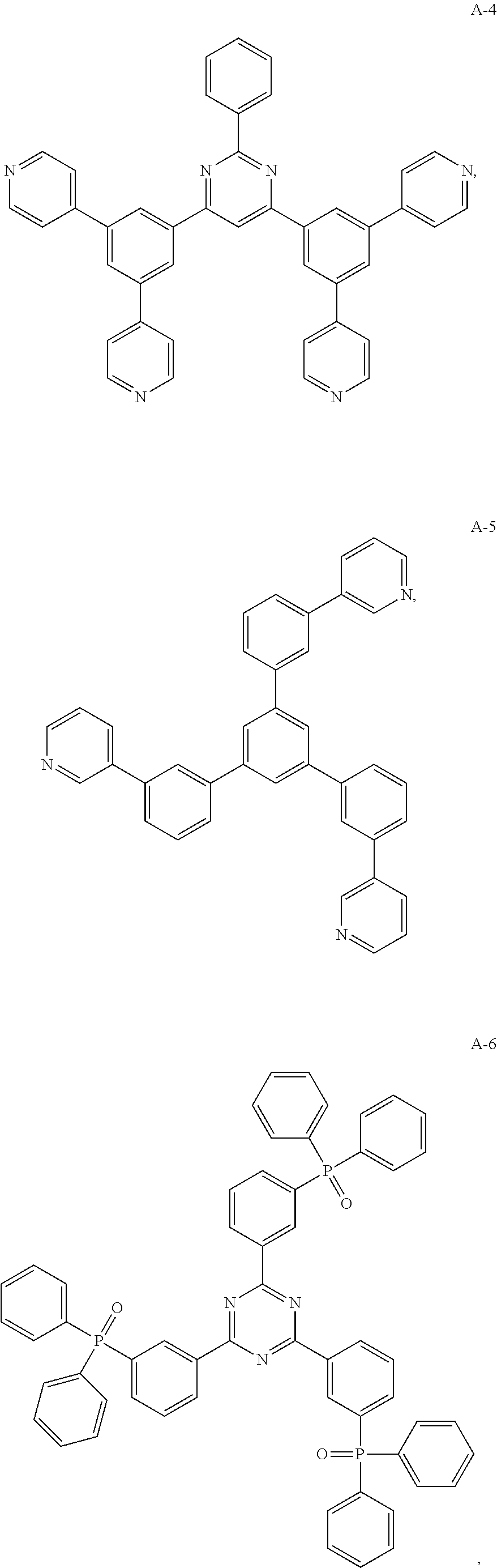
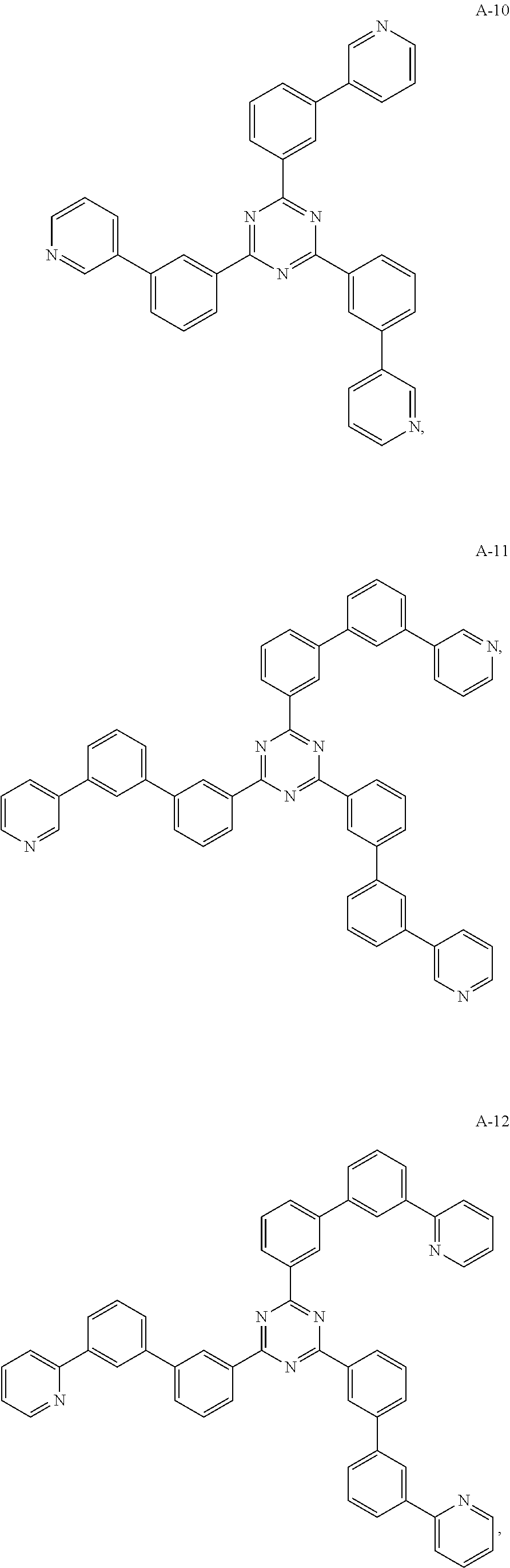
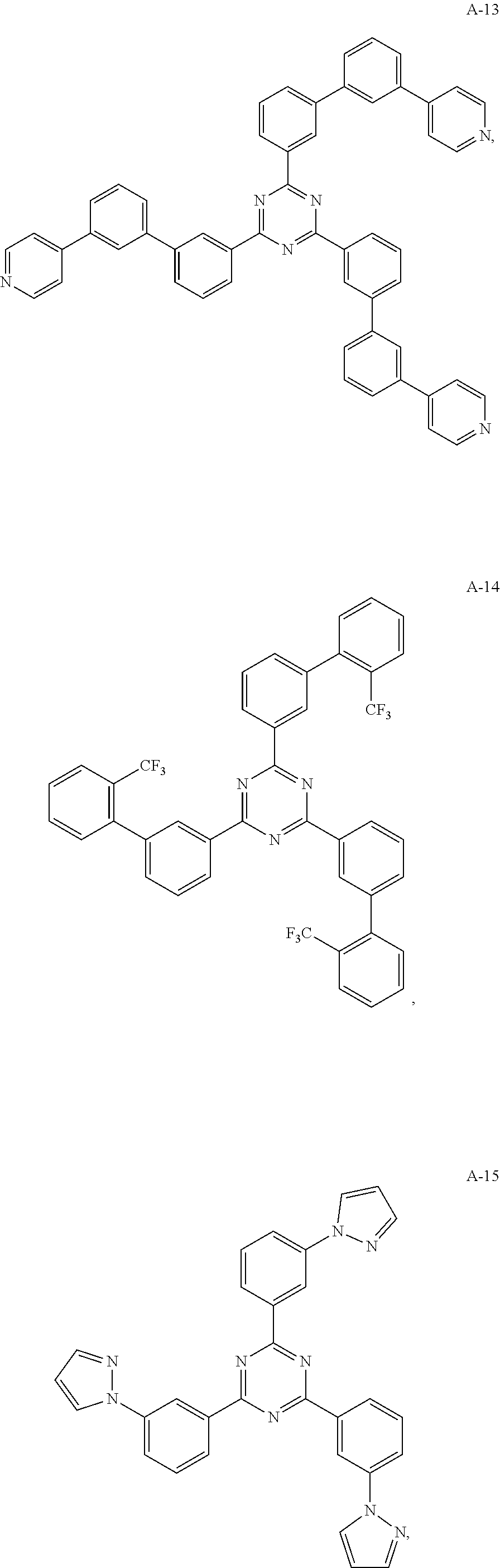
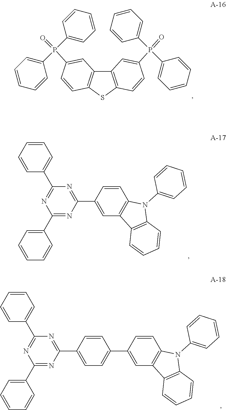
10. The organic electroluminescent device of claim 1, wherein the electron acceptor material is a compound containing at least one of a pyridyl group, a pyrimidine group, a triazine group, an imidazole group and a phenanthroline group.
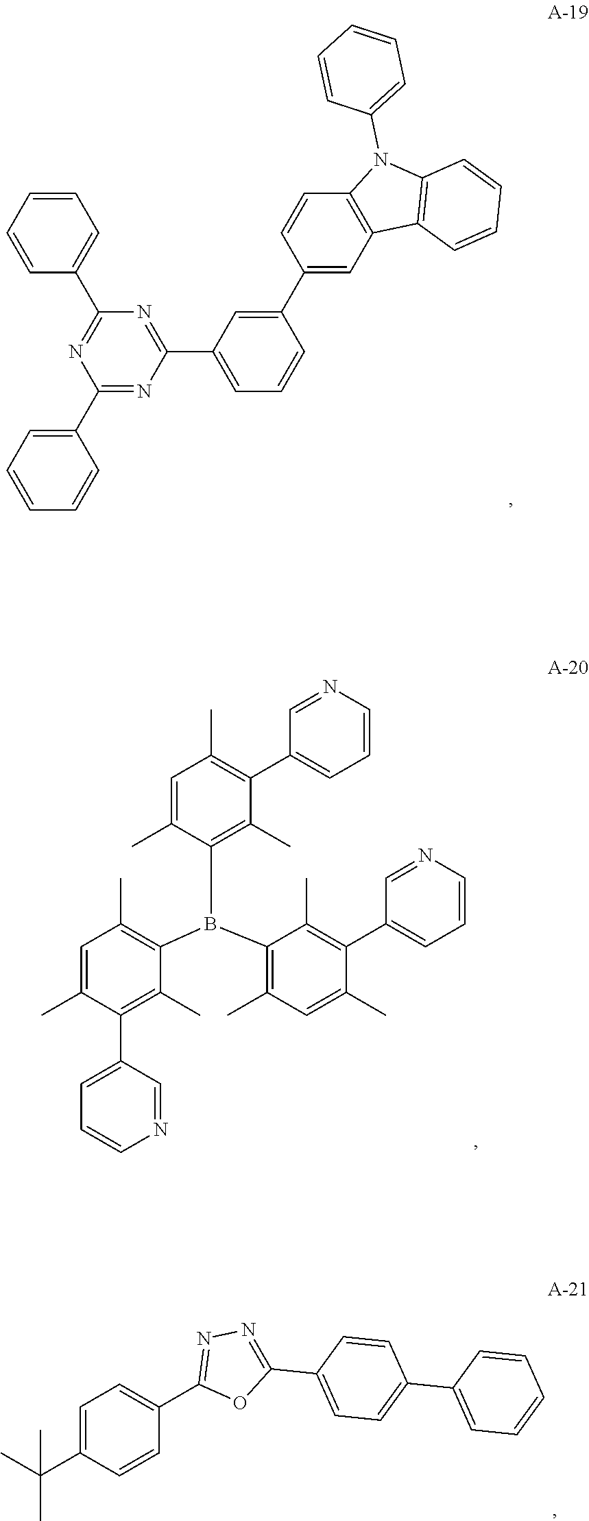
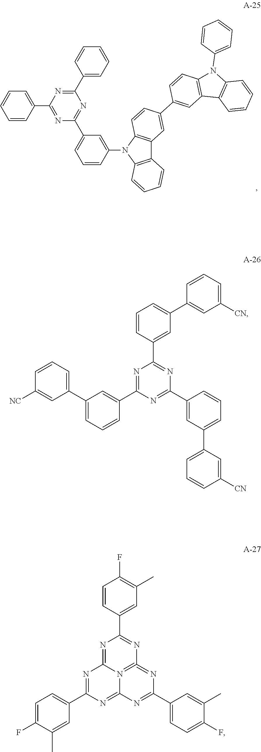
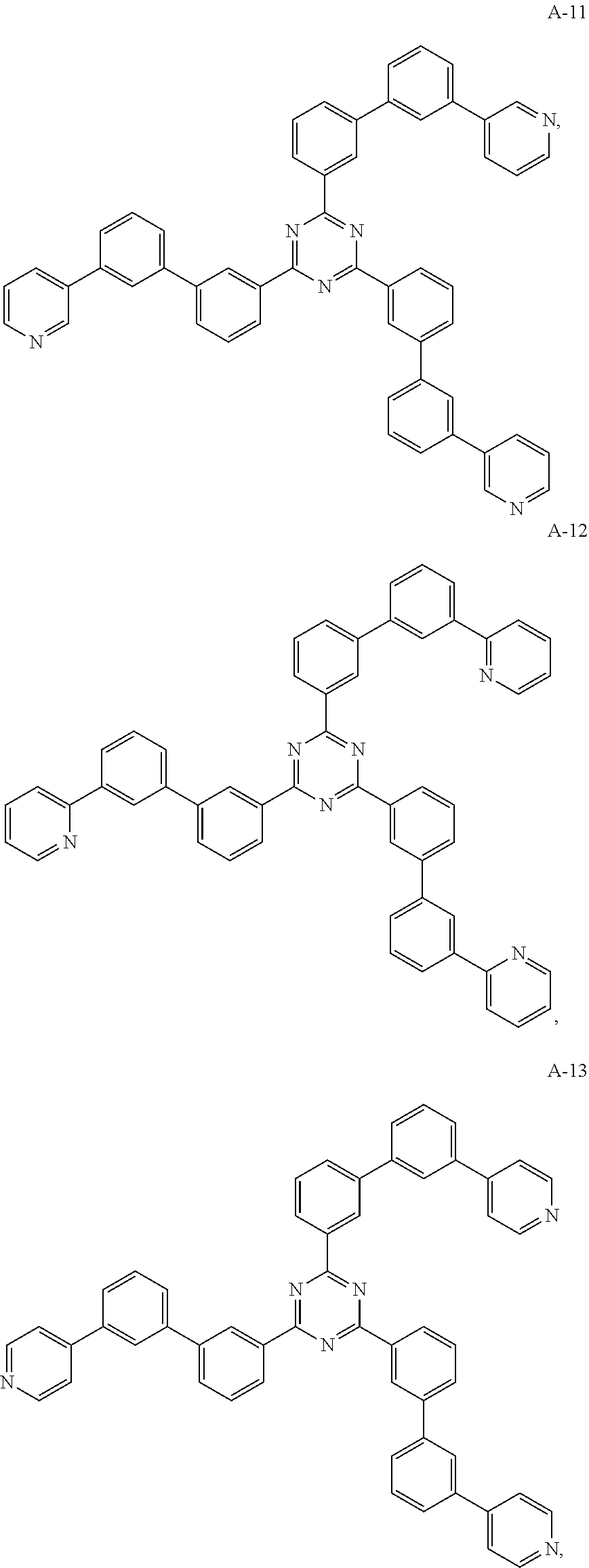
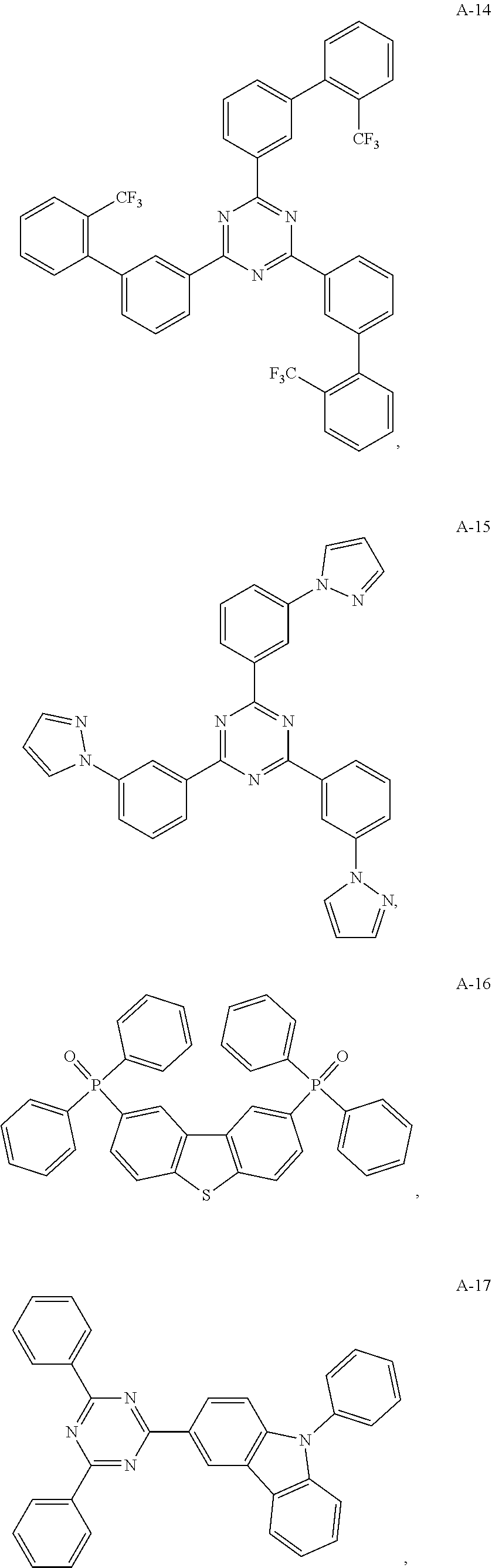
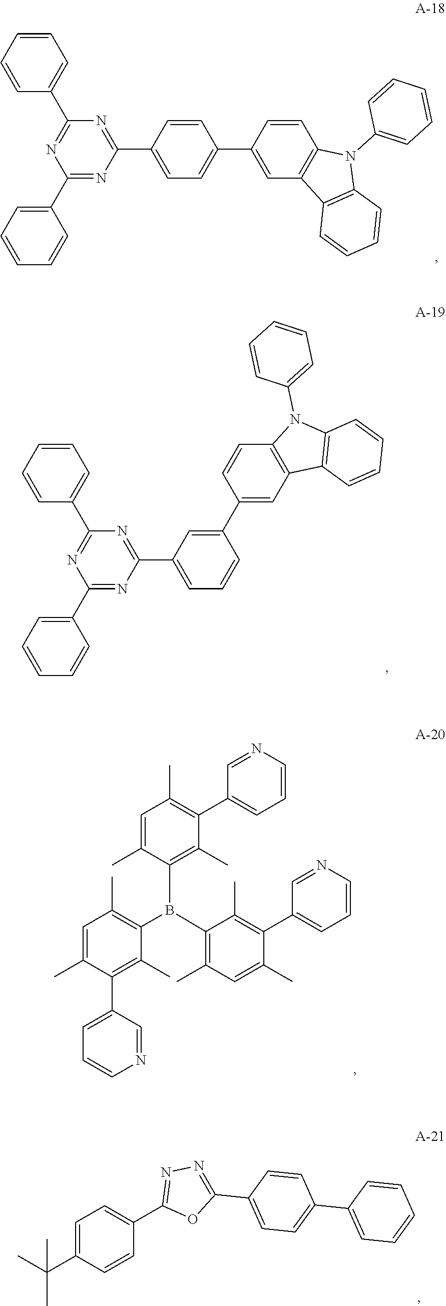
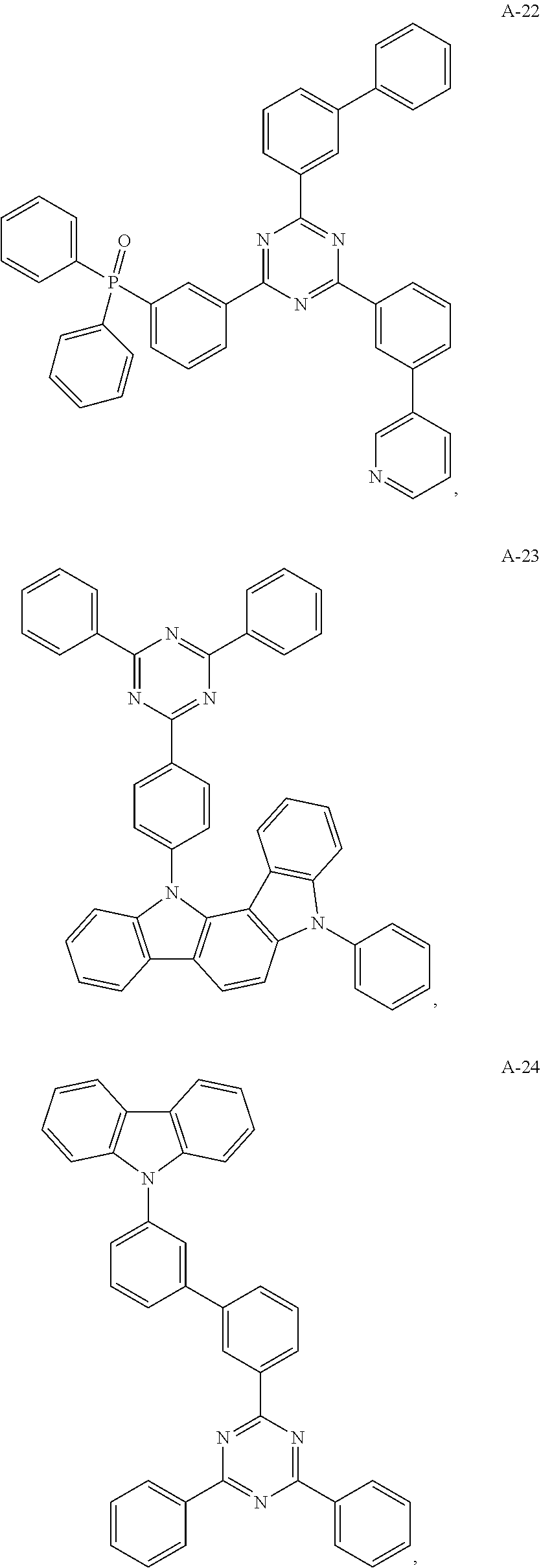
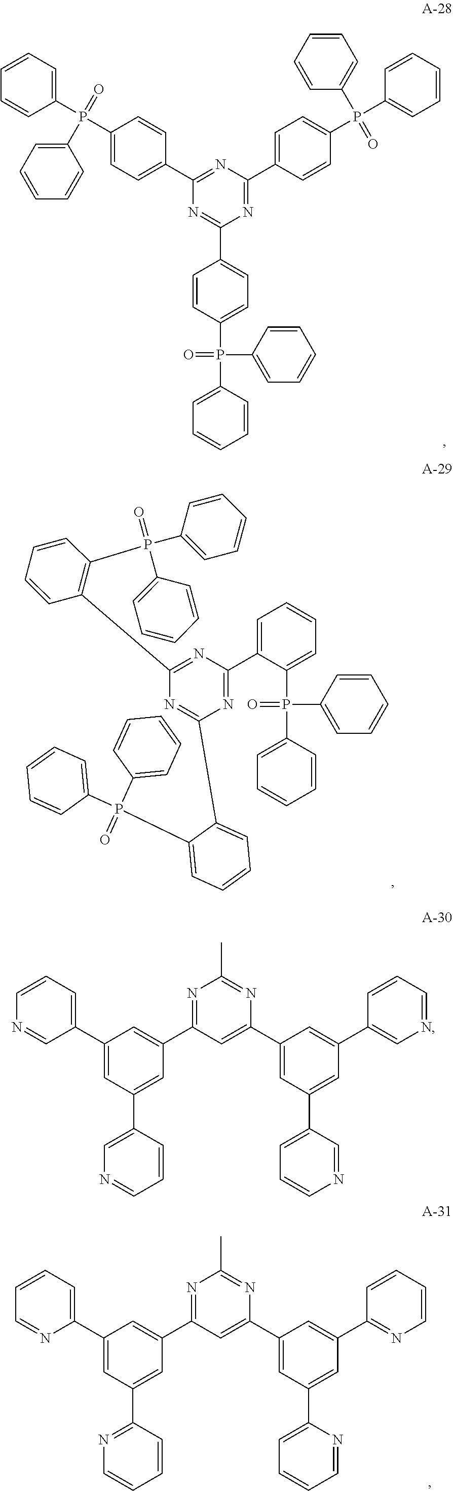
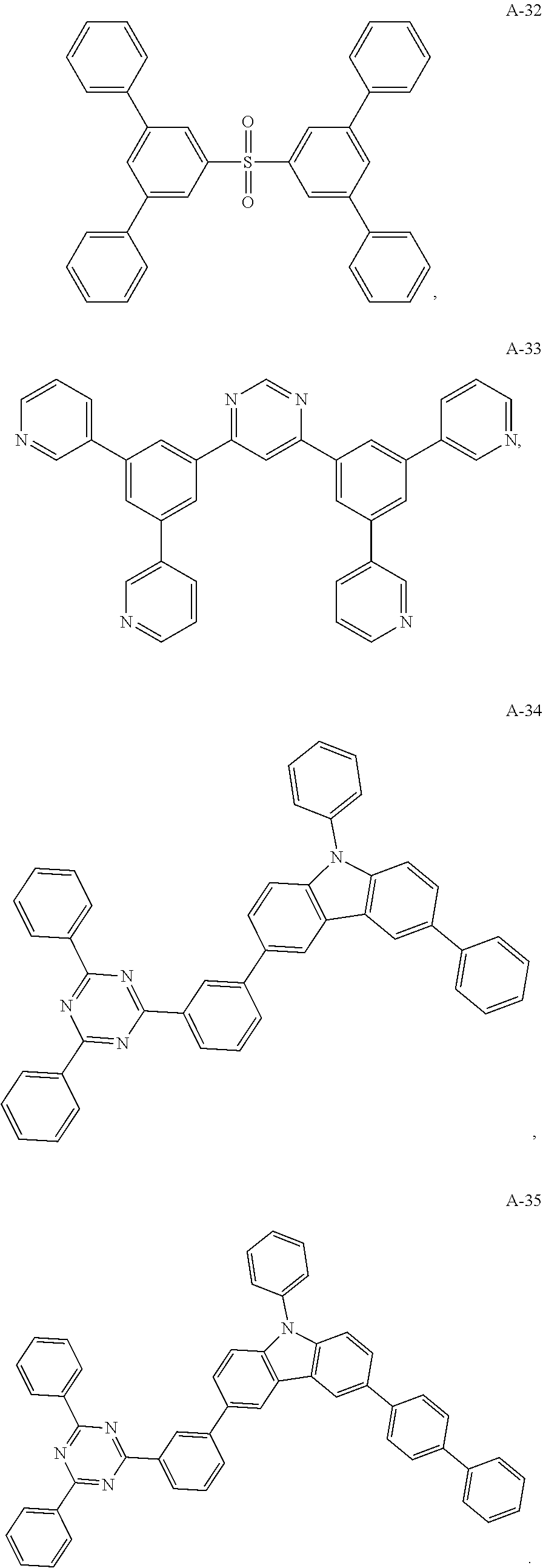
11. The organic electroluminescent device of claim 10, wherein the electron acceptor material is selected from at least one of the compounds having the structures shown below: ##STR00062## ##STR00063## ##STR00064## ##STR00065## ##STR00066## ##STR00067## ##STR00068## ##STR00069## ##STR00070## ##STR00071##
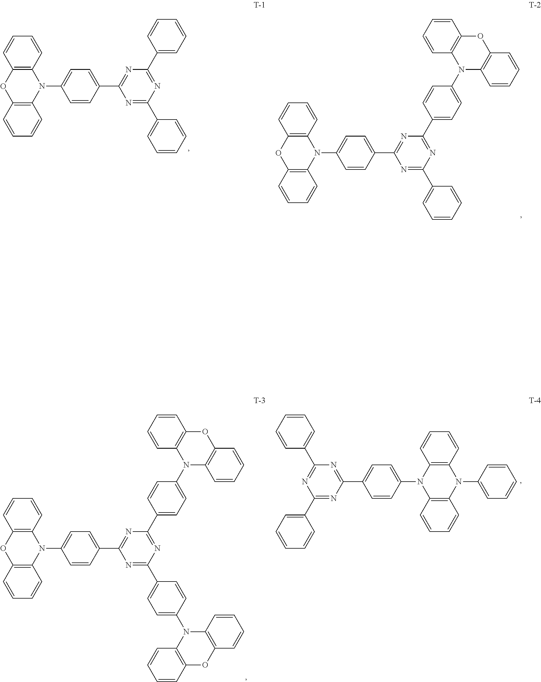
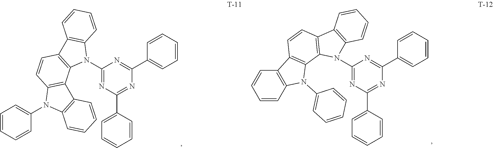
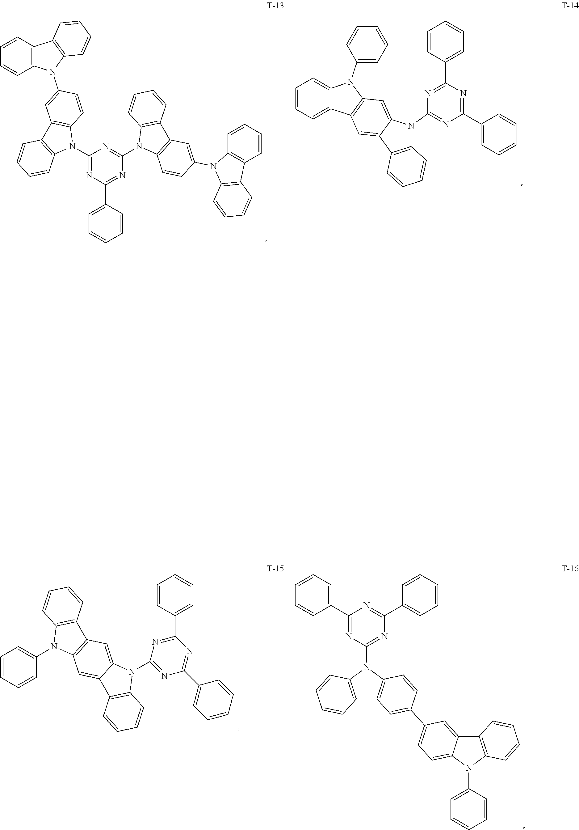
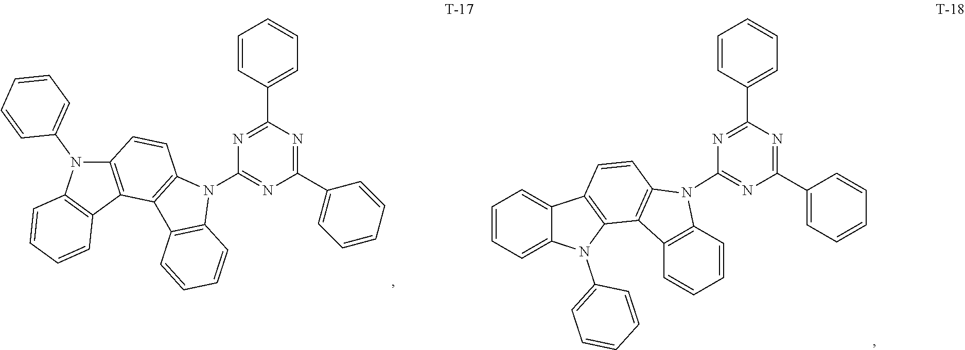
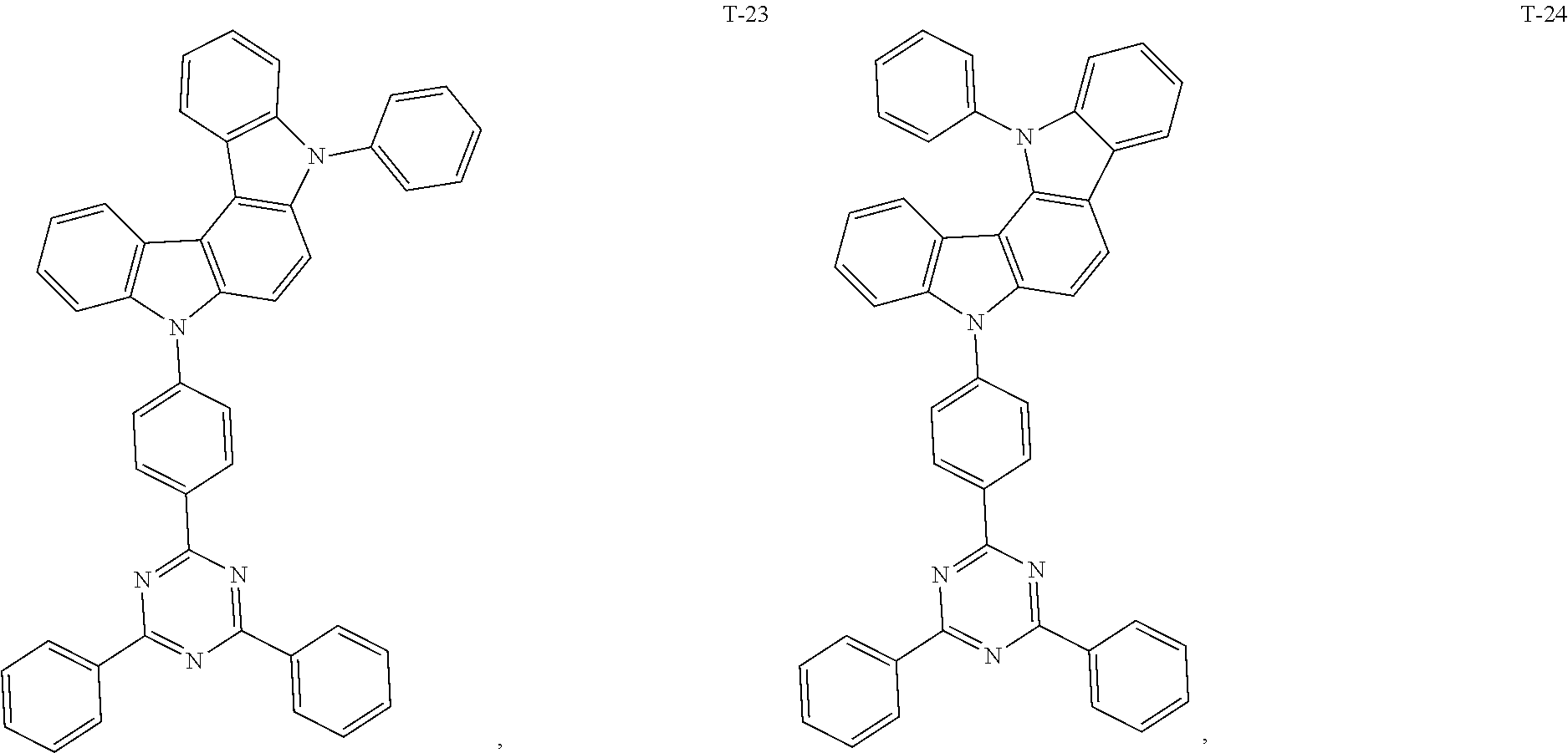
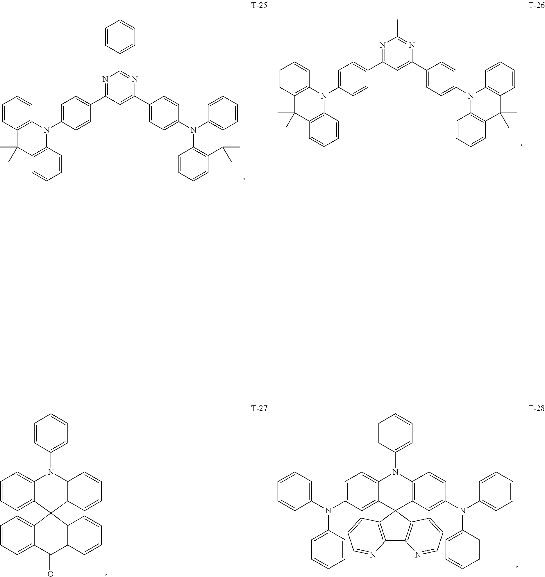
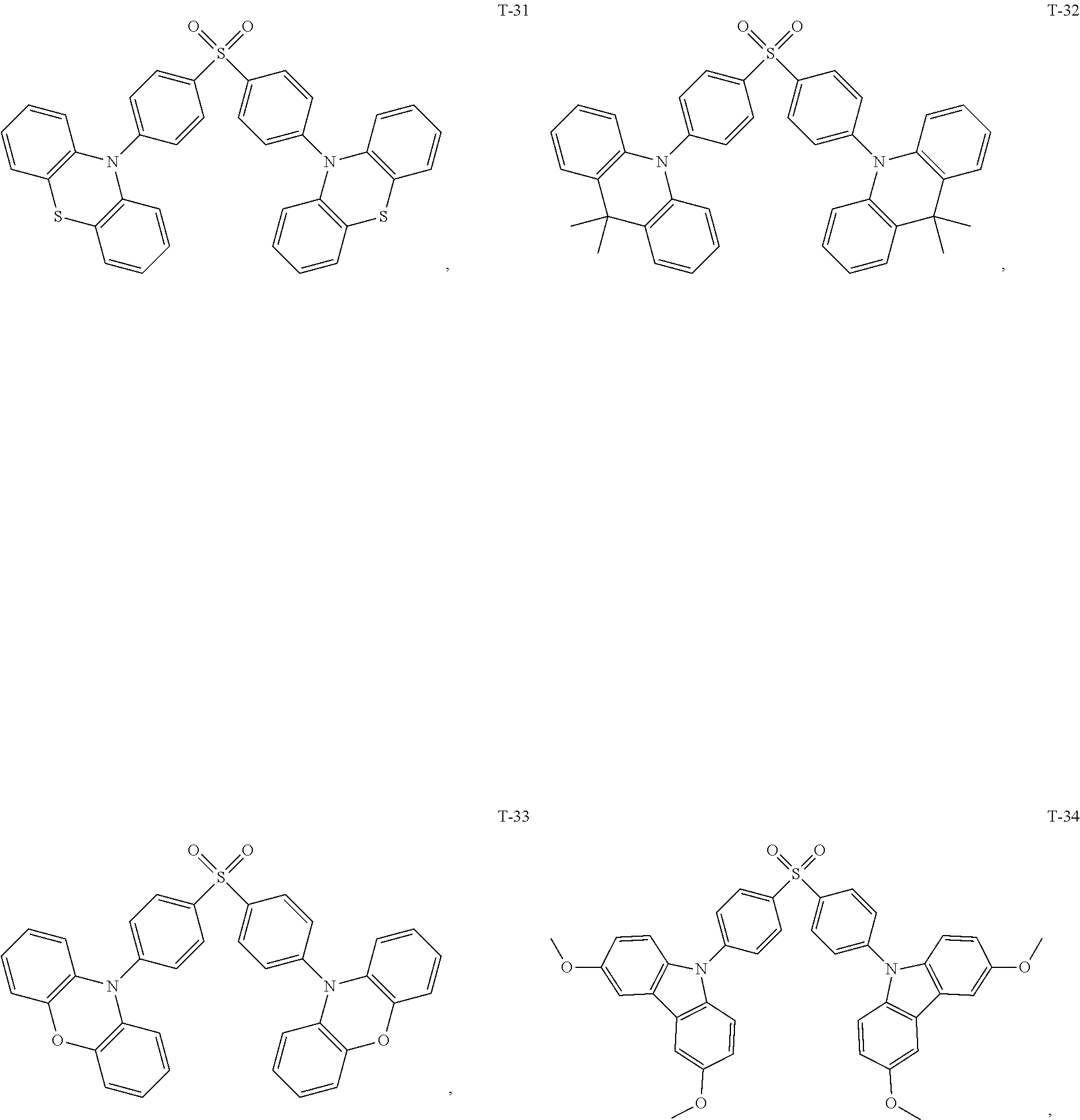
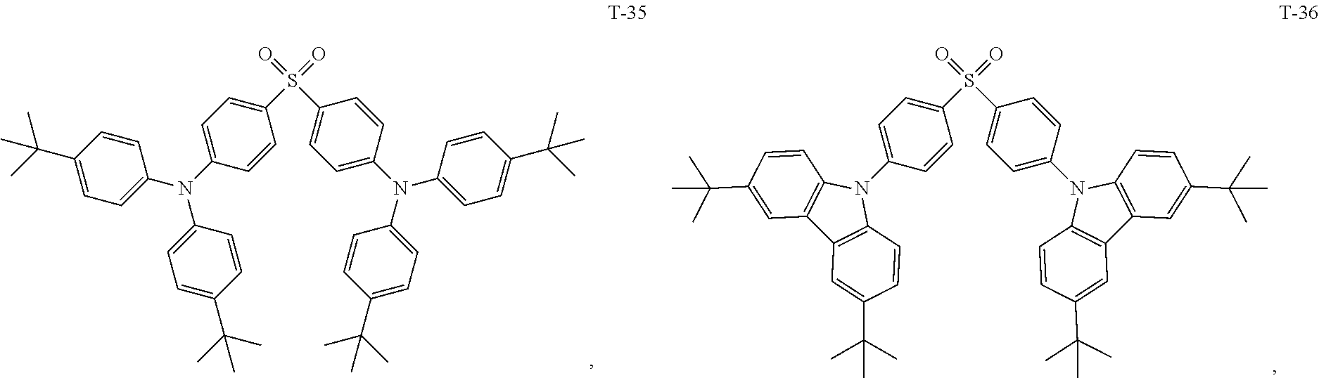
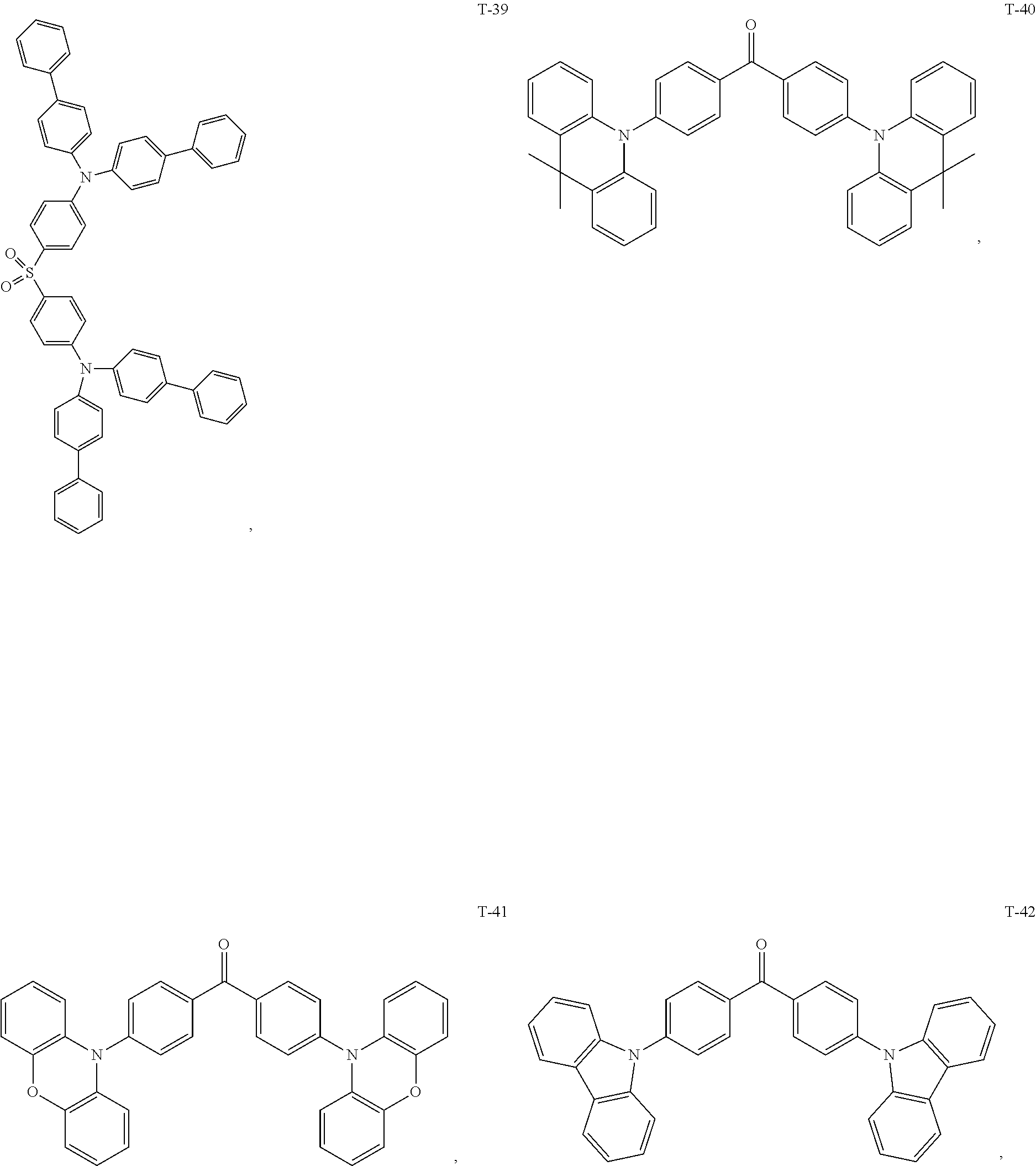
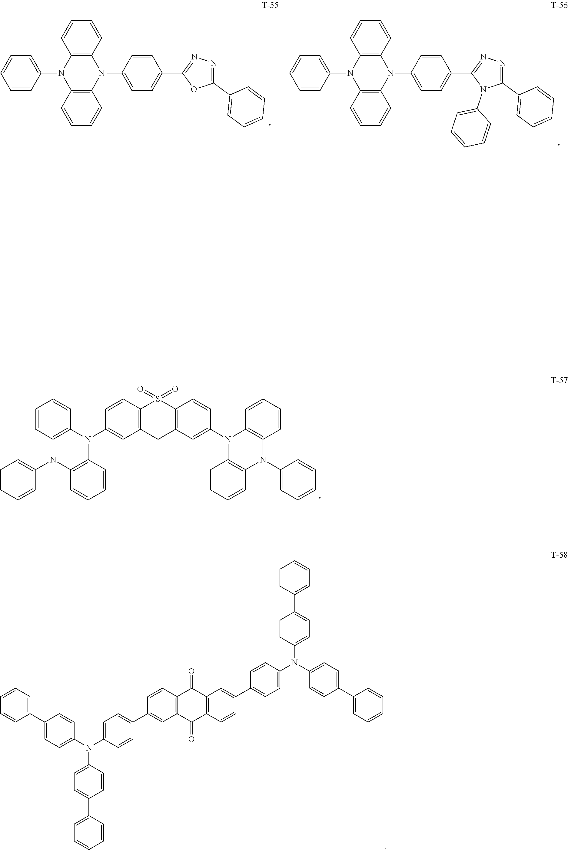
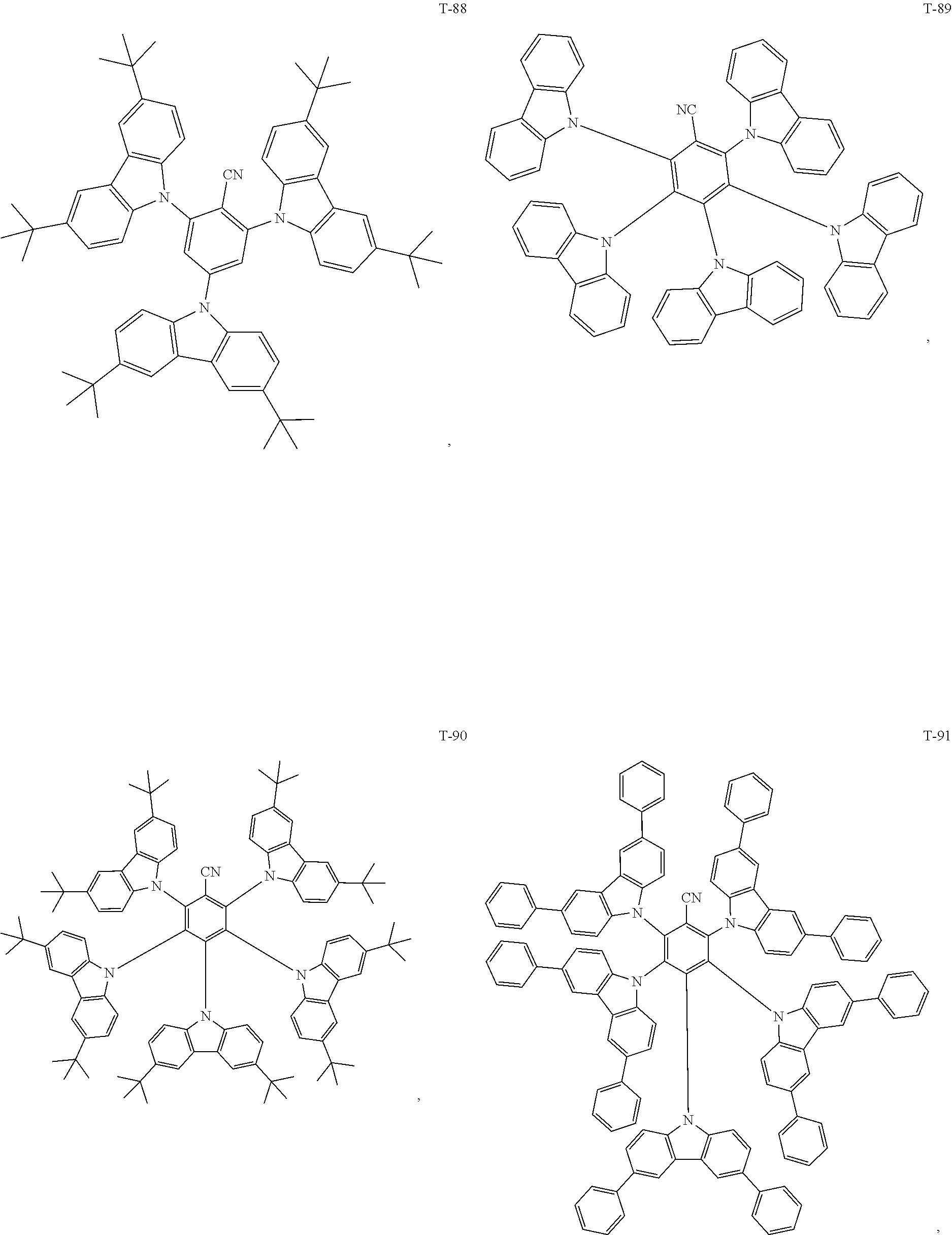
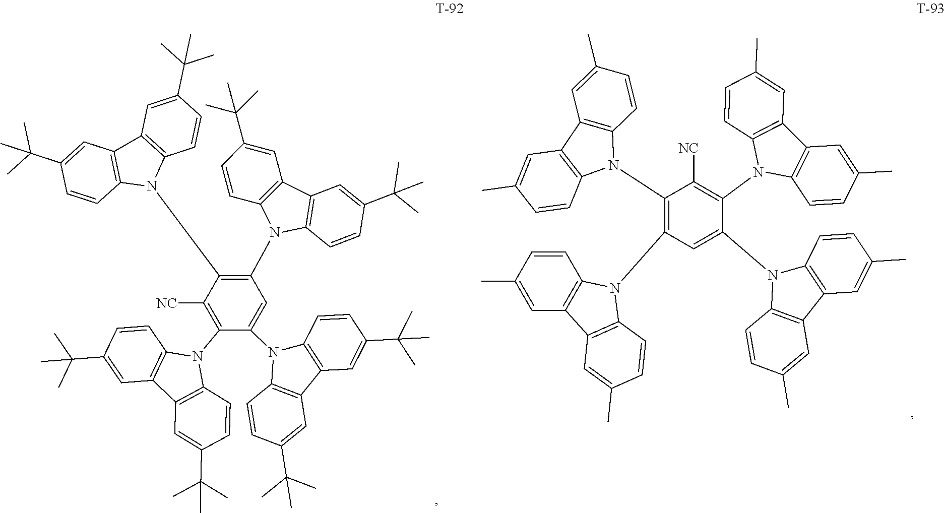
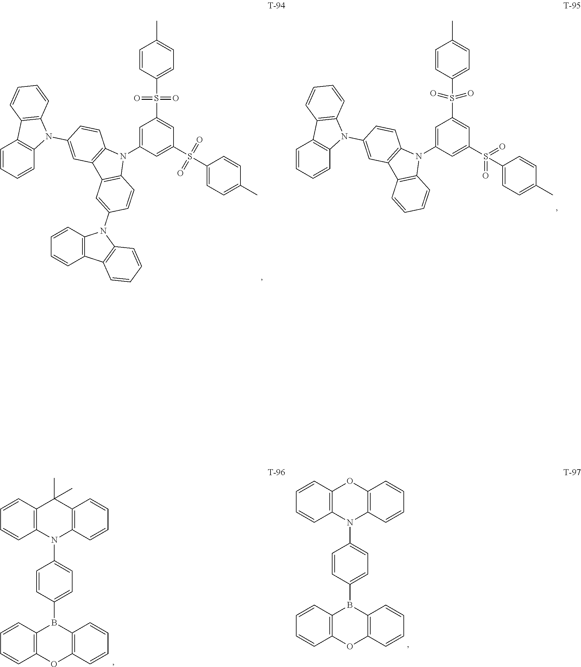
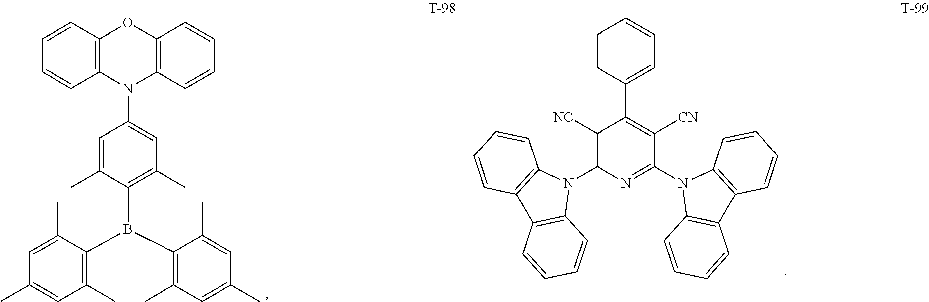
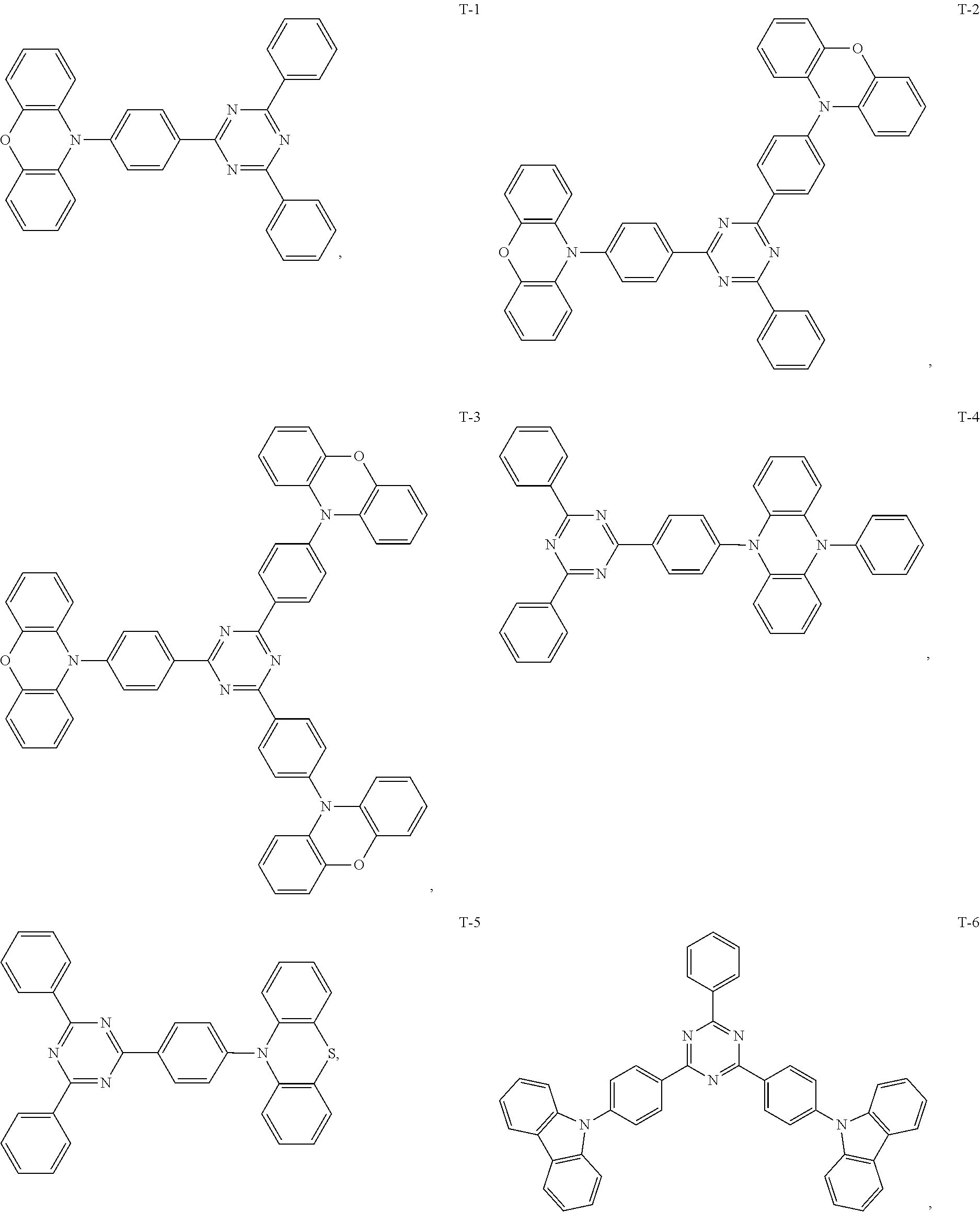
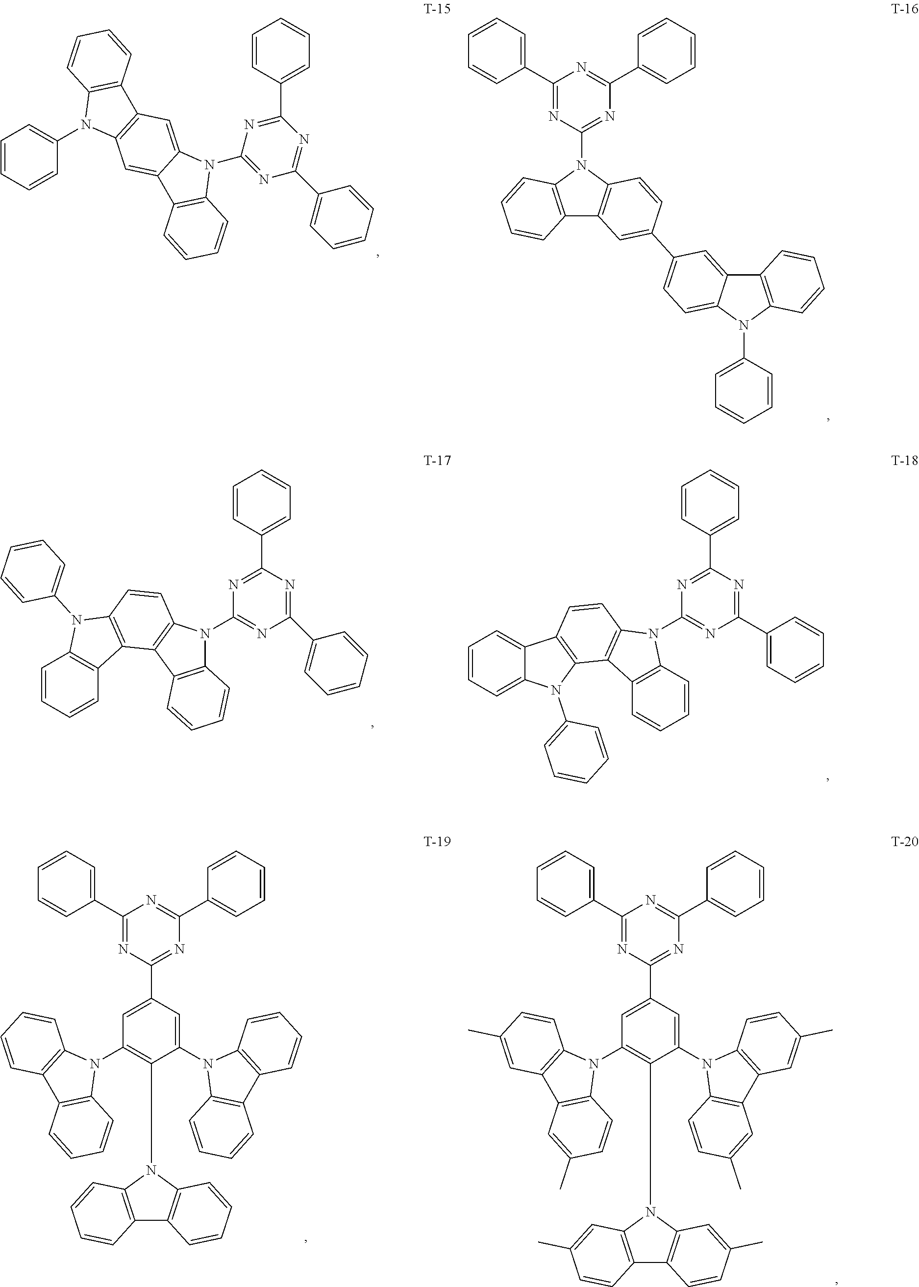
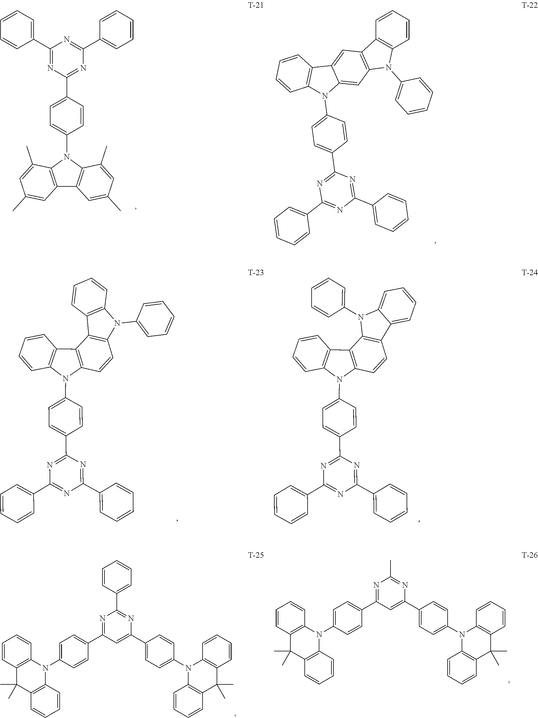
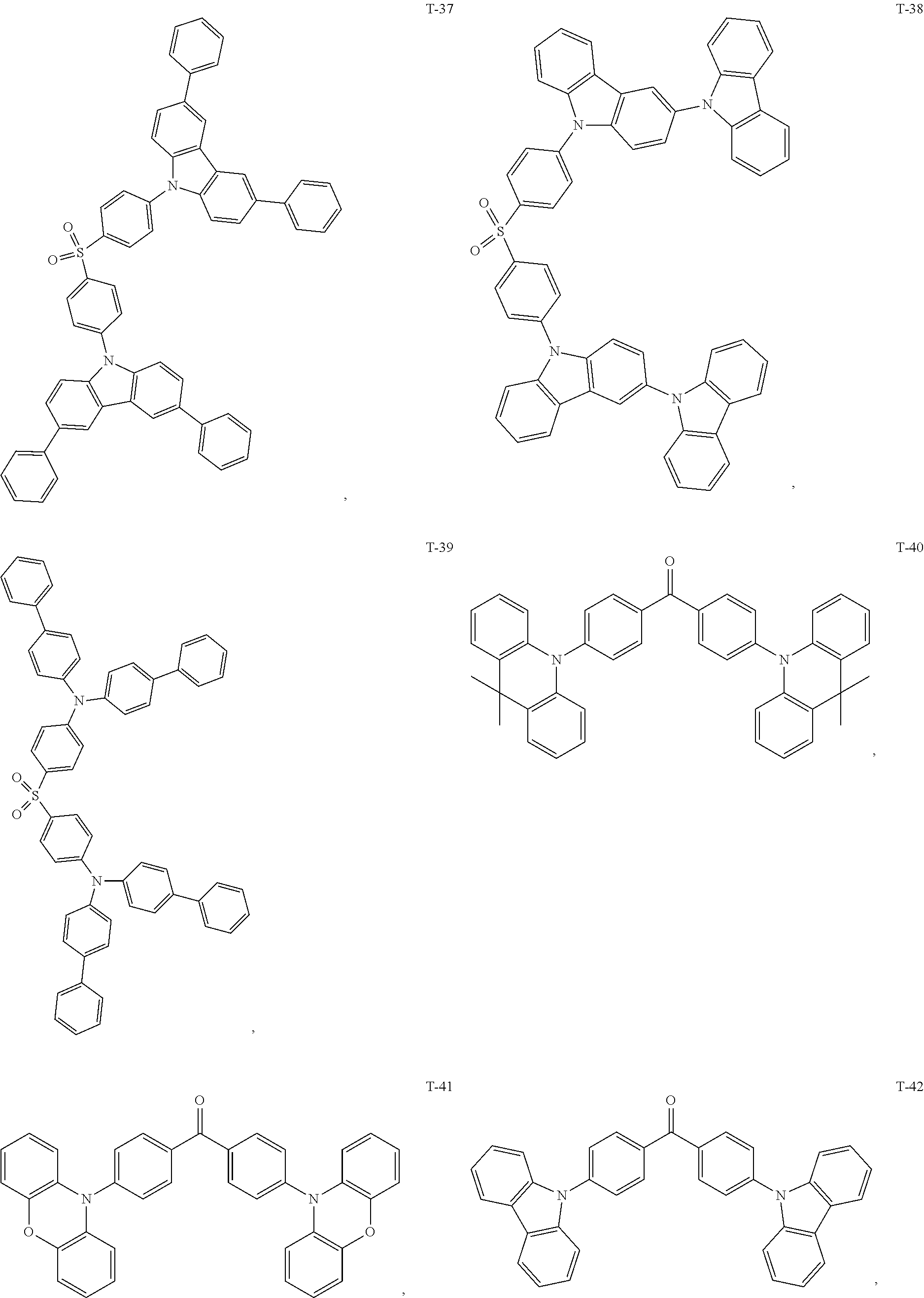
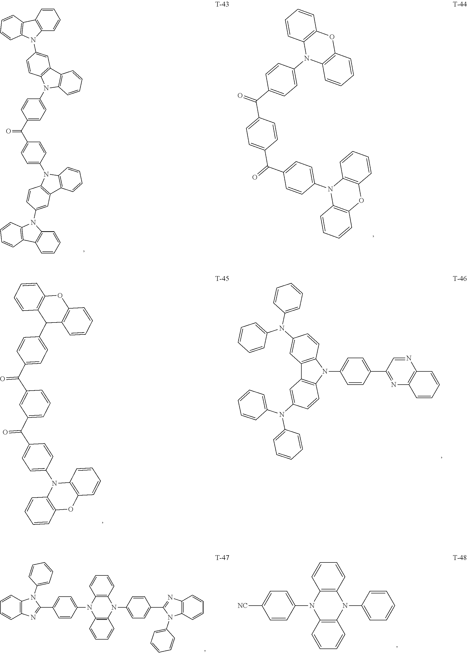
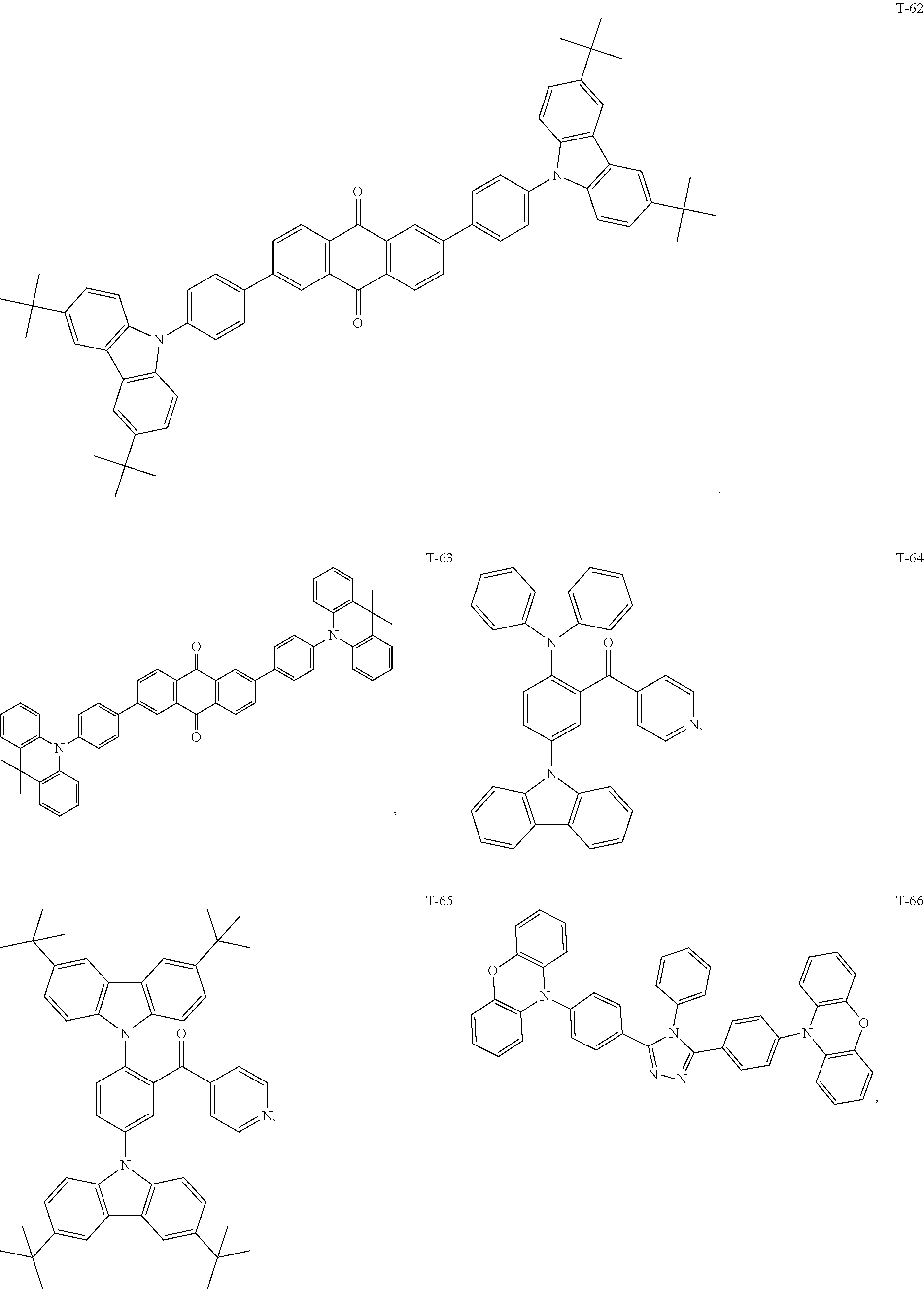
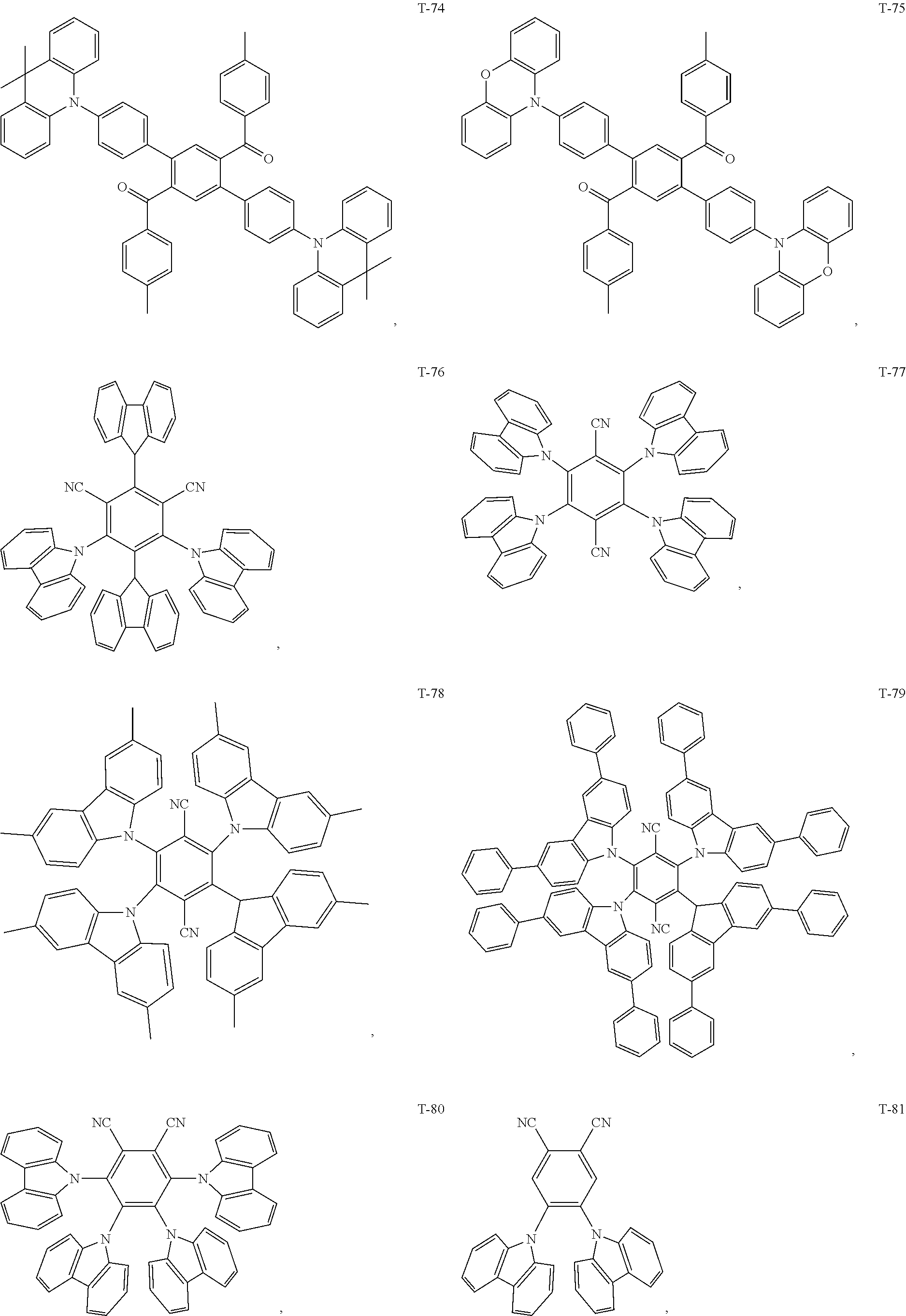
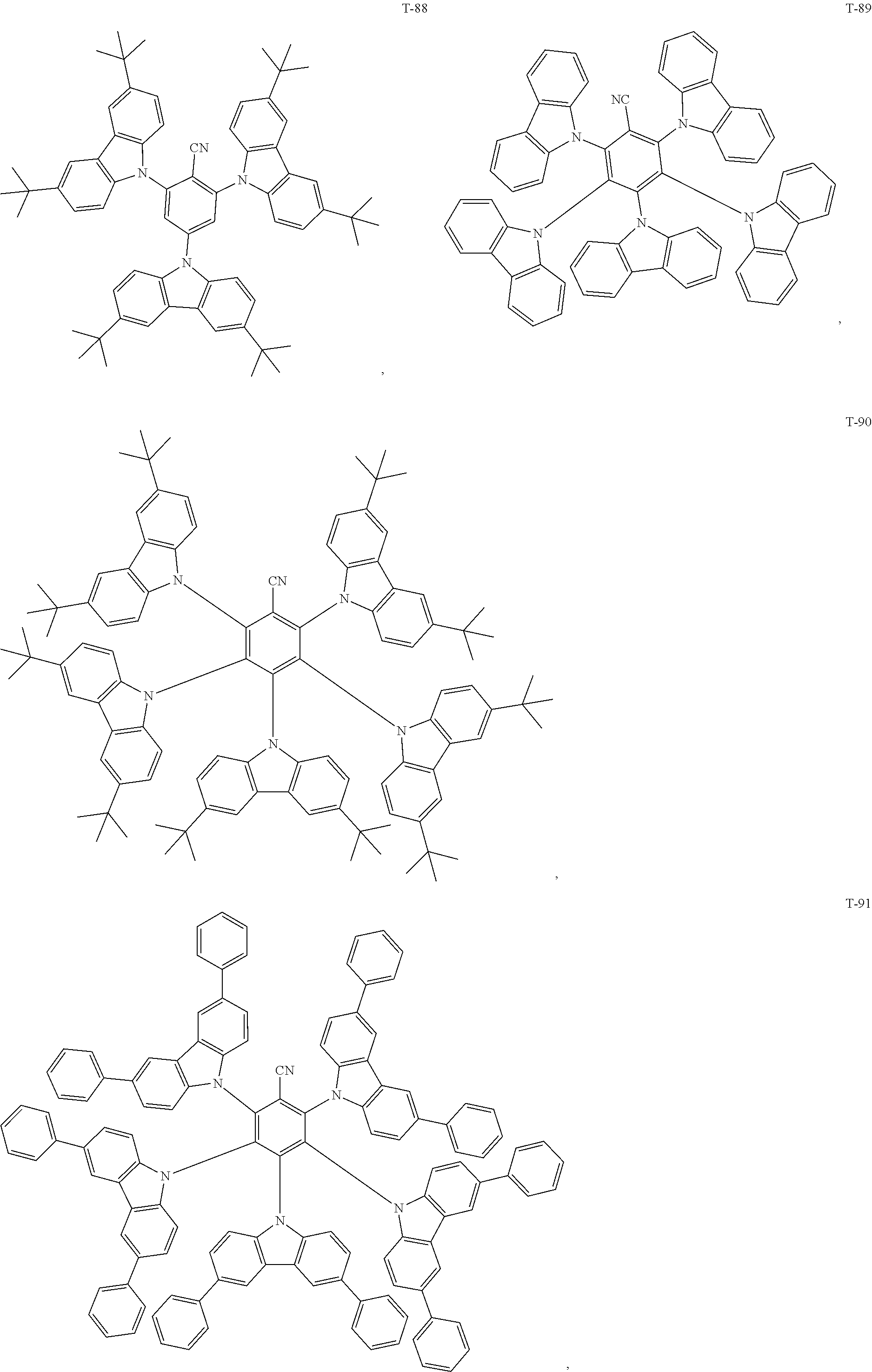
12. The organic electroluminescent device of claim 1, wherein the thermally activated delayed fluorescence material is selected from at least one of compounds of structures shown below: ##STR00072## ##STR00073## ##STR00074## ##STR00075## ##STR00076## ##STR00077## ##STR00078## ##STR00079## ##STR00080## ##STR00081## ##STR00082## ##STR00083## ##STR00084## ##STR00085## ##STR00086## ##STR00087##
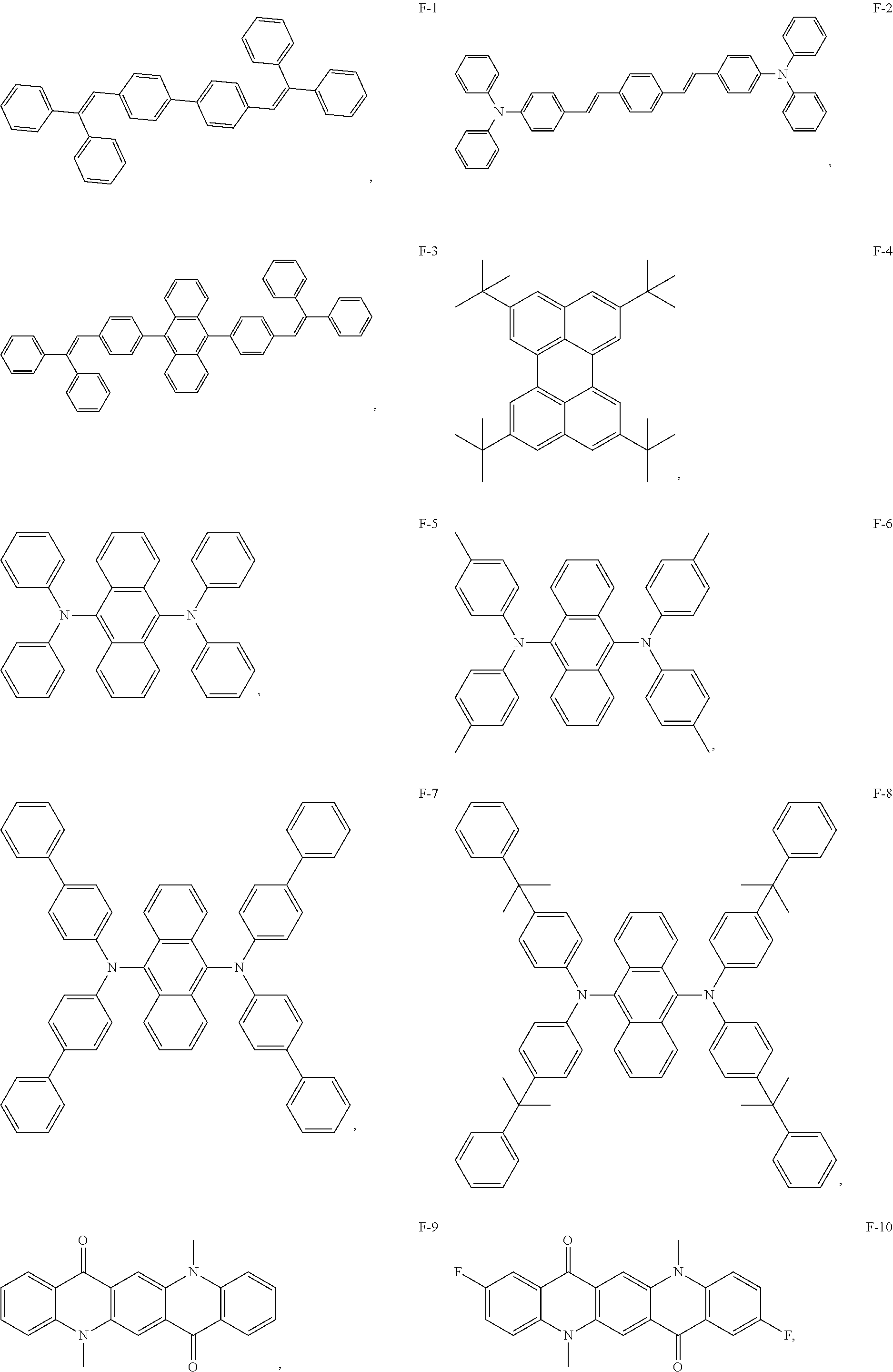
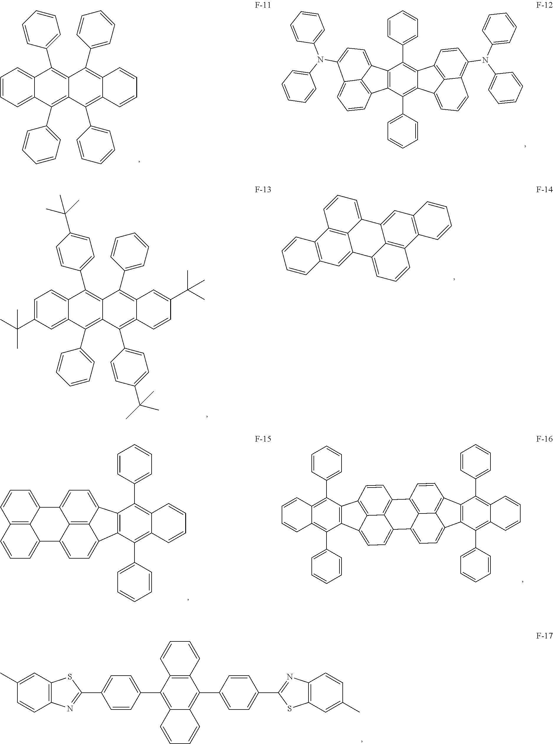
13. The organic electroluminescent device of claim 1, wherein the fluorescent dye is selected from at least one of compounds of structures shown below: ##STR00088## ##STR00089## ##STR00090##
14. A method for preparing an organic electroluminescent device, comprising: sequentially preparing an anode, a hole transport layer, a light-emitting layer, an electron transport layer and a cathode on a substrate; wherein the light-emitting layer is prepared by simultaneously evaporating an electron donor material, an electron acceptor material, an auxiliary host material with thermally activated delayed fluorescence characteristics and a fluorescent dye in different evaporation sources respectively; or the light-emitting layer layer is prepared by pre-mixing the electron donor material and the electron acceptor material in a same evaporation source, and then simultaneously evaporating the pre-mixed electron donor material and electron acceptor material, the auxiliary host material with thermally activated delayed fluorescence characteristics and the fluorescent dye in different evaporation sources respectively.
15. The method of claim 14, wherein when the electron donor material and the electron acceptor material are evaporated in the same evaporation source, an absolute value of molar mass difference between the electron donor material and the electron acceptor material is less than 100 g/mol, and an absolute value of temperature difference of sublimation temperatures between the electron donor material and the electron acceptor material is less than or equal to 20.degree. C.
Description
CROSS-REFERENCES TO RELATED APPLICATIONS
[0001] This application is a continuation application for International Application PCT/CN2018/089396, filed on May 31, 2018, which claims the priority benefit of Chinese Patent Application No. 201711479570.3, titled "ORGANIC ELECTROLUMINESCENT DEVICES AND PREPARATION METHODS THEREOF" and filed on Dec. 29, 2017. The entireties of both applications are incorporated by reference herein for all purposes.
TECHNICAL FIELD
[0002] The present disclosure relates to display technologies.
BACKGROUND
[0003] As a new type of flat panel display technology, organic light emitting diode (OLED) devices have a sandwich structure. That is, an organic light-emitting layer is sandwiched between the electrodes on both sides. The holes and the electrons are injected from the anode and the cathode, respectively, and transported in the organic light-emitting layer, then combine to form excitons after encounter. The excitons return to the ground state and emit light by radiative transition of the fluorescent or phosphorescent process. Due to its advantages such as wide viewing angle, ultra-thin, fast response, high luminous efficiency, and flexible display etc., OLED has great application prospects in the field of display and illumination, and has attracted more and more attention.
[0004] Under electrical excitation, excitons are generally composed of 25% singlet excitons and 75% triplet excitons. For fluorescent dyes, only 25% of singlet excitons can be utilized due to electron spin inhibition, the remaining 75% of the triplet excitons are lost due to the non-radiative transition, therefore the internal quantum efficiency of the organic electroluminescent device of the general fluorescent material does not exceed 25%. In 2012, Adachi et al. of Kyushu University in Japan reported on the highly efficient and metal-free Thermally Activated Delayed Fluorescence (TADF) materials and devices in Nature.
SUMMARY
[0005] Therefore, the technical problem to be solved by the present disclosure is to overcome the high driving voltage caused by the wide band gap of the host material and low exciton utilization efficiency caused by the Dexter energy transfer from the host material molecules to the luminescent dye molecules of the organic electroluminescent device in the prior art.
[0006] To this end, the present disclosure provides an organic electroluminescent device including a light-emitting layer, the material of the light-emitting layer includes a host material, an auxiliary host material and a fluorescent dye;
[0007] the host material is an exciplex prepared by mixing an electron donor material and an electron acceptor material, the auxiliary host material is a thermally activated delayed fluorescence material, and a triplet energy level of the exciplex is higher than a singlet energy level of the auxiliary host material.
[0008] Optionally, in the organic electroluminescent device, a triplet energy level of the auxiliary host material is higher than a singlet energy level of the fluorescent dye.
[0009] Optionally, in the organic electroluminescent device, a triplet energy level of the electron donor material and a triplet energy level of the electron acceptor material are respectively higher than a triplet energy level of the host material.
[0010] Optionally, in the organic electroluminescent device, a mass ratio of the electron donor material to the electron acceptor material is 1:9 to 9:1.
[0011] Optionally, in the organic electroluminescent device, a doping ratio of the auxiliary host material (the ratio of the mass of the auxiliary host material to the total mass of the light-emitting layer) is 5 wt % to 80 wt %, and a doping ratio of the fluorescent dye (the ratio of the mass of the fluorescent dye to the total mass of the light-emitting layer) is 0.1 wt % to 10 wt %.
[0012] Optionally, in the organic electroluminescent device, the energy level difference between a singlet energy level and a triplet energy level of the host material is less than 0.15 eV.
[0013] Optionally, in the organic electroluminescent device, the energy level difference between a singlet energy level and a triplet energy level of the auxiliary host material is less than 0.3 eV.
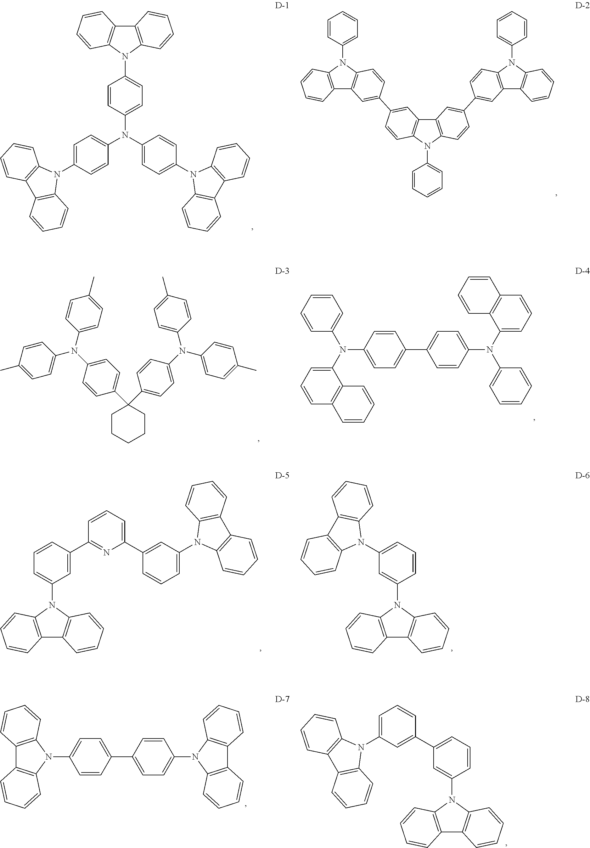
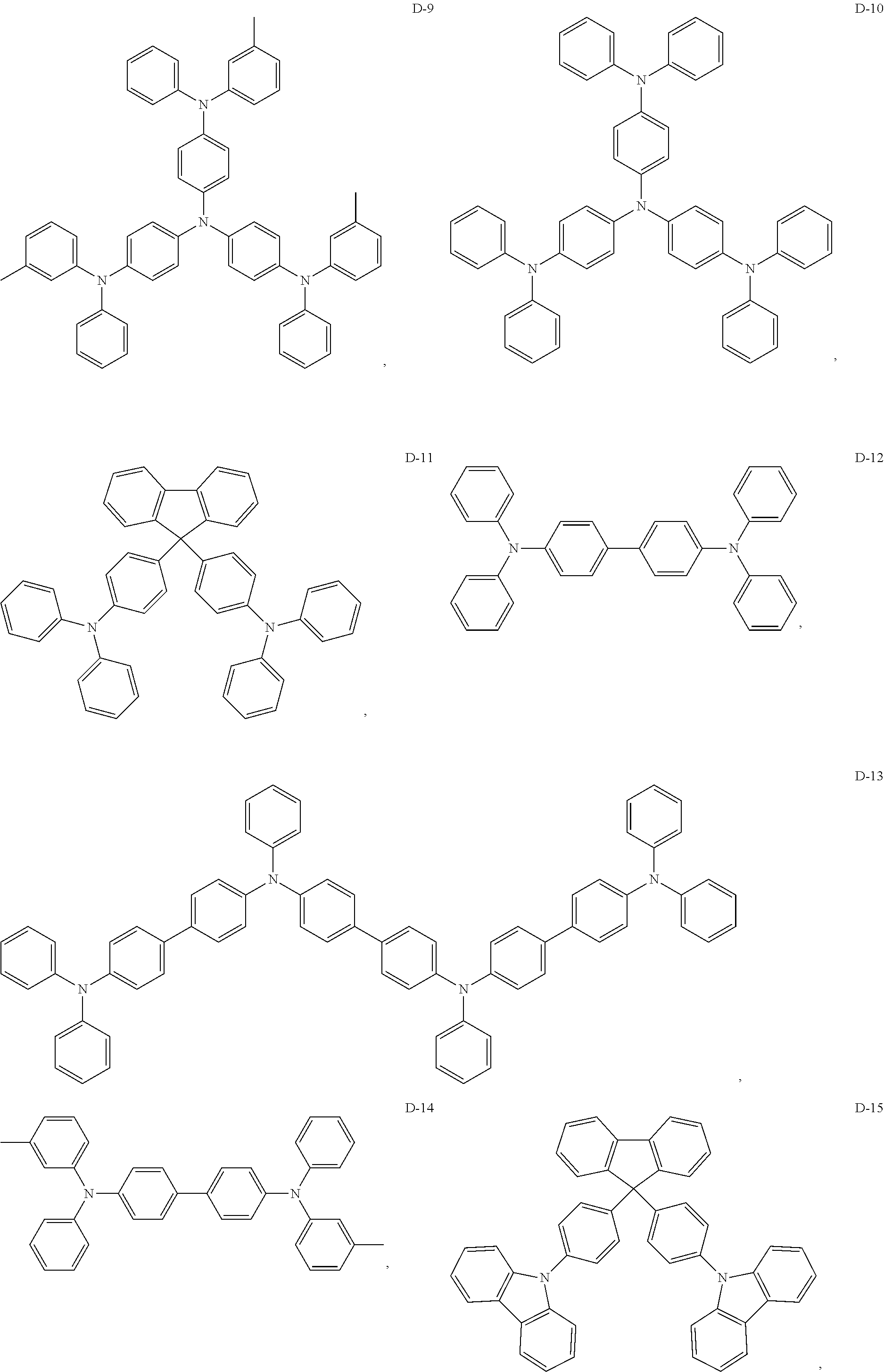
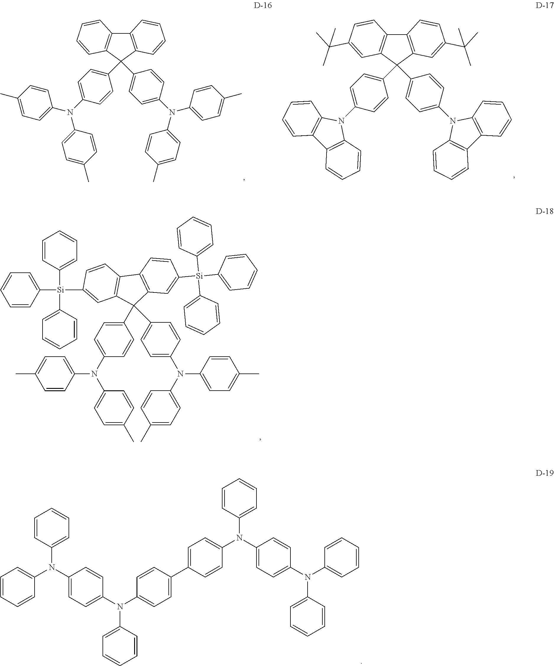
[0014] Optionally, in the organic electroluminescent device, the electron donor material is a compound containing at least one of a triphenylamine group, a diphenylamino group, and a carbazolyl group.
[0015] Optionally, in the organic electroluminescent device, the electron donor material is selected from at least one of the compounds having the structures shown below:
##STR00001## ##STR00002## ##STR00003## ##STR00004##
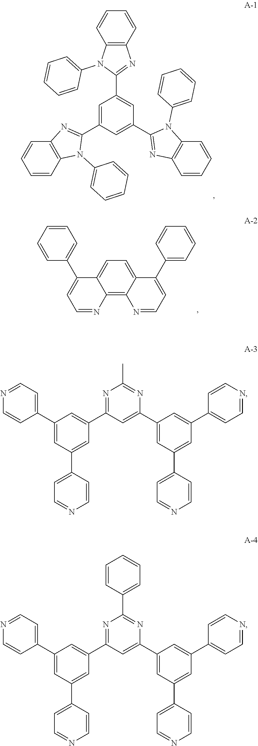
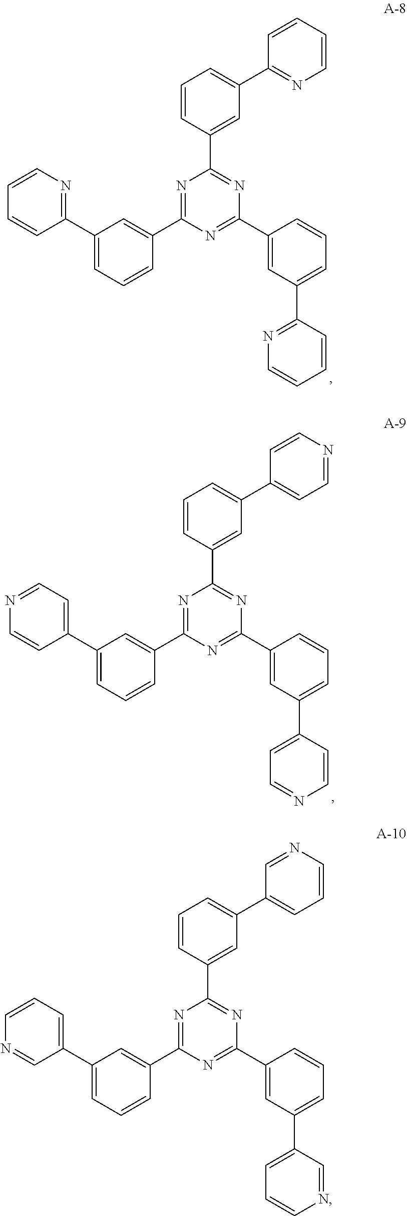
[0016] Optionally, in the organic electroluminescent device, the electron acceptor material is a compound containing at least one of a pyridyl group, a pyrimidine group, a triazine group, an imidazole group, and a phenanthroline group.
[0017] Optionally, in the organic electroluminescent device, the electron acceptor material is selected from at least one of the compounds having the structures shown below:
##STR00005## ##STR00006## ##STR00007## ##STR00008## ##STR00009## ##STR00010## ##STR00011## ##STR00012## ##STR00013## ##STR00014## ##STR00015## ##STR00016##
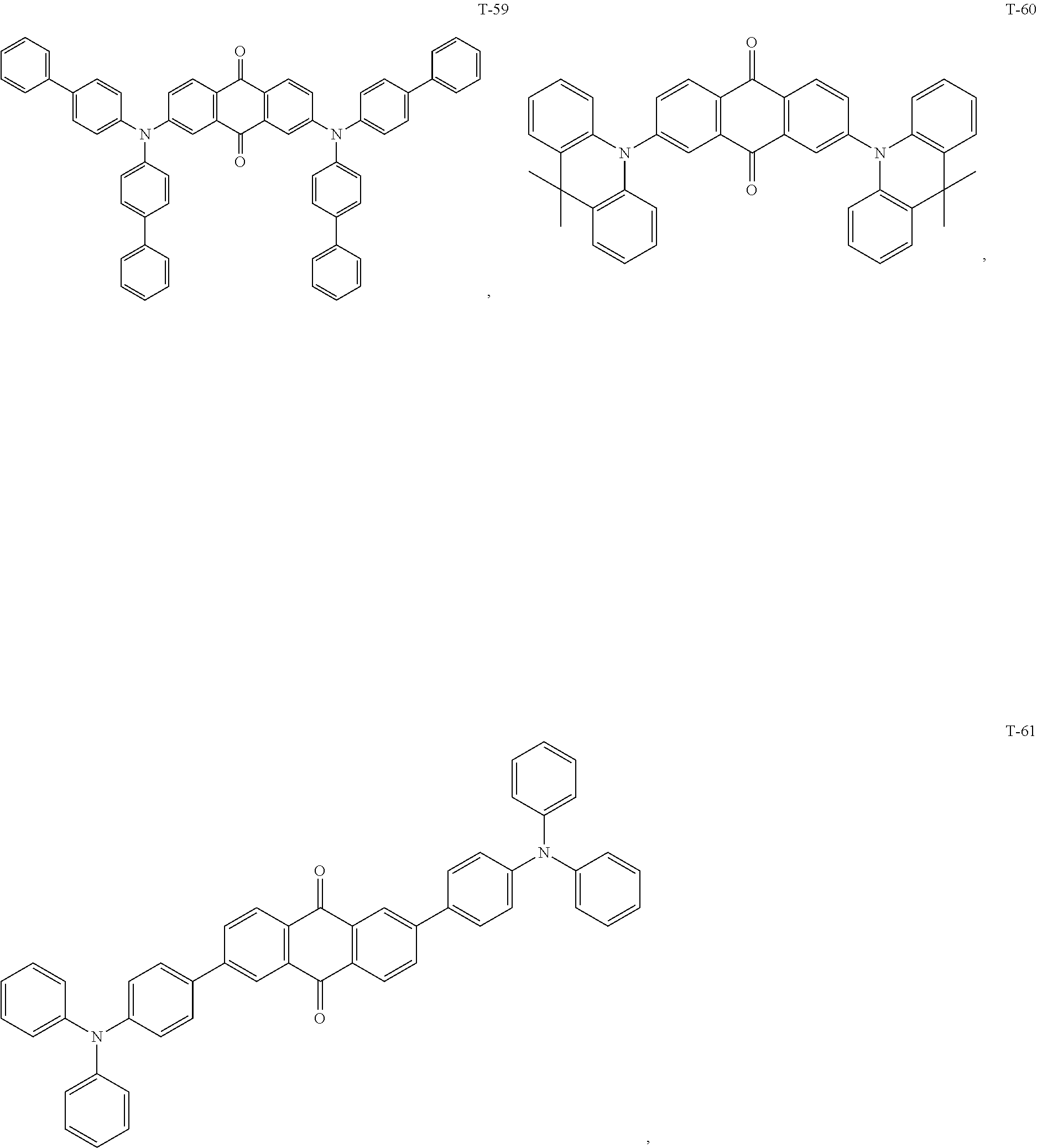
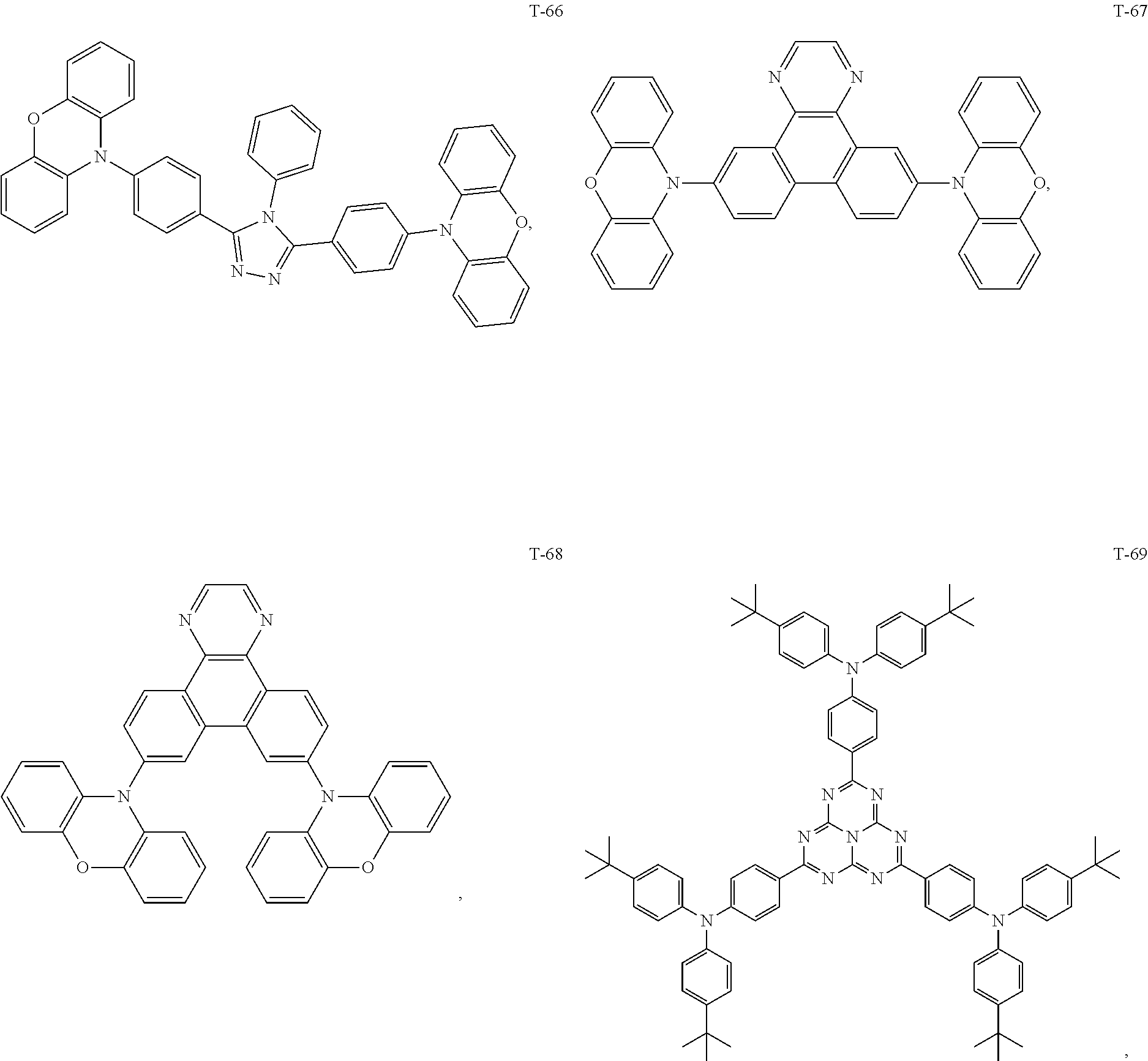
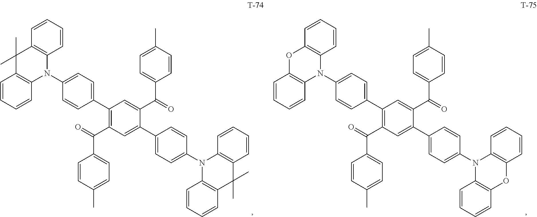
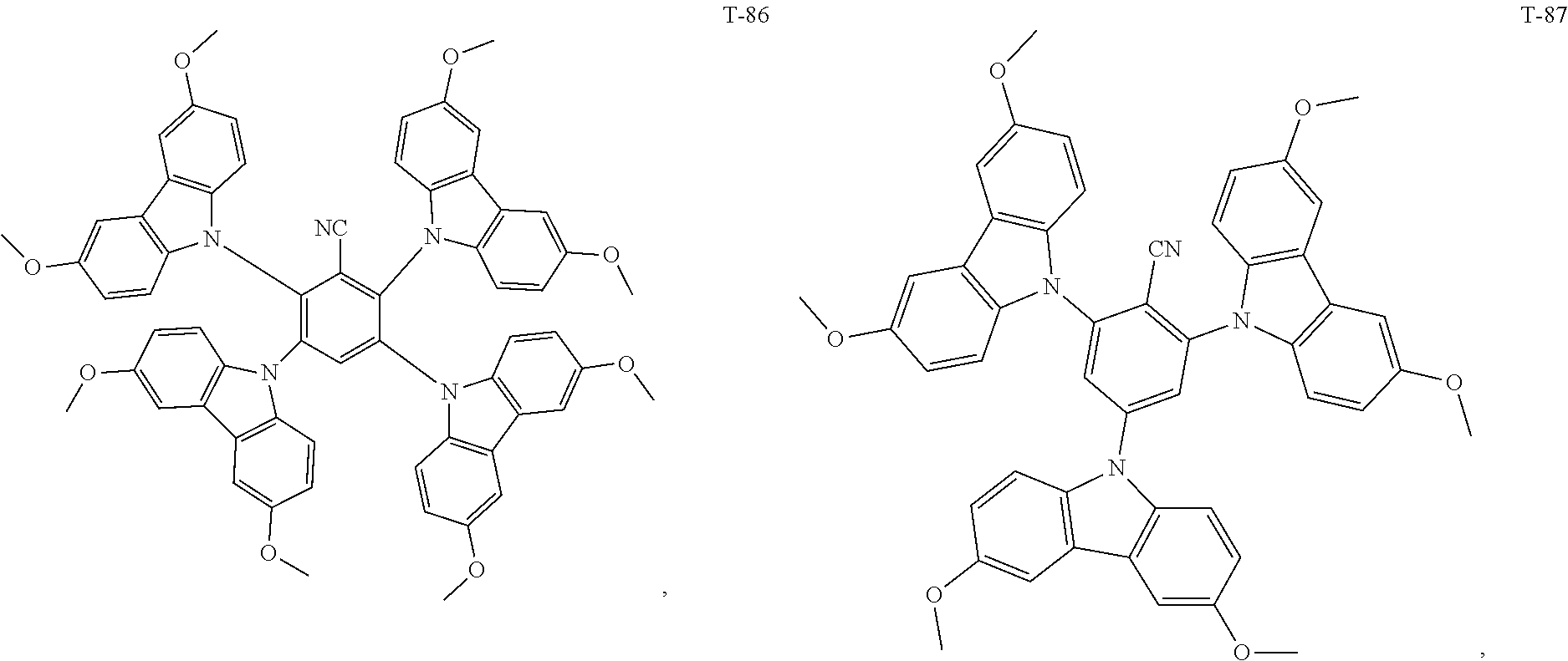
[0018] Optionally, in the organic electroluminescent device, the thermally activated delayed fluorescence material is selected from at least one of the compounds having the structure shown below:
##STR00017## ##STR00018## ##STR00019## ##STR00020## ##STR00021## ##STR00022## ##STR00023## ##STR00024## ##STR00025## ##STR00026## ##STR00027## ##STR00028## ##STR00029## ##STR00030## ##STR00031## ##STR00032## ##STR00033## ##STR00034## ##STR00035## ##STR00036## ##STR00037## ##STR00038## ##STR00039## ##STR00040## ##STR00041## ##STR00042## ##STR00043## ##STR00044## ##STR00045## ##STR00046## ##STR00047## ##STR00048##
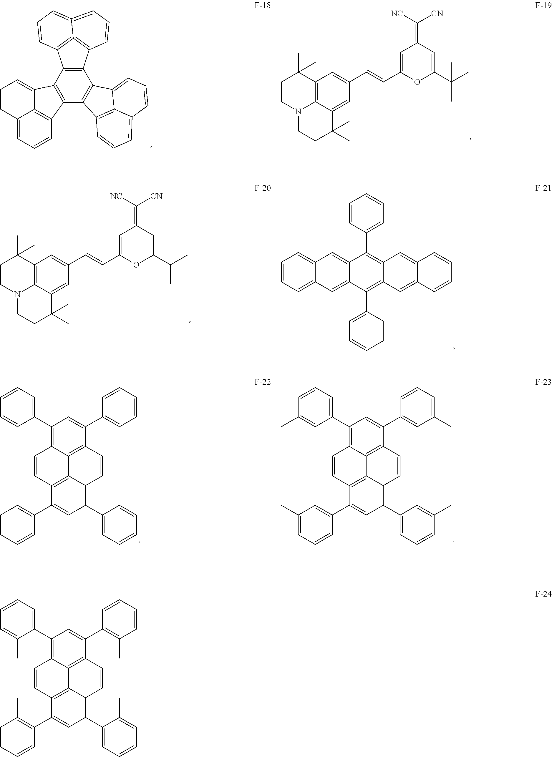
[0019] Optionally, in the organic electroluminescent device, the fluorescent dye is selected from at least one of the compounds having the structures shown below:
##STR00049## ##STR00050## ##STR00051##
[0020] Another aspect of the present disclosure provides a method for preparing an organic electroluminescent device, comprising the steps of: sequentially preparing an anode, a hole transport layer, a light-emitting layer, an electron transport layer, and a cathode on a substrate;
[0021] wherein, the light-emitting layer is prepared by simultaneously evaporating an electron donor material, an electron acceptor material, an auxiliary host material with thermally activated delayed fluorescence characteristics and a fluorescent dye in different evaporation sources respectively; or
[0022] the light-emitting layer layer is prepared by pre-mixing the electron donor material and the electron acceptor material in a same evaporation source, and then simultaneously evaporating the pre-mixed electron donor material and electron acceptor material, the auxiliary host material with thermally activated delayed fluorescence characteristics and the fluorescent dye in different evaporation sources respectively.
[0023] Optionally, in the method for preparing an organic electroluminescent device, when the electron donor material and the electron acceptor material are evaporated in the same evaporation source, the absolute value of the molar mass difference between the electron donor material and the electron acceptor material is less than 100 g/mol, the absolute value of the temperature difference of the sublimation temperature between the electron donor material and the electron acceptor material is less than or equal to 20.degree. C.
[0024] The technical solution of the present disclosure has the following advantages:
[0025] 1. The material of the light-emitting layer of the organic electroluminescent device provided by the present disclosure includes a host material, an auxiliary host material and a fluorescent dye. The host material is an exciplex prepared by mixing an electron donor material and an electron acceptor material. The electron donor material has a relatively deep LUMO (Lowest Unoccupied Molecular Orbital) energy level, and the electron acceptor material has a relatively shallow HOMO (Highest Occupied Molecular Orbital) energy level. When the electron donor material and the electron acceptor material form an exciplex, the HOMO energy level and the LUMO energy level of the exciplex are derived from the electron donor material and the electron acceptor, respectively, so that the exciplex is formed into a relatively narrow band gap and a small singlet S.sub.1-triplet T.sub.1 energy level difference .DELTA.E.sub.ST. Therefore, it is advantageous to realize transition of the triplet excitons of the host material to the singlet excitons through reverse intersystem crossing (RISC). The triplet energy level of the host material is higher than the singlet state energy level of the auxiliary host material, thereby facilitating Forster energy transfer from the singlet S.sub.1 of the host material to the singlet S.sub.1 of the auxiliary host material and the singlet S.sub.1 of the dye, increasing effective energy transfer, improving the efficiency of organic electroluminescent devices. The auxiliary host material is a thermally activated delayed fluorescence material (TADF), which has a small singlet-triplet energy level difference, and not only can accept the energy of the host material transferred to the singlet state S.sub.1 through the Forster energy transfer and transferred to the triplet T.sub.1 through the short-range Dexter energy, but also can convert the triplet excitons into singlet excitons through reverse intersystem crossing (RISC), and then transfer to the singlet S.sub.1 of dye through Forster energy transfer, and finally emit fluorescence by radiation transition of singlet exciton of the dye. Therefore, the Forster energy and the singlet exciton ratio are further improved, and at the same time, the triplet excitons are suppressed, the exciton loss is effectively reduced, and the luminous efficiency of the device is improved. TADF as an auxiliary material should be matched with HOMO and LUMO of the transport layer materials to avoid direct recombination of carriers on the fluorescent dye.
[0026] At the same time, the light-emitting layer formed by co-doping the exciplex as the host material with the auxiliary host material and the fluorescent dye can greatly reduce the Dexter energy transfer from the triplet T.sub.1 of the host material to the triplet T.sub.1 of the fluorescent dye, avoiding molecular bond cleavage caused by excessive triplet exciton energy of fluorescent dye molecules, suppressing triplet-polaron quenching (TPQ) in devices, thereby improving the lifetime of the devices, so that the organic electroluminescent devices have high external quantum efficiency, low efficiency roll-off and long lifetime, facilitating efficient use of the device for a long time.
[0027] On the other hand, due to the narrow band gap of the host material, the driving voltage of the device is lowered, which further improves the lifetime of the device and saves energy.
[0028] 2. The mass ratio of the electron donor material to the electron acceptor material provided by the present disclosure can promote the interaction between molecules in an excited state and promote the formation of an exciplex having a narrow band gap.
[0029] 3. The present disclosure provides a method for preparing an organic electroluminescent device, wherein the light-emitting layer is prepared by simultaneously evaporating an electron donor material, an electron acceptor material, an auxiliary host material (TADF) and a fluorescent dye in different evaporation sources respectively; or the light-emitting layer is prepared by pre-mixing the electron donor material and the electron acceptor material in a same evaporation source, and then simultaneously evaporating the pre-mixed electron donor material and electron acceptor material, the auxiliary host material with electron transport capability and hole transport capability and the dye in different evaporation sources respectively.
[0030] The above preparation method can prepare a light-emitting layer by co-doping an exciplex as a host material, an auxiliary host material and a dye via a three-source or four-source pre-mixing evaporation. The material of the light-emitting layer is uniformly dispersed between the electron transport layer and the hole transport layer, so that the organic electroluminescent device has high luminous efficiency and long lifetime.
BRIEF DESCRIPTION OF THE DRAWINGS
[0031] To describe the technical solutions of the embodiments of the present disclosure or the prior art more clearly, the following briefly introduces the accompanying drawings required for describing the embodiments or the prior art. Apparently, the accompanying drawings in the following description show some embodiments of the present disclosure, and persons skilled in the art may also derive other drawings from these accompanying drawings without creative efforts.
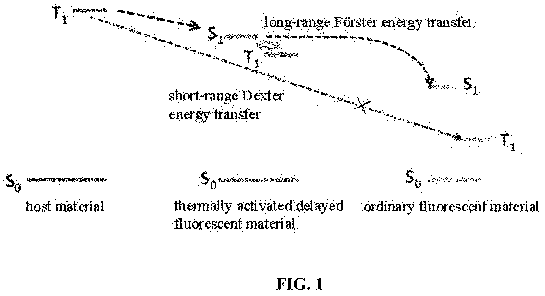
[0032] FIG. 1 is a schematic diagram showing the energy level transfer of an organic electroluminescent device in the prior art;
[0033] FIG. 2 is fluorescence spectra (emission spectrum) of an electron donor material, an electron acceptor material, and a mixture of them, according to Embodiment 1 of the present disclosure;
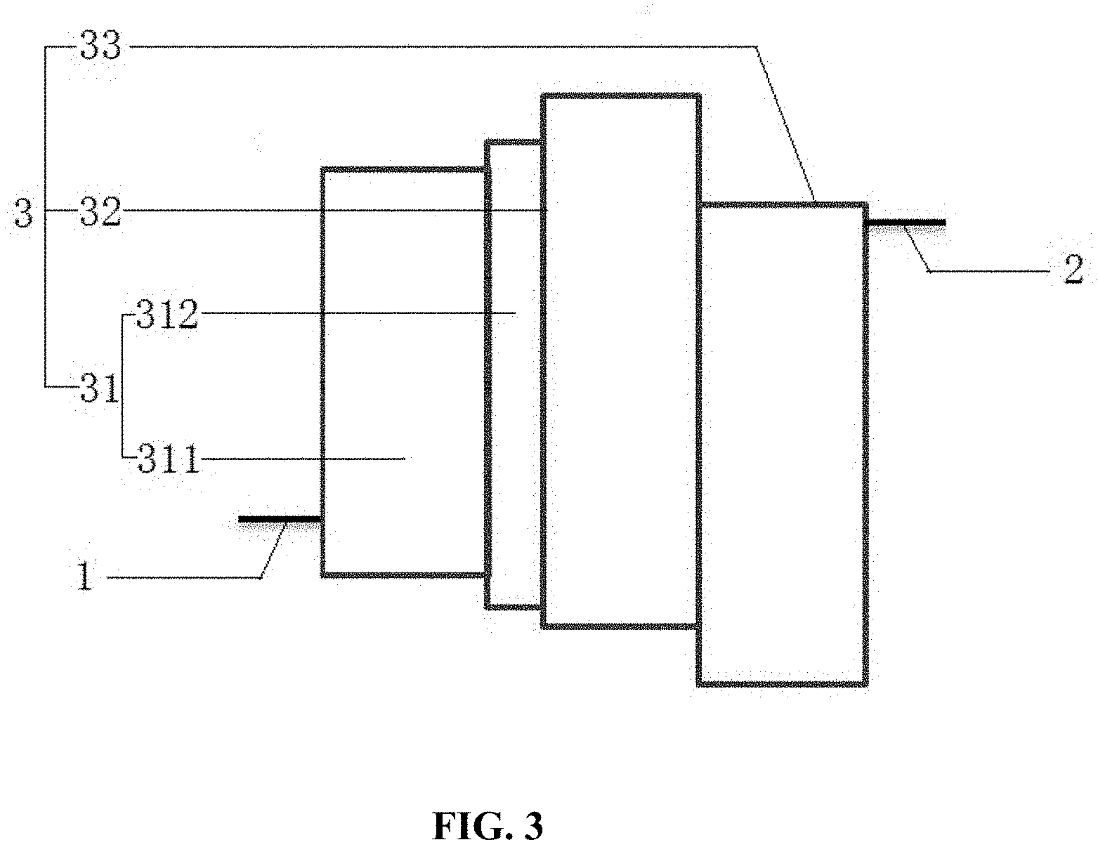
[0034] FIG. 3 is a schematic structural view of an organic electroluminescent device according to Embodiment 1 of the present disclosure;
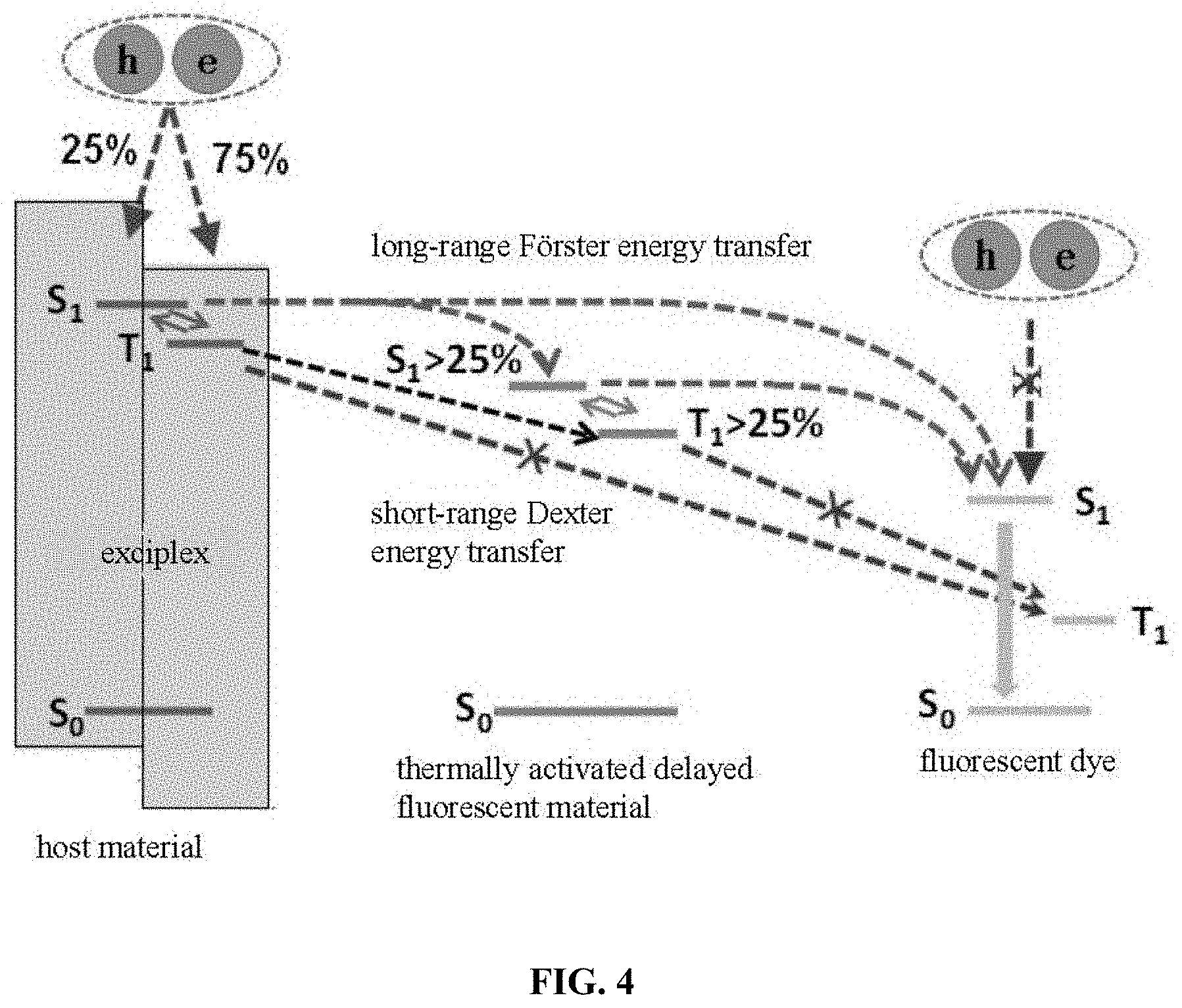
[0035] FIG. 4 is a schematic diagram of energy level transfer of an organic electroluminescent device in the present disclosure;
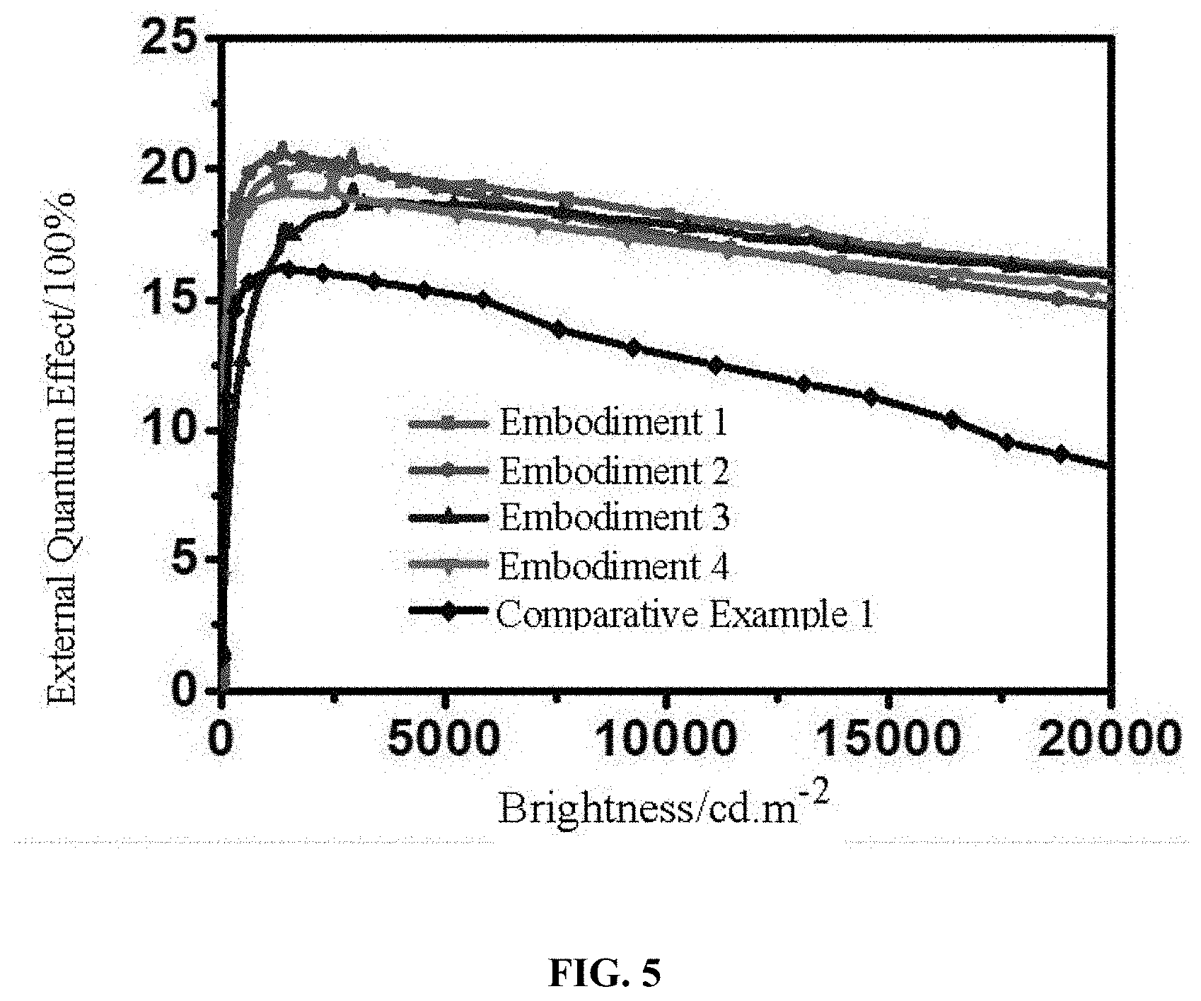
[0036] FIG. 5 is a test spectrum of organic electroluminescent devices in Embodiments 1-4 and Comparative Example 1 of the present disclosure.
DETAILED DESCRIPTION OF THE INVENTION
[0037] In an existing organic electroluminescent device, a wide band gap material is used as a host material, and a double doping system is used. There are two kinds of objects in such a system, one of which is a thermally activated delayed fluorescence (TADF) material as an auxiliary host, and the other is an ordinary fluorescent material. The principle of illumination is shown in FIG. 1. Although it can increase the Coulomb effect (Forster energy transfer) of the TADF material molecule to the fluorescent material molecule, there is energy transfer from the triplet T.sub.1 of the host material to the triplet T.sub.1 of the fluorescent material molecule through the exchange function (Dexter energy transfer), resulting in damage of device luminous efficiency; on the other hand, due to the wide band gap of the host material, the device has a higher driving voltage.
[0038] The technical solutions of the present disclosure are clearly and completely described in the following with reference to the accompanying drawings. It is obvious that the described embodiments are a part of the embodiments of the present disclosure, and not all of the embodiments. All other embodiments obtained by persons skilled in the art based on the embodiments of the present disclosure without creative efforts shall fall within the protection scope of the present disclosure.
[0039] In the description of the present disclosure, it is to be noted that the terms "first", "second", and "third" are used for descriptive purposes only, and are not to be construed as indicating or implying relative importance.
[0040] The present disclosure may be implemented in many different forms and should not be construed as being limited to the embodiments set forth herein. In contrast, these embodiments are provided so that the present disclosure will be thorough and complete, and the concept of the present disclosure will be fully conveyed to those skilled in the art, and the present disclosure will only be defined by the claims. In the accompanying drawings, dimensions and relative dimensions of layers and regions may be exaggerated for clarity. It should be understood that when an element such as a layer is referred to as "formed on" or "provided on" another element, the element may be provided directly on another element, or there may be an intermediate element. In contrast, when an element is refer to as "directly formed on" or "directly provided on" another element, there is no intermediate element.
Embodiment 1
[0041] The present embodiment provides an organic electroluminescent device including a light-emitting layer. The light-emitting layer is formed by co-doping a host material, a TADF auxiliary host material and a fluorescent dye. The host material is an exciplex formed by mixing an electron donor material and an electron acceptor material.
The electron donor material has a molecular structure shown below:
##STR00052##
[0042] the electron acceptor material has a molecular structure shown below:
##STR00053##
[0043] As shown in FIG. 2, the spectrum of the mixture of the electron donor material and the electron acceptor material are significantly red-shifted as compared with the emission spectra of the electron donor material and the electron acceptor material, indicating that they form an exciplex.
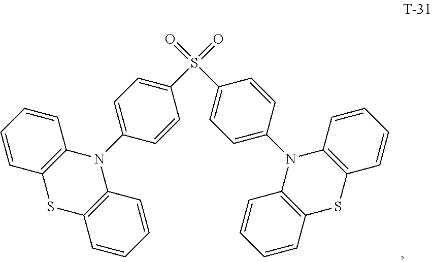
[0044] The TADF auxiliary host material (PXZ-DPS) has a molecular structure (T-31) shown below:
##STR00054##
[0045] the fluorescent dye (YH201) has a molecular structure (F-8) shown below:
##STR00055##
[0046] The singlet S.sub.1 and the triplet T.sub.1 energy levels of the host material are higher than the singlet S.sub.1 and the triplet T.sub.1 energy levels of the TADF auxiliary host material. The singlet S.sub.1 and the triplet T.sub.1 energy levels of the TADF auxiliary host material are higher than the singlet S.sub.1 and the triplet T.sub.1 energy levels of the fluorescent dye. The singlet S.sub.1 and triplet T.sub.1 energy levels of the electron donor material and the singlet S.sub.1 and triplet T.sub.1 energy levels of the electron acceptor material are higher than the singlet S.sub.1 and triplet T.sub.1 energy levels of the exciplex.
[0047] The organic electroluminescent device has a first electrode 1, a second electrode 2, and an organic functional layer 3 between the first electrode 1 and the second electrode 2. The first electrode 1 is an anode, the second electrode 2 is a cathode, and the organic functional layer 3 includes a hole transport layer 31, a light-emitting layer 32, and an electron transport layer 33 which are laminated.
[0048] As an alternative embodiment, as shown in FIG. 3, the anode of the organic electroluminescent device is made of ITO material; and the hole transport layer 31 is made of a hole transport material: 4,4'-cyclohexyl-bis[N,N-bis(4-methylphenyl)]aniline (abbreviation: TAPC) and 4,4',4'-tris(carbazol-9-yl)triphenylamine (abbreviation: TCTA), corresponding to the formation of laminated structure of the first hole transport material region 311 and the second hole transport material region 312; the electron transport layer 33 is made of 4,7-diphenyl-1,10-phenanthroline (abbreviation: Bphen) that is a electron transport type material; the cathode is made of an electron injection material LiF and a cathode material Al to form an electron injection layer/metal layer structure: LiF/Al.
[0049] In the organic electroluminescent device, the host material of the light-emitting layer is a bulk exciplex formed by mixing an electron acceptor material and an electron donor material in a mass ratio of 1:1, and the mass ratio for the TADF auxiliary host doping is 30 wt %. The mass ratio for the fluorescent dye doping is 3 wt %. The specific structure of the organic electroluminescent device is as follows: ITO/TAPC (30 nm)/TCTA (10 nm)/host (D-1-A19 1:1): 30 wt % PXZ-DPS (TADF): 3 wt % YH201 (F)/Bphen (40 nm)/LiF (0.5 nm)/Al (150 nm).
[0050] The luminescence mechanism of the above organic electroluminescent device is shown in FIG. 4: the host material formed by the bulk exciplex has a relatively narrow band gap and a small singlet-triplet energy level difference .DELTA.E.sub.ST. The carriers recombined in the host material can be converted from triplet excitons to singlet excitons by reverse intersystem crossing (RISC) transition. The triplet energy level of the host material is higher than the singlet energy level of the TADF auxiliary host material, which can promote the Forster energy transfer from the singlet S.sub.1 of the host material to the singlet S.sub.1 of the auxiliary host material and the singlet S.sub.1 of the fluorescent dye, thereby increasing the effective energy transfer, improving the efficiency of organic electroluminescent devices. The TADF auxiliary host material matches the HOMO energy level and the LUMO energy level of the transport layer material to avoid direct recombination of carriers on the fluorescent dye. The TADF auxiliary host material has a small singlet-triplet energy level difference, which not only can accept the energy of the host material transferred to the singlet state S.sub.1 through the Forster energy transfer and transferred to the triplet T.sub.1 through the short-range Dexter energy, but also can convert the triplet excitons into singlet excitons through reverse intersystem crossing (RISC), and then transfer to the singlet S.sub.1 of fluorescent dye through Forster energy transfer, and finally emit fluorescence by radiation transition of the singlet exciton of the fluorescent dye, further improving the Forster energy and singlet exciton ratio, suppressing the triplet excitons, avoiding the efficiency roll-off effect of the organic electroluminescent device, and improving the external quantum efficiency of the device, thereby achieving high device efficiency.
[0051] In addition, the exciplex as the host material can reduce the Dexter energy transfer from the triplet T.sub.1 of the host material to the triplet T.sub.1 of the fluorescent dye, avoid the molecular bond cleavage caused by the excessive triplet exciton energy of the fluorescent dye molecule, and suppress the triplet-polaron quenching (TPQ) in the device, thereby improving the lifetime of device and achieving efficient use of the device for a long time.
Embodiment 2
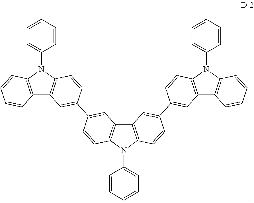
[0052] The present embodiment provides an organic electroluminescent device having the same structure as that of Embodiment 1, except that the electron donor material of the formed exciplex has the structure shown by the following D-2:
##STR00056##
[0053] The structure of the organic electroluminescent device is as follows: ITO/TAPC (30 nm)/TCTA (10 nm)/host (D-2-A19 1:1): 30 wt % PXZ-DPS (TADF): 3 wt % YH201 (F)/Bphen (40 nm)/LiF (0.5 nm)/Al (150 nm).
Embodiment 3
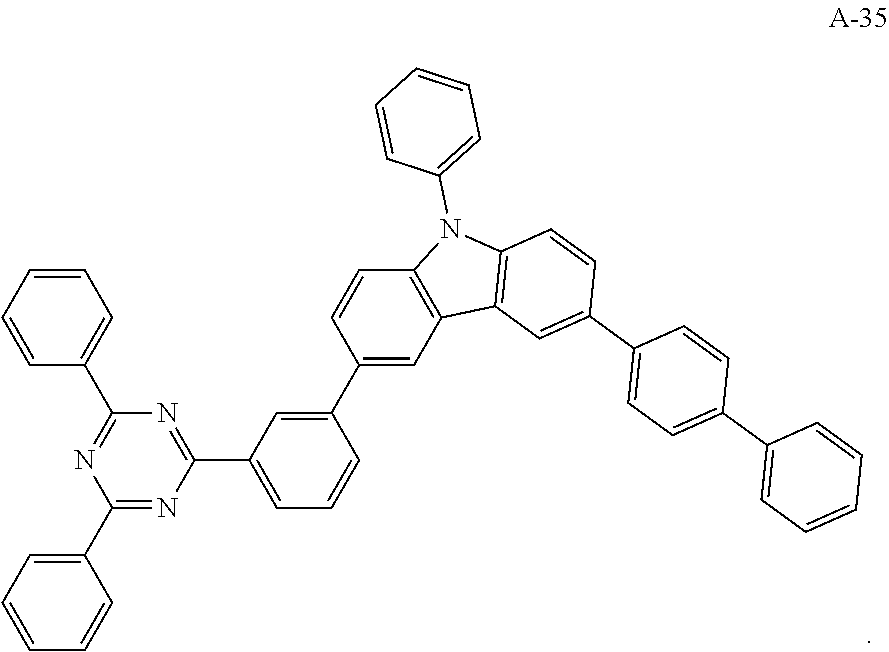
[0054] The present embodiment provides an organic electroluminescent device having the same structure as that of Embodiment 1, except that the electron acceptor material of the formed exciplex has the structure shown by the following A-35:
##STR00057##
[0055] The structure of the organic electroluminescent device is as follows: ITO/TAPC (30 nm)/TCTA (10 nm)/host (D-1-A-35 1:1): 30 wt % PXZ-DPS (TADF): 3 wt % YH201 (F)/Bphen (40 nm)/LiF (0.5 nm)/Al (150 nm).
Embodiment 4
[0056] The embodiment provides an organic electroluminescent device having the same structure as that of Embodiment 3, except that the electron donor material D-1 and the electron acceptor material A-35 of the formed exciplex are placed in the same evaporation source for pre-mixing, and the specific structure of the organic electroluminescent device is as follows: ITO/TAPC (30 nm)/TCTA (10 nm)/host (D-1-A-35 1:1): 30 wt % PXZ-DPS (TADF): 3 wt % YH201(F)/Bphen (40 nm)/LiF (0.5 nm)/Al (150 nm).
Embodiment 5
[0057] The present embodiment provides an organic electroluminescent device, which is different from Embodiment 1 in that: the electron donor material has a structure shown by D-11, and the electron acceptor material has a structure shown by A-10, and the mass ratio of the electron donor material to the electron acceptor material is 1:9; the thermally activated delayed fluorescence material has a structure shown by T-1, the doping ratio of TADF is 5 wt %, and the fluorescent dye has a structure shown by F-12, the doping ratio of the fluorescent dye is 0.1 wt %. The device has an external quantum efficiency of 19.5% and a chromaticity coordinate of (0.50, 0.50) at a brightness of 10000 cd/m.sup.2.
Embodiment 6
[0058] The present embodiment provides an organic electroluminescent device, which is different from Embodiment 1 in that: the electron donor material has a structure shown by D-3, and the electron acceptor material has a structure shown by A-26, and the mass ratio of the electron donor material to the electron acceptor material is 9:1; the thermally activated delayed fluorescence material has a structure shown by T-5, the doping ratio of TADF is 80 wt %, and the fluorescent dye has a structure shown by F-5, the doping ratio of the fluorescent dye is 1 wt %. The device has an external quantum efficiency of 15.8% and a chromaticity coordinate of (0.36, 0.57) at a brightness of 10000 cd/m.sup.2.
Embodiment 7
[0059] The present embodiment provides an organic electroluminescent device, which is different from Embodiment 1 in that: the electron donor material has a structure shown by D-4, and the electron acceptor material has a structure shown by A-3, and the mass ratio of the electron donor material to the electron acceptor material is 1:3; the thermally activated delayed fluorescence material has a structure shown by T-17, the doping ratio of TADF is 4 wt %, and the fluorescent dye has a structure shown by F-7, the doping ratio of the fluorescent dye is 10 wt %. The device has an external quantum efficiency of 16.2% and a chromaticity coordinate of (0.36, 0.57) at a brightness of 10000 cd/m.sup.2.
Embodiment 8
[0060] The present embodiment provides an organic electroluminescent device, which is different from Embodiment 1 in that: the electron donor material has a structure shown by D-7, and the electron acceptor material has a structure shown by A-7, and the mass ratio of the electron donor material to the electron acceptor material is 4:1; the thermally activated delayed fluorescence material has a structure shown by T-31, the doping ratio of TADF is 15 wt %, and the fluorescent dye has a structure shown by F-6, the doping ratio of the fluorescent dye is 10 wt %. The device has an external quantum efficiency of 17.8% and a chromaticity coordinate of (0.37, 0.58) at a brightness of 10000 cd/m.sup.2.
Embodiment 9
[0061] The present embodiment provides an organic electroluminescent device, which is different from Embodiment 1 in that: the electron donor material has a structure shown by D-12, and the electron acceptor material has a structure shown by A-16, and the mass ratio of the electron donor material to the electron acceptor material is 1:5; the thermally activated delayed fluorescence material has a structure shown by T-50, the doping ratio of TADF is 65 wt %, and the fluorescent dye has a structure shown by F-9, the doping ratio of the fluorescent dye is 5 wt %. The device has an external quantum efficiency of 15.1% and a chromaticity coordinate of (0.44, 0.55) at a brightness of 10000 cd/m.sup.2.
Embodiment 10
[0062] The present embodiment provides an organic electroluminescent device, which is different from Embodiment 1 in that: the electron donor material has a structure shown by D-15, and the electron acceptor material has a structure shown by A-17, and the mass ratio of the electron donor material to the electron acceptor material is 2:1; the thermally activated delayed fluorescence material has a structure shown by T-66, the doping ratio of TADF is 70 wt %, and the fluorescent dye has a structure shown by F-10, the doping ratio of the fluorescent dye is 8 wt %. The device has an external quantum efficiency of 14.6% and a chromaticity coordinate of (0.43, 0.55) at a brightness of 10000 cd/m.sup.2.
Embodiment 11
[0063] The present embodiment provides an organic electroluminescent device, which is different from Embodiment 1 in that: the electron donor material has a structure shown by D-18, and the electron acceptor material has a structure shown by A-21, and the mass ratio of the electron donor material to the electron acceptor material is 1:8; the thermally activated delayed fluorescence material has a structure shown by T-70, the doping ratio of TADF is 25 wt %, and the fluorescent dye has a structure shown by F-19, the doping ratio of the fluorescent dye is 0.5 wt %. The device has an external quantum efficiency of 13.8% and a chromaticity coordinate of (0.59, 0.41) at a brightness of 10000 cd/m.sup.2.
Embodiment 12
[0064] The present embodiment provides an organic electroluminescent device, which is different from Embodiment 1 in that: the electron donor material has a structure shown by D-19, and the electron acceptor material has a structure shown by A-32, and the mass ratio of the electron donor material to the electron acceptor material is 3:1; the thermally activated delayed fluorescence material has a structure shown by T-76, the doping ratio of TADF is 30 wt %, and the fluorescent dye has a structure shown by F-20, the doping ratio of the fluorescent dye is 1 wt %. The device has an external quantum efficiency of 13.5% and a chromaticity coordinate of (0.59, 0.40) at a brightness of 10000 cd/m.sup.2.
Embodiment 13
[0065] The present embodiment provides an organic electroluminescent device, which is different from Embodiment 1 in that: the electron donor material has a structure shown by D-16, and the electron acceptor material has a structure shown by A-33, and the mass ratio of the electron donor material to the electron acceptor material is 6:1; the thermally activated delayed fluorescence material has a structure shown by T-99, the doping ratio of TADF is 50 wt %, and the fluorescent dye has a structure shown by F-11, the doping ratio of the fluorescent dye is 2 wt %. The device has an external quantum efficiency of 14.2% and a chromaticity coordinate of (0.49, 0.50) at a brightness of 10000 cd/m.sup.2.
[0066] In the above embodiments, the electron donor material, the electron acceptor material, the auxiliary host material, and the fluorescent dye are simultaneously evaporated in different evaporation sources to form a light-emitting layer; or the electron donor material and the electron acceptor material after being pre-mixed in the same evaporation source are evaporated simultaneously with the auxiliary host material and the fluorescent dye in different evaporation sources to form a light-emitting layer.
[0067] As an alternative embodiment, the electron donor material in the above embodiment may be replaced with an electron donor material having any of the structures shown by D-1 to D-19.
[0068] As an alternative embodiment, the electron acceptor material in the above embodiment may be replaced with an electron acceptor material having any of the structures shown by A-1 to A-35.
[0069] As an alternative embodiment, the thermally activated delayed fluorescence material in the above embodiment may be replaced with a thermally activated delayed fluorescence material having any of the structures shown by T-1 to T-99.
[0070] As an alternative embodiment, the fluorescent dye in the above embodiment may be replaced with a fluorescent dye having any of the structures shown by F-1 to F-24.
[0071] As an alternative embodiment, the mass ratio of the electron donor material to the electron acceptor material in the above embodiment may be any ratio ranging from 1:9 to 9:1.
[0072] As an alternative embodiment, the doping ratio of TADF in the above embodiment may be any ratio ranging from 5 wt % to 80 wt %.
[0073] As an alternative embodiment, the doping ratio of the fluorescent dye in the above embodiment may be any ratio ranging from 0.1 wt % to 10 wt %.
Comparative Example 1
[0074] The present comparative example provides an organic electroluminescent device having the same structure as that of Embodiment 1. This organic electroluminescent device differs from the organic electroluminescent device provided in Embodiment 1 only in that the host material in the light-emitting layer is host mCBP with a wide band gap. mCBP has the structure shown below:
##STR00058##
Test Example 1
[0075] Characteristics of the device such as current, voltage, brightness, and luminescence spectra etc. were tested simultaneously using a PR 650 spectral scanning luminance meter and a Keithley K 2400 source meter system. The organic electroluminescent devices provided in Embodiments 1-4 and Comparative Example 1 were tested, and the results are shown in Table 1 and FIG. 5. The external quantum efficiency (EQE) of the devices provided in Embodiments 1-4 was greater than that of the device in Comparative Example 1, and the efficiency roll-off was smaller than that of the device in Comparative Example 1.
TABLE-US-00001 TABLE 1 External External quantum quantum Driving efficiency efficiency voltage/V Chroma- (%), at a (%), at a brightness ticity brightness brightness 5000 coordinate of 5000 of 10000 roll- cd/m.sup.2 CIE (x, y) cd/m.sup.2 cd/m.sup.2 off Embodiment 1 3.60 (0.36, 19.4 18.5 4.64% 0.58) Embodiment 2 3.62 (0.36, 19.0 17.8 6.31% 0.58) Embodiment 3 3.70 (0.36, 18.6 17.9 3.76% 0.58) Embodiment 4 3.82 (0.36, 18.4 17.2 6.52% 0.58) Comparative 5.20 (0.36, 15.1 13.0 14.47% Example 1 0.58)
[0076] It is apparent that the above-described embodiments are merely examples for clear descriptions, but not intended to limit the implementations. Other changes or variations of the various forms may be made by those skilled in the art based on the above description. There is no need and no way to exhaust all of the implementations. Obvious changes or variations resulting therefrom are still within the scope of the disclosure.
* * * * *


D00000

D00001
D00002

D00003
D00004
D00005
XML
uspto.report is an independent third-party trademark research tool that is not affiliated, endorsed, or sponsored by the United States Patent and Trademark Office (USPTO) or any other governmental organization. The information provided by uspto.report is based on publicly available data at the time of writing and is intended for informational purposes only.
While we strive to provide accurate and up-to-date information, we do not guarantee the accuracy, completeness, reliability, or suitability of the information displayed on this site. The use of this site is at your own risk. Any reliance you place on such information is therefore strictly at your own risk.
All official trademark data, including owner information, should be verified by visiting the official USPTO website at www.uspto.gov. This site is not intended to replace professional legal advice and should not be used as a substitute for consulting with a legal professional who is knowledgeable about trademark law.