Method Of Detecting A Difference In Level Of A Surface In Front Of A Robotic Cleaning Device
Forsberg; Petter ; et al.
U.S. patent application number 16/612913 was filed with the patent office on 2020-03-12 for method of detecting a difference in level of a surface in front of a robotic cleaning device. The applicant listed for this patent is Aktiebolaget Electrolux. Invention is credited to Petter Forsberg, Andreas Klintemyr, Magnus Lindhe.
| Application Number | 20200081451 16/612913 |
| Document ID | / |
| Family ID | 59054098 |
| Filed Date | 2020-03-12 |


View All Diagrams
| United States Patent Application | 20200081451 |
| Kind Code | A1 |
| Forsberg; Petter ; et al. | March 12, 2020 |
METHOD OF DETECTING A DIFFERENCE IN LEVEL OF A SURFACE IN FRONT OF A ROBOTIC CLEANING DEVICE
Abstract
A method for a robotic cleaning device of detecting a difference in level of a surface in front of the robotic cleaning device moves. The method includes illuminating the surface with light, capturing an image of the surface, detecting a luminous section in the captured image caused by the light, identifying at least a first segment and a second segment representing the detected luminous section, and detecting, from a positional relationship between the identified first and second segment, the difference in level of the surface.
| Inventors: | Forsberg; Petter; (Stockholm, SE) ; Lindhe; Magnus; (Stockholm, SE) ; Klintemyr; Andreas; (Stockholm, SE) | ||||||||||
| Applicant: |
|
||||||||||
|---|---|---|---|---|---|---|---|---|---|---|---|
| Family ID: | 59054098 | ||||||||||
| Appl. No.: | 16/612913 | ||||||||||
| Filed: | June 2, 2017 | ||||||||||
| PCT Filed: | June 2, 2017 | ||||||||||
| PCT NO: | PCT/EP2017/063468 | ||||||||||
| 371 Date: | November 12, 2019 |
| Current U.S. Class: | 1/1 |
| Current CPC Class: | G05D 2201/0203 20130101; G06T 7/55 20170101; A47L 9/2815 20130101; A47L 2201/04 20130101; G05D 1/0246 20130101; G05D 2201/0215 20130101; A47L 9/2826 20130101 |
| International Class: | G05D 1/02 20060101 G05D001/02; A47L 9/28 20060101 A47L009/28 |
Claims
1. A method for a robotic cleaning device of detecting a difference in level of a surface in front of the robotic cleaning device, the method comprising: illuminating the surface with light; capturing an image of the surface; detecting a luminous section in the captured image caused by the light; identifying at least a first segment and a second segment representing the detected luminous section; and detecting, from a positional relationship between the identified first and second segment, the difference in level of the surface.
2. The method of claim 1, wherein the detecting of the difference in level of the surface from a positional relationship between the identified first and second segment comprises: detecting that a discontinuity occurs between the identified first and second segment in the captured image, wherein the difference in level is detected to comprise a ledge.
3. The method of claim 1, wherein the detecting of the difference in level of the surface from a positional relationship between the identified first and second segment comprises: detecting a third segment linking the identified first and second segment (30c', 30c'') in the captured image, wherein the difference in level is detected to comprise an elevation.
4. The method of claim 2, wherein the detecting of the difference in level of the surface from a positional relationship between the identified first and second segment comprises: detecting that the identified second segment is located vertically below the identified first segment in the captured image, wherein the difference in level is detected to comprise a ledge.
5. The method of claim 3, wherein the detecting of the difference in level of the surface from a positional relationship between the identified first and second segment comprises: detecting that the identified second segment (30c'') is located vertically above the identified first segment in the captured image, wherein the difference in level is detected to comprise an elevation.
6. The method of claim 1, wherein the detecting of the difference in level of the surface from a positional relationship between the identified first and second segment comprises: determining, from coordinates of the captured image, a distance to a proximal end of the identified first segment and a vertical distance between the identified first and second segment, the vertical distance constituting a height of the detected difference in level.
7. A robotic cleaning device configured to detect a difference in level of a surface in front of the robotic cleaning device, comprising: a propulsion system configured to move the robotic cleaning device; a camera device configured to record images of a vicinity of the robotic cleaning device; at least one light source configured to illuminate a surface in front of the robotic cleaning device; and a controller configured to: control the at least one light source to illuminate a surface in front of the robotic cleaning device; control the camera device to capture an image of the illuminated surface; detect a luminous section in the captured image caused by the at least one light source illuminating the surface; identify at least a first segment and a second segment representing the detected luminous section; and to detect, from a positional relationship between the identified first and second segment, the difference in level of the surface.
8. The robotic cleaning device of claim 7, the controller further being configured to, when detecting the difference in level of the surface from a positional relationship between the identified first and second segment: detect that a discontinuity occurs between the identified first and second segment in the captured image, wherein the difference in level is detected to comprise a ledge.
9. The robotic cleaning device of claim 7, the controller further being configured to, when detecting the difference in level of the surface from a positional relationship between the identified first and second segment: detect a third segment linking the identified first and second segment in the captured image, wherein the difference in level is detected to comprise an elevation.
10. The robotic cleaning device of claim 8, the controller further being configured to, when detecting the difference in level of the surface from a positional relationship between the identified first and second segment: detect that the identified second segment is located vertically below the identified first segment in the captured image, wherein the difference in level is detected to comprise a ledge.
11. The robotic cleaning device of claim 9, the controller further being configured to, when detecting the difference in level of the surface from a positional relationship between the identified first and second segment: detect that the identified second segment is located vertically above the identified first segment in the captured image, wherein the difference in level is detected to comprise an elevation.
12. The robotic cleaning device of claim 7, the controller further being configured to, when detecting the difference in level of the surface from a positional relationship between the identified first and second segment: determine, from coordinates of the captured image, a distance to a proximal end of the identified first segment and a vertical distance between the identified first and second segment, the vertical distance constituting a height of the detected difference in level.
13. The robotic cleaning device of claim 7, the at least one light source comprising: a first and second line laser configured to illuminate said vicinity of the robotic cleaning device.
14. A computer program comprising computer-executable instructions for causing a robotic cleaning device to perform the steps recited in claim 1 when the computer-executable instructions are executed on a controller included in the robotic cleaning device.
15. The computer program of claim 14, wherein the computer-executable instructions are stored in a computer readable medium.
Description
TECHNICAL FIELD
[0001] The invention relates to a method of detecting a difference in level of a surface in front of a robotic cleaning device, and a robotic cleaning device performing the method.
[0002] Further provided is a computer program comprising computer-executable instructions for causing a robotic cleaning device to perform the steps of the method when the computer-executable instructions are executed on a controller included in the robotic cleaning device.
[0003] Yet further provided is a computer program product comprising a computer readable medium, the computer readable medium having the computer program embodied thereon.
BACKGROUND
[0004] In many fields of technology, it is desirable to use robots with an autonomous behaviour such that they freely can move around a space without colliding with possible obstacles. Robotic vacuum cleaners are known in the art, which are equipped with drive means in the form of a motor for moving the cleaner across a surface to be cleaned. The robotic vacuum cleaners are further equipped with intelligence in the form of microprocessor(s) and navigation means for causing an autonomous behaviour such that the robotic vacuum cleaners freely can move around and clean a surface in the form of e.g. a floor. Thus, these prior art robotic vacuum cleaners have the capability of more or less autonomously vacuum clean a room in which objects such as tables and chairs and other obstacles such as walls and stairs are located.
[0005] A problem with prior art robotic vacuum cleaners is that they tend to get stuck to on obstacles such as doorsteps or thick rugs
[0006] A particularly problematic obstacle encountered is a ledge, typically in the form of a stair leading down to a lower floor. If such a ledge is not detected by the robotic cleaner, there is a risk that the robot drops off the ledge, falls down the stair and becomes permanently damaged.
SUMMARY
[0007] An object of the present invention is to solve, or at least mitigate, this problem in the art and to provide and improved method of detecting a difference in level of a surface in front of the robotic cleaning device.
[0008] This object is attained in a first aspect of the invention by a method for a robotic cleaning device of detecting a difference in level of a surface in front of the robotic cleaning device. The method comprises illuminating the surface with light, capturing an image of the surface, detecting a luminous section in the captured image caused by the light, identifying at least a first segment and a second segment representing the detected luminous section, and detecting, from a positional relationship between the identified first and second segment, the difference in level of the surface.
[0009] This object is attained in a second aspect of the invention by a robotic cleaning device configured to detect a difference in level of a surface in front of the robotic cleaning device. The robotic cleaning device comprises a propulsion system configured to move the robotic cleaning device, a camera device configured to record images of a vicinity of the robotic cleaning device, and at least one light source configured to illuminate a surface in front of the robotic cleaning device. The robotic cleaning device further comprises a controller configured to control the at least one light source to illuminate a surface in front of the robotic cleaning device, control the camera device to capture an image of the illuminated surface, detect a luminous section in the captured image caused by the at least one light source illuminating the surface, identify at least a first segment and a second segment representing the detected luminous section, and to detect, from a positional relationship between the identified first and second segment, the difference in level of the surface.
[0010] Advantageously, by measuring a difference in level of the surface in front of the robotic device, it is possible to timely plan how the robotic device should move for performing a cleaning programme--well before an object or surface is encountered--and further to be able avoid traversing an object such as for example a doorstep, the height of which may be to great for the robotic device to traverse.
[0011] Further advantageous is that by detecting height of objects or surfaces in front of the robotic cleaning device, for instance a thick rug, the robot may be controlled to move along the periphery of the rug thereby making efficient use of any side brushes with which the robot may be equipped. After having cleaned along the periphery of the rug, the robotic cleaning device may move up onto the rug, where it typically would refrain from using the side brush. Instead, the robot could alternately rotate a rotatable brush roll, with which the robot may be equipped, in a forward and backward direction to avoid having the fibers of the rug being entangled in the brush roll. Hence, the movement of any brush roll and any side brush(es) can advantageously be controlled by taking into account the determined height of the surfaces and objects in front of the robotic cleaning device.
[0012] In an embodiment, the robotic device detects that a discontinuity occurs between the identified first and second segment in the captured image, wherein the difference in level is detected to comprise a ledge.
[0013] In this embodiment, which advantageously can be implemented for less complex robotic devices, the difference in level of the floor in front of the robotic device is detected by concluding from the captured image that the first and second segment are discontinuous.
[0014] If such a discontinuity occurs, the robotic cleaning device concludes in one embodiment that a floor on a distance in front of the robotic cleaning device is located at a lower level than a floor immediately in front of the robotic cleaning device. However, if such a method is used, the robotic device only knows that there is difference in level, but cannot assess a height of the difference in level.
[0015] In another embodiment, the robotic device determines if the second segment is located vertically below the first segment in the captured image, in which case the difference in level constitutes a ledge.
[0016] In a further embodiment, which advantageously can be implemented for less complex robotic devices, the difference in level of the floor in front of the robotic device is detected by concluding from the image that the first and second segment are linked by a third segment.
[0017] If such a linking segment between the first and the second segment is present in the captured image, the robotic device concludes that the floor on a distance from the robotic cleaning device is located on a higher level than a floor immediately in front of the robotic cleaning device. Hence, an elevation has been encountered.
[0018] In another embodiment, the robotic device determines if the second segment is located vertically above the first segment, in which case the difference in level constitutes an elevation.
[0019] In yet an embodiment, the robotic device determines a distance to e.g. a ledge and a height of the ledge.
[0020] Thus, a more elaborate robotic cleaning device can determine, from x and y image coordinates, the distance to the ledge and the height of the ledge, by converting image coordinates to actual real-world distances.
[0021] This information may advantageously be used for sectionalizing an area to be cleaned. For instance, the robotic device may determine that it should finish cleaning the room in which it currently is located before moving on to the next room, i.e. before descending the ledge down to a lower floor.
[0022] It may further be envisaged that the robotic device does not descend the ledge at all after having determined its height. Assuming for instance that the height of the ledge exceeds a predetermined level threshold value; this indicates that the ledge is followed by a stairway in which case the robotic device is controlled not the cross the ledge to avoid the robot falling over.
[0023] Further provided is a computer program comprising computer-executable instructions for causing a robotic cleaning device to perform the steps of the method when the computer-executable instructions are executed on a controller included in the robotic cleaning device.
[0024] Yet further provided is a computer program product comprising a computer readable medium, the computer readable medium having the computer program embodied thereon.
[0025] Generally, all terms used in the claims are to be interpreted according to their ordinary meaning in the technical field, unless explicitly defined otherwise herein. All references to "a/an/the element, apparatus, component, means, step, etc." are to be interpreted openly as referring to at least one instance of the element, apparatus, component, means, step, etc., unless explicitly stated otherwise. The steps of any method disclosed herein do not have to be performed in the exact order disclosed, unless explicitly stated.
BRIEF DESCRIPTION OF THE DRAWINGS
[0026] The invention is now described, by way of example, with reference to the accompanying drawings, in which:
[0027] FIG. 1 illustrates detection of objects on a surface over which the robotic cleaning device moves in accordance with an embodiment of the present invention;
[0028] FIG. 2a illustrates an image captured by the camera of the robotic cleaning device when in position P1 of FIG. 1 according to an embodiment;
[0029] FIG. 2b illustrates an image captured by the camera of the robotic cleaning device when in position P2 of FIG. 1 according to an embodiment;
[0030] FIG. 2c illustrates a side view of the robotic cleaning device of FIG. 1 when in position P2;
[0031] FIG. 3 shows a flowchart illustrating an embodiment of a method of detecting a difference in level of a surface over which the robotic cleaning device moves;
[0032] FIG. 4a illustrates an enlarged view of the captured image of FIG. 2b;
[0033] FIG. 4b illustrates computing distance to an encountered object according to an embodiment;
[0034] FIG. 4c illustrates computing height of an encountered object according to an embodiment;
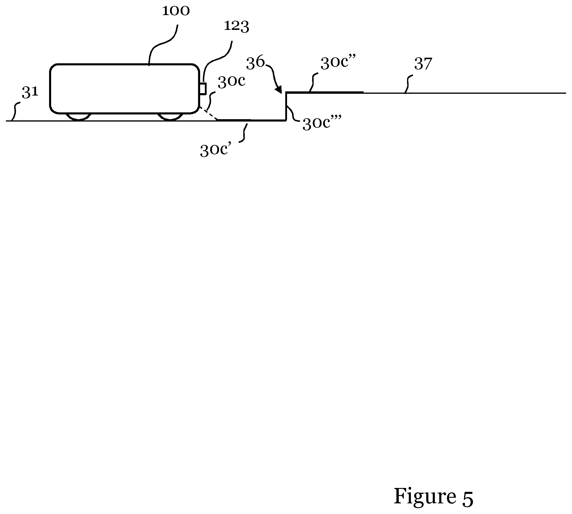
[0035] FIG. 5 illustrates a side view of the robotic cleaning device encountering an elevation;
[0036] FIG. 6 illustrates an image captured by the robotic cleaning device in the position shown in FIG. 5;
[0037] FIG. 7 shows a bottom view of a robotic cleaning device according to an embodiment; and
[0038] FIG. 8 shows a front view of a robotic cleaning device according to an embodiment.
DETAILED DESCRIPTION
[0039] The invention will now be described more fully hereinafter with reference to the accompanying drawings, in which certain embodiments of the invention are shown. This invention may, however, be embodied in many different forms and should not be construed as limited to the embodiments set forth herein; rather, these embodiments are provided by way of example so that this disclosure will be thorough and complete, and will fully convey the scope of the invention to those skilled in the art. Like numbers refer to like elements throughout the description.
[0040] The invention relates to robotic cleaning devices, or in other words, to automatic, self-propelled machines for cleaning a surface, e.g. a robotic vacuum cleaner, a robotic sweeper or a robotic floor washer. The robotic cleaning device according to the invention can be mains-operated and have a cord, be battery-operated or use any other kind of suitable energy source, for example solar energy.
[0041] FIG. 1 illustrates detection of objects on a surface over which the robotic cleaning device moves in accordance with an embodiment of the present invention.
[0042] In this particular exemplifying embodiment, the robotic device 100 uses one vertical line laser 127 for illuminating the surface (i.e. floor 31) over which it moves. However, any appropriate light source may be envisaged for illuminating the surface 31. Further, a smaller or greater part of the surface may be illuminated.
[0043] As can be seen in FIG. 1, the line laser 127 projects a laser beam 30a onto the floor 31 and a first wall 32 of a room to be cleaned, while the robotic device 100 uses its camera 123 to capture images of the illuminated surface.
[0044] FIG. 2a illustrates an image 40a captured by the camera 123 of the robotic device 100 when in first position P1.
[0045] As can be seen, the laser beam 30a will fall onto the floor 31 and the wall 32 and cause corresponding illuminated section 30a' to be present in the image. The location in the image 40a where the floor 31 meets the wall 32 is indicated with a dashed line only for illustrational purposes; the dashed line is not present in the captured image 40a. From the captured image 40a, the robotic device 100 detects that the laser beam 30a impinges on an obstacle 32, such as a wall, a sofa, a door or the like. By capturing a number of images, the robotic device 100 is capable of identifying the particular obstacle 32 with high reliability. In case a different type of light source would be used, it may even be envisaged that the illuminated section covers the entire captured image. An advantage of using the laser beam as exemplified in FIG. 1 is that a less amount of image data needs to be processed by the robotic device 100.
[0046] As is illustrated in the image 40a, since the surface over which the robotic cleaning device 100 moves when in the first position P1 is a flat and even floor 31 and thus no difference in level is present, the illuminated section 30a' caused by the laser line 30a illuminating the floor 31 is composed of a single segment in the image 40a.
[0047] Now, again with reference to FIG. 1, when the robotic cleaning device 100 moves into a second position P2, it encounters a doorway 33 where a step leads down to a lower floor 35. Again, the robotic device 100 captures an image of the illuminated surface. FIG. 2b illustrates the image 40b captured by the camera 123 of the robotic device 100 when in the second position P2.
[0048] In this image, the laser beam 30b will fall onto the (upper) floor 31 and ledge 34 indicated with a dashed line in the image 40b for illustrational purposes. Further, the part of the laser beam 30b falling beyond the ledge 34 will incide on the lower floor 35, which is indicated in the image 40b as two line segments; a first segment 30b' falling onto the upper floor 31 and a second segment 30b'' falling on the lower floor 35.
[0049] For illustration, FIG. 2c shows a side view of the robotic device 100 when in position P2, where the laser beam 30a falls onto the upper floor 31, over the ledge 34, and onto the lower floor 35, where the ledge causes a shadow; i.e. the section of the lower floor 35 obscured by the ledge 34 will not be illuminated. The first line segment 30b' and second line segment 30b'' that will appear in the captured image 40b are further indicated in FIG. 2c.
[0050] Hence, with reference to the flowchart of FIG. 3, a method of detecting a difference in level of a surface in front of the robotic cleaning device 100.
[0051] As was discussed, the robotic device 100 illuminates in step S101 the surface 31 in front of it with light, in this exemplifying embodiment with structured vertical light using the line laser 127, and captures images of the surface using the camera 123.
[0052] When the robotic device 100 is in position P2 as shown in FIG. 1, the captured image will have the appearance of image 40b illustrated in FIG. 2b.
[0053] From the captured image 40b, the robotic device 100 detects in step S103 a luminous section caused by the emitted laser line 30b, and identifies the first segment 30b' and the second segment 30b'' representing the detected luminous section.
[0054] Now, after having identified the two segments 30b', 30b'' in step S103, the robotic device 100 detects in step S104, from a positional relationship between the identified first and second segment 30b', 30b'', a difference in level of the surface 31.
[0055] Advantageously, by measuring a difference in level of the surface in front of the robotic device 100, it is possible to timely plan how the robotic device 100 should move for performing a cleaning programme--well before an object or surface is encountered--and further to be able avoid traversing an object such as for example a doorstep, the height of which may be to great for the robotic device 100 to traverse.
[0056] In a basic embodiment, which advantageously can be implemented for less complex robotic devices, the difference in level of the floor 31 over which the robotic device 100 moves is detected by concluding from the 2D image 40b that the first and second segment 30b', 30b' are discontinuous.
[0057] If such a discontinuity occurs, the robotic device 100 concludes that the (lower) floor 35 is located at a lower level than the (upper) floor 31. However, if such a method is used, the robotic device 100 only knows that there is difference in level, but cannot assess a height of the difference in level.
[0058] In another embodiment, the robotic device 100 determines if the second segment 30b'' is located vertically below the first segment 30b' in which case the difference in level constitutes a ledge.
[0059] In a further embodiment, with reference to FIG. 4a illustrating an enlarged view of the captured image 40b of FIG. 2b, the robotic device 100 determines a distance l to the ledge 34 and a height h of the ledge 34, the height h being determined as being the vertical distance between the identified first and second segment 30b', 30b''.
[0060] Thus, a more elaborate robotic cleaning device 100 can determine, from x and y image coordinates, the distance l to the ledge and the height h of the ledge, by converting image coordinates to actual real-world distances. Advantageously, the robotic device 100 will know the distance l to the ledge 34, as well as the height h of the ledge 34.
[0061] This information may further advantageously be used for sectionalizing an area to be cleaned. For instance, the robotic device 100 may determine that it should finish cleaning the room in which it currently is located before moving on to the next room, i.e. before descending the ledge 34 down to the lower floor 35.
[0062] It may further be envisaged that the robotic device 100 does not descend the ledge 34 after having determined its height h. Assuming for instance that the height h of the ledge 34 exceeds a predetermined level threshold value; this indicate that the ledge 34 is followed by a stairway in which case the robotic device 100 is controlled not the cross the ledge 34 to avoid the robot falling over.
[0063] FIG. 4b illustrates in more detail how the robotic device 100 computes distance to a point referred to as "OBJECT".
[0064] The point is illuminated by the laser 127 in order for the camera 123 to see the point. An image coordinate of the point (measured in pixels) will be denoted x.sub.i on a sensor 130 of the camera 123, the sensor 130 being arranged behind an appropriate lens 131.
[0065] During manufacturing of the robotic cleaning device 100, a calibration is performed as to where on the camera sensor 130 the laser line would impinge if the camera 123 was to observe an object located on an infinite distance from the camera 123, the corresponding coordinate being denoted x.sub.i, .infin..
[0066] From this information, the following can be deducted:
D A = d a = d x i , .infin. - x i D = dA x i , .infin. - x i ##EQU00001##
[0067] It is noted that this relation is inversely proportional, meaning that the measurements become more sensitive over longer distances to the object. Hence, the distance D to a given point can be computed.
[0068] FIG. 4c illustrates how the height of an object can be computed using the teachings of FIG. 4b.
[0069] Lines that are parallel in the "real" world will intersect in one and the same point v in an image, known as the vanishing point. If a point p located on a height h above the floor over which the robot 100 moves is illuminated by the laser 123, a dotted line can be drawn through the point p and the vanishing point v. This dotted line is parallel to the floor in the real world.
[0070] An x-coordinate x.sub.i,o can be selected in the image where the height .DELTA.y.sub.i of the dotted line over the floor is measured. If the height .DELTA.y.sub.i of the dotted line in the image always is measured at the same coordinate x.sub.i,o (or at least close to that coordinate) a proportional factor k can be calibrated (typically in units of m/pixel) to compute the height h in the real world:
h=k.times..DELTA.y.sub.i
[0071] FIG. 5 illustrates another scenario where the robotic device 100 encounters an elevation 36 instead of a ledge. For instance, it may be envisaged that the robotic device 100 encounters a thick rug, which may have a height of several centimetres, or a doorstep.
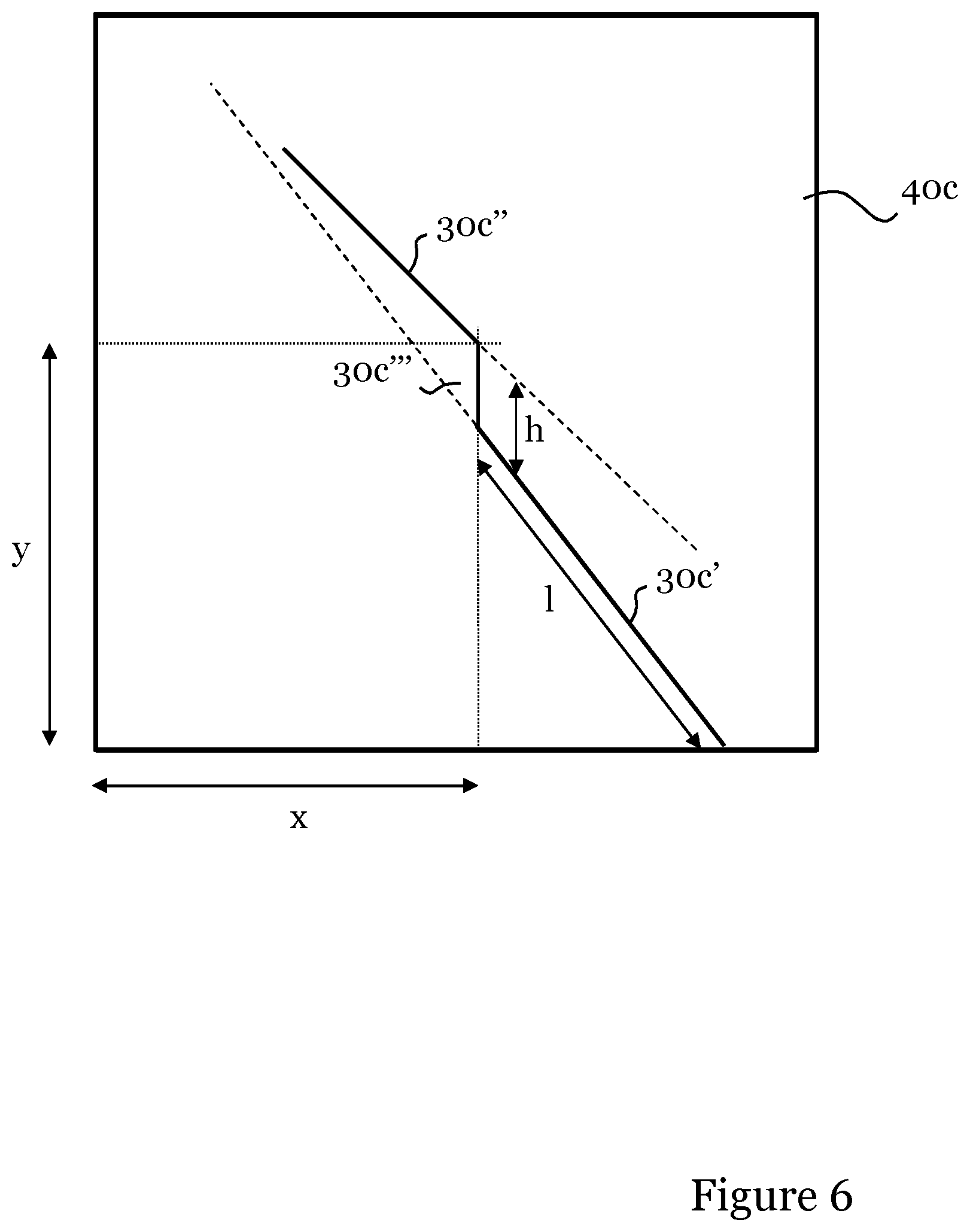
[0072] FIG. 6 illustrates the image 40c captured by the camera 123 of the robotic device 100 upon encountering the elevation 37.
[0073] In this image, the laser beam 30c will fall onto the floor 31 in front of the robotic device 100 and further onto the edge of the rug causing the elevation 36 and the upper side 37 or the rug. This will result in three segments 30c', 30c'' and 30c''' visible in the captured image 40c.
[0074] From the captured image 40c of FIG. 6, the robotic device 100 again detects a luminous section caused by the emitted laser line 30c, and identifies the first segment 30c', the second segment 30c'', and a further a third segment 30c''' linking the first and second segments, which represents the detected luminous section.
[0075] Now, after having identified the first and the second segment 30c', 30c'', the robotic device 100 detects, from a positional relationship between the identified first and second segment 30c', 30c'', a difference in level of the surface 31.
[0076] In a basic embodiment, which advantageously can be implemented for less complex robotic devices, the difference in level of the floor 31 over which the robotic device 100 moves is detected by concluding from the 2D image 40b that the first and second segment 30c', 30c'' are linked by a third segment 30c'''
[0077] If such a linking segment 30c''' between the first and the second segment 30c', 30c'' is present in the captured image 40c, the robotic device 100 concludes that the (upper) side 37 of the rug is located at a higher level than the floor 31. However, if such a method is used, the robotic device 100 only knows that there is difference in level, but cannot assess an actual height.
[0078] In another embodiment, the robotic device 100 determines if the second segment 30c'' is located vertically above the first segment 30c' in which case the difference in level constitutes an elevation.
[0079] In a further embodiment, again with reference to FIG. 6, the robotic device 100 determines a distance l to the elevation 36 and a height h of the elevation 36, as has been described hereinabove.
[0080] This information may advantageously be used for sectionalizing an area to be cleaned. For instance, the robotic device 100 may determine that it should finish cleaning the floor of the room in which it currently is located before moving up on the rug. Alternatively, in case the elevation is caused by a doorstep, the robotic device 100 may determine that the room is to be finished before it crosses the doorstep into the next room.
[0081] It may further be envisaged that the robotic device 100 does not ascend the rug/doorstep at all after having determined its height h. Assuming for instance that the height h of an elevation exceeds a predetermined level threshold value; this may indicate that e.g. a doorstep is too high to ascend in order to avoid having the robot being stuck on the doorstep.
[0082] The camera 123 of the robotic cleaning device 100 is controlled by a controller such as a microprocessor to capture and record images from which the controller creates a representation or layout of the surroundings that the robotic cleaning device 100 is operating in, by extracting feature points from the images representing detected objects and by measuring the distance from the robotic cleaning device 100 to these objects, as well as the heights of the objects using the method of the invention as has been discussed. while the robotic cleaning device 100 is moving across the surface to be cleaned. Thus, the controller derives positional data of the robotic cleaning device 100 with respect to the surface to be cleaned from the detected objects of the recorded images, generates a 3D representation of the surroundings from the derived positional data and controls driving motors to move the robotic cleaning device 100 across the surface to be cleaned in accordance with the generated 3D representation and navigation information supplied to the robotic cleaning device 100 such that the surface to be cleaned can be autonomously navigated by taking into account the generated 3D representation. Since the derived positional data will serve as a foundation for the navigation of the robotic cleaning device, it is important that the positioning is correct; the robotic device will otherwise navigate according to a "map" of its surroundings that is misleading.
[0083] The 3D representation generated from the images recorded by the camera 123 thus facilitates detection of obstacles in the form of walls, floor lamps, table legs, around which the robotic cleaning device must navigate as well as rugs, carpets, doorsteps, etc., that the robotic cleaning device 100 must traverse. The robotic cleaning device 100 is hence configured to learn about its environment or surroundings by operating/cleaning.
[0084] The robotic cleaning device 100 may advantageously add indications of detected ledges and elevations to the created representation of its surroundings. Thus, by adding to the created representation an indication of e.g. the ledge 34, it is possible for the robotic cleaning device to plan a cleaning path to be traversed well in advance and further to move very close to, and along, the ledge 34 since it is included in the representation of the surroundings of the robotic cleaning device 100.
[0085] Even though it is envisaged that the invention may be performed by a variety of appropriate robotic cleaning devices being equipped with sufficient processing intelligence, FIG. 7 shows a robotic cleaning device 100 according to an embodiment of the present invention in a bottom view, i.e. the bottom side of the robotic cleaning device is shown. The arrow indicates the forward direction of the robotic cleaning device 100 being illustrated in the form of a robotic vacuum cleaner.
[0086] The robotic cleaning device 100 comprises a main body 111 housing components such as a propulsion system comprising driving means in the form of two electric wheel motors 115a, 115b for enabling movement of the driving wheels 112, 113 such that the cleaning device can be moved over a surface to be cleaned. Each wheel motor 115a, 115b is capable of controlling the respective driving wheel 112, 113 to rotate independently of each other in order to move the robotic cleaning device 100 across the surface to be cleaned. A number of different driving wheel arrangements, as well as various wheel motor arrangements, can be envisaged. It should be noted that the robotic cleaning device may have any appropriate shape, such as a device having a more traditional circular-shaped main body, or a triangular-shaped main body. As an alternative, a track propulsion system may be used or even a hovercraft propulsion system. The propulsion system may further be arranged to cause the robotic cleaning device 100 to perform any one or more of a yaw, pitch, translation or roll movement.
[0087] A controller 116 such as a microprocessor controls the wheel motors 115a, 115b to rotate the driving wheels 112, 113 as required in view of information received from an obstacle detecting device (not shown in FIG. 7) for detecting obstacles in the form of walls, floor lamps, table legs, around which the robotic cleaning device must navigate. The obstacle detecting device may be embodied in the form of a 3D sensor system registering its surroundings, implemented by means of e.g. a 3D camera, a camera in combination with lasers, a laser scanner, etc. for detecting obstacles and communicating information about any detected obstacle to the microprocessor 116. The microprocessor 116 communicates with the wheel motors 115a, 115b to control movement of the wheels 112, 113 in accordance with information provided by the obstacle detecting device such that the robotic cleaning device 100 can move as desired across the surface to be cleaned.
[0088] Further, the main body 111 may optionally be arranged with a cleaning member 117 for removing debris and dust from the surface to be cleaned in the form of a rotatable brush roll arranged in an opening 118 at the bottom of the robotic cleaner 100. Thus, the rotatable brush roll 117 is arranged along a horizontal axis in the opening 118 to enhance the dust and debris collecting properties of the robotic cleaning device 100. In order to rotate the brush roll 117, a brush roll motor 119 is operatively coupled to the brush roll to control its rotation in line with instructions received from the controller 116.
[0089] Moreover, the main body 111 of the robotic cleaner 100 comprises a suction fan 20 creating an air flow for transporting debris to a dust bag or cyclone arrangement (not shown) housed in the main body via the opening 118 in the bottom side of the main body 111. The suction fan 120 is driven by a fan motor 121 communicatively connected to the controller 116 from which the fan motor 121 receives instructions for controlling the suction fan 120. It should be noted that a robotic cleaning device having either one of the rotatable brush roll 117 and the suction fan 20 for transporting debris to the dust bag can be envisaged. A combination of the two will however enhance the debris-removing capabilities of the robotic cleaning device 100.
[0090] The main body 111 of the robotic cleaning device 100 may further equipped with an inertia measurement unit (IMU) 124, such as e.g. a gyroscope and/or an accelerometer and/or a magnetometer or any other appropriate device for measuring displacement of the robotic cleaning device 100 with respect to a reference position, in the form of e.g. orientation, rotational velocity, gravitational forces, etc. A three-axis gyroscope is capable of measuring rotational velocity in a roll, pitch and yaw movement of the robotic cleaning device 100. A three-axis accelerometer is capable of measuring acceleration in all directions, which is mainly used to determine whether the robotic cleaning device is bumped or lifted or if it is stuck (i.e. not moving even though the wheels are turning). The robotic cleaning device 100 further comprises encoders (not shown in FIG. 7) on each drive wheel 112, 113 which generate pulses when the wheels turn. The encoders may for instance be magnetic or optical. By counting the pulses at the controller 116, the speed of each wheel 112, 113 can be determined. By combining wheel speed readings with gyroscope information, the controller 116 can perform so called dead reckoning to determine position and heading of the cleaning device 100.
[0091] The main body 111 may further be arranged with a rotating side brush 114 adjacent to the opening 118, the rotation of which could be controlled by the drive motors 115a, 115b, the brush roll motor 119, or alternatively a separate side brush motor (not shown). Advantageously, the rotating side brush 114 sweeps debris and dust such from the surface to be cleaned such that the debris ends up under the main body 111 at the opening 118 and thus can be transported to a dust chamber of the robotic cleaning device. Further advantageous is that the reach of the robotic cleaning device 100 will be improved, and e.g. corners and areas where a floor meets a wall are much more effectively cleaned. As is illustrated in FIG. 7, the rotating side brush 114 rotates in a direction such that it sweeps debris towards the opening 118 such that the suction fan 20 can transport the debris to a dust chamber. The robotic cleaning device 100 may comprise two rotating side brushes arranged laterally on each side of, and adjacent to, the opening 118.
[0092] With further reference to FIG. 7, the controller/processing unit 116 embodied in the form of one or more microprocessors is arranged to execute a computer program 125 downloaded to a suitable storage medium 126 associated with the microprocessor, such as a Random Access Memory (RAM), a Flash memory or a hard disk drive. The controller 116 is arranged to carry out a method according to embodiments of the present invention when the appropriate computer program 125 comprising computer-executable instructions is downloaded to the storage medium 126 and executed by the controller 116. The storage medium 126 may also be a computer program product comprising the computer program 125. Alternatively, the computer program 125 may be transferred to the storage medium 126 by means of a suitable computer program product, such as a digital versatile disc (DVD), compact disc (CD) or a memory stick. As a further alternative, the computer program 125 may be downloaded to the storage medium 126 over a wired or wireless network. The controller 116 may alternatively be embodied in the form of a digital signal processor (DSP), an application specific integrated circuit (ASIC), a field-programmable gate array (FPGA), a complex programmable logic device (CPLD), etc.
[0093] As has been mentioned, by measuring a difference in level of the surface in front of the robotic device 100, it is advantageously possible to timely plan how the robotic device 100 should move for performing a cleaning programme.
[0094] With reference to FIG. 7, by detecting height of objects or surfaces in front of the robotic cleaning device 100, for instance a thick rug, the robot 100 may be controlled to move along the periphery of the rug thereby making efficient use of the side brush 114. After having cleaned along the periphery of the rug, the robotic cleaning device 100 may move up onto the rug, where it typically would refrain from using the side brush 114. Instead, the robot 100 could alternately rotate the rotatable brush roll 117 in a forward and backward direction to avoid having the fibers of the rug being entangled in the brush roll 117. Hence, the movement of the brush roll 117 and any side brush(es) 114 can advantageously be controlled by taking into account the determined height of the surfaces and objects in front of the robotic cleaning device 100. FIG. 8 shows a front view of the robotic cleaning device 100 of FIG. 7 in an embodiment of the present invention illustrating the previously mentioned obstacle detecting device in the form of a 3D sensor system comprising at least a camera 123 and a first and a second line laser 127, 128, which may be horizontally or vertically oriented line lasers. Further shown is the controller 116, the main body 111, the driving wheels 112, 113, and the rotatable brush roll 117 previously discussed with reference to FIG. 6. The controller 116 is operatively coupled to the camera 123 for recording images of a vicinity of the robotic cleaning device 100. The first and second line lasers 127, 128 may preferably be vertical line lasers and are arranged lateral of the camera 123 and configured to illuminate a height and a width that is greater than the height and width of the robotic cleaning device 100. Further, the angle of the field of view of the camera 123 is preferably smaller than the space illuminated by the first and second line lasers 127, 128. The camera 123 is controlled by the controller 116 to capture and record a plurality of images per second. Data from the images is extracted by the controller 116 and the data is typically saved in the memory 126 along with the computer program 125.
[0095] The first and second line lasers 127, 128 are typically arranged on a respective side of the camera 123 along an axis being perpendicular to an optical axis of the camera. Further, the line lasers 127, 128 are directed such that their respective laser beams intersect within the field of view of the camera 123. Typically, the intersection coincides with the optical axis of the camera 123.
[0096] The first and second line laser 127, 128 are configured to scan, preferably in a vertical orientation, the vicinity of the robotic cleaning device 100, normally in the direction of movement of the robotic cleaning device 100. The first and second line lasers 127, 128 are configured to send out laser beams, which illuminate furniture, walls and other objects of e.g. a room to be cleaned. The camera 123 is controlled by the controller 116 to capture and record images from which the controller 116 creates a representation or layout of the surroundings that the robotic cleaning device 100 is operating in, by extracting features from the images and by measuring the distance covered by the robotic cleaning device 100, while the robotic cleaning device 100 is moving across the surface to be cleaned. Thus, the controller 116 derives positional data of the robotic cleaning device 100 with respect to the surface to be cleaned from the recorded images, generates a 3D representation of the surroundings from the derived positional data and controls the driving motors 115a, 115b to move the robotic cleaning device across the surface to be cleaned in accordance with the generated 3D representation and navigation information supplied to the robotic cleaning device 100 such that the surface to be cleaned can be navigated by taking into account the generated 3D representation. Since the derived positional data will serve as a foundation for the navigation of the robotic cleaning device, it is important that the positioning is correct; the robotic device will otherwise navigate according to a "map" of its surroundings that is misleading.
[0097] The 3D representation generated from the images recorded by the 3D sensor system thus facilitates detection of obstacles in the form of walls, floor lamps, table legs, around which the robotic cleaning device must navigate as well as rugs, carpets, doorsteps, etc., that the robotic cleaning device 100 must traverse. The robotic cleaning device 100 is hence configured to learn about its environment or surroundings by operating/cleaning.
[0098] Hence, the 3D sensor system comprising the camera 123 and the first and second vertical line lasers 127, 128 is arranged to record images of a vicinity of the robotic cleaning from which objects/obstacles may be detected. The controller 116 is capable of positioning the robotic cleaning device 100 with respect to the detected obstacles and hence a surface to be cleaned by deriving positional data from the recorded images. From the positioning, the controller 116 controls movement of the robotic cleaning device 100 by means of controlling the wheels 112, 113 via the wheel drive motors 115a, 115b, across the surface to be cleaned.
[0099] The derived positional data facilitates control of the movement of the robotic cleaning device 100 such that cleaning device can be navigated to move very close to an object, and to move closely around the object to remove debris from the surface on which the object is located. Hence, the derived positional data is utilized to move flush against the object, being e.g. a chair, a table, a sofa, a thick rug or a wall. Typically, the controller 116 continuously generates and transfers control signals to the drive wheels 112, 113 via the drive motors 115a, 115b such that the robotic cleaning device 100 is navigated close to the object.
[0100] It should further be noted that while the embodiments of the invention has been discussed in the context of using a camera and one or two line lasers for illuminating a surface over which the robotic cleaning device 100 moves, it would further be possible to use known 3D sensors utilizing time of flight measurements of an image being completely illuminated. With such a time of flight 3D sensor, the distance in a captured image would be determined for each pixel and distances to detected objects may be determined in line with the above.
[0101] The invention has mainly been described above with reference to a few embodiments. However, as is readily appreciated by a person skilled in the art, other embodiments than the ones disclosed above are equally possible within the scope of the invention, as defined by the appended patent claims.
* * * * *
D00000
D00001
D00002
D00003
D00004
D00005
D00006
D00007
D00008
D00009
D00010
XML
uspto.report is an independent third-party trademark research tool that is not affiliated, endorsed, or sponsored by the United States Patent and Trademark Office (USPTO) or any other governmental organization. The information provided by uspto.report is based on publicly available data at the time of writing and is intended for informational purposes only.
While we strive to provide accurate and up-to-date information, we do not guarantee the accuracy, completeness, reliability, or suitability of the information displayed on this site. The use of this site is at your own risk. Any reliance you place on such information is therefore strictly at your own risk.
All official trademark data, including owner information, should be verified by visiting the official USPTO website at www.uspto.gov. This site is not intended to replace professional legal advice and should not be used as a substitute for consulting with a legal professional who is knowledgeable about trademark law.