Objective Optical System For Endoscope, Endoscope, And Image Pickup Unit
KAMO; Yuji ; et al.
U.S. patent application number 16/680452 was filed with the patent office on 2020-03-12 for objective optical system for endoscope, endoscope, and image pickup unit. This patent application is currently assigned to OLYMPUS CORPORATION. The applicant listed for this patent is OLYMPUS CORPORATION. Invention is credited to Yuji KAMO, Yoshifumi TSUJI.
| Application Number | 20200081240 16/680452 |
| Document ID | / |
| Family ID | 64735650 |
| Filed Date | 2020-03-12 |


| United States Patent Application | 20200081240 |
| Kind Code | A1 |
| KAMO; Yuji ; et al. | March 12, 2020 |
OBJECTIVE OPTICAL SYSTEM FOR ENDOSCOPE, ENDOSCOPE, AND IMAGE PICKUP UNIT
Abstract
An objective optical system for endoscope includes a first lens having a negative refractive power, a second lens having a positive refractive power, an aperture stop, a third lens having a positive refractive power, a fourth lens having a positive refractive power, a fifth lens having a negative refractive power, and a sixth lens having a positive refractive power. The second lens is a meniscus lens having a convex surface directed toward an image side and the third lens is a meniscus lens having a convex surface directed toward the image side. A cemented lens having a positive refractive power is formed by the fourth lens and the fifth lens. The sixth lens is cemented to an image sensor, and the following conditional expression (1''') is satisfied: 1.ltoreq.(r3f+r3r)/(r3f-r3r).ltoreq.5 (1''').
| Inventors: | KAMO; Yuji; (Tokyo, JP) ; TSUJI; Yoshifumi; (Tokyo, JP) | ||||||||||
| Applicant: |
|
||||||||||
|---|---|---|---|---|---|---|---|---|---|---|---|
| Assignee: | OLYMPUS CORPORATION Tokyo JP |
||||||||||
| Family ID: | 64735650 | ||||||||||
| Appl. No.: | 16/680452 | ||||||||||
| Filed: | November 11, 2019 |
Related U.S. Patent Documents
| Application Number | Filing Date | Patent Number | ||
|---|---|---|---|---|
| PCT/JP2018/009237 | Mar 9, 2018 | |||
| 16680452 | ||||
| Current U.S. Class: | 1/1 |
| Current CPC Class: | A61B 1/00 20130101; G02B 23/26 20130101; G02B 23/2484 20130101; A61B 1/05 20130101; G02B 15/1465 20190801; G02B 23/243 20130101; G02B 23/2446 20130101 |
| International Class: | G02B 23/24 20060101 G02B023/24; G02B 23/26 20060101 G02B023/26 |
Foreign Application Data
| Date | Code | Application Number |
|---|---|---|
| Jun 22, 2017 | JP | 2017-122540 |
Claims
1. An objective optical system for endoscope, comprising in order from an object side: a first lens having a negative refractive power, a second lens having a positive refractive power, an aperture stop, a third lens having a positive refractive power, a fourth lens having a positive refractive power, a fifth lens having a negative refractive power, and a sixth lens having a positive refractive power, wherein the second lens is a meniscus lens having a convex surface directed toward an image side, the third lens is a meniscus lens having a convex surface directed toward the image side, a cemented lens having a positive refractive power is formed by the fourth lens and the fifth lens, the sixth lens is cemented to an image sensor, and the following conditional expression (1''') is satisfied: 1.ltoreq.(r3f+r3r)/(r3f-r3r).ltoreq.5 (1''') where, r3f denotes a radius of curvature of an object-side surface of the third lens, and r3r denotes a radius of curvature of an image-side surface of the third lens.
2. The objective optical system for endoscope according to claim 1, wherein the following conditional expression (2) is satisfied: -20.ltoreq.r3f/r4f.ltoreq.-0.5 (2) where, r3f denotes the radius of curvature of the object-side surface of the third lens, and r4f denotes a radius of curvature of an object-side surface of the fourth lens.
3. The objective optical system for endoscope according to claim 1, wherein the following conditional expression (3) is satisfied: -1.ltoreq.r6f/r3f.ltoreq.-0.02 (3) where, r6f denotes a radius of curvature of an object-side surface of the sixth lens, and r3f denotes the radius of curvature of the object-side surface of the third lens.
4. The objective optical system for endoscope according to claim 1, wherein the following conditional expression (4) is satisfied: -0.7.ltoreq.f1/f4.ltoreq.-0.3 (4) where, f1 denotes a focal length of the first lens, and f4 denotes a focal length of the fourth lens.
5. The objective optical system for endoscope according to claim 1, wherein the following conditional expression (5) is satisfied: 0.6.ltoreq.r3r/r4r.ltoreq.1.7 (5) where, r3r denotes the radius of curvature of the image-side surface of the third lens, and r4r denotes a radius of curvature of an image-side surface of the fourth lens.
6. The objective optical system for endoscope according to claim 1, wherein the following conditional expression (6) is satisfied: -0.7.ltoreq.(r3r+r4f)/(r3r-r4f).ltoreq.-0.1 (6) where, r3r denotes the radius of curvature of the image-side surface of the third lens, and r4f denotes a radius of curvature of the object-side surface of the fourth lens.
7. The objective optical system for endoscope according to claim 1, wherein the following conditional expression (7) is satisfied: 0.05.ltoreq.(r4f+r4r)/(r4f-r4r).ltoreq.0.33 (7) where, r4f denotes a radius of curvature of the object-side surface of the fourth lens, and r4r denotes a radius of curvature of the image-side surface of the fourth lens.
8. The objective optical system for endoscope according to claim 1, wherein the following conditional expression (8) is satisfied: -1.45.ltoreq.f3/f5.ltoreq.-1 (8) where, f3 denotes a focal length of the third lens, and f5 denotes a focal length of the fifth lens.
9. The objective optical system according to claim 1, wherein the following conditional expressions (9-1) and (9-2) are satisfied: -2.5.ltoreq.r6f/r3r.ltoreq.-0.65 (9-1) 1.5.ltoreq.f2/f3.ltoreq.3 (9-2) where, r6f denotes a radius of curvature of an object-side surface of the sixth lens, r3r denotes the radius of curvature of the image-side surface of the third lens, f2 denotes a focal length of the second lens, and f3 denotes a focal length of the third lens.
10. The objective optical system for endoscope according to claim 1, wherein the following conditional expressions (10-1) and (10-2) are satisfied: -0.25.ltoreq.(r5f+r6f)/(r5f-r6f).ltoreq.0.2 (10-1) 1.ltoreq.f2/f6.ltoreq.1.6 (10-2) where, r5f denotes a radius of curvature of an object-side surface of the fifth lens, r6f denotes a radius of curvature of the object-side surface of the sixth lens, f2 denotes a focal length of the second lens, and f6 denotes a focal length of the sixth lens.
11. The objective optical system for endoscope according to claim 1, wherein the following conditional expression (11) is satisfied: -15.ltoreq.f45/f.ltoreq.-3 (11) where, f45 denotes a focal length of the cemented lens, and f1 denotes a focal length of the first lens.
12. An endoscope comprising: an objective optical system disposed on the distal end portion of an insertion portion which is inserted to an object under examination, and an image sensor disposed on the distal end and receives light from an image of an object formed by the objective optical system, wherein the objective optical system comprising in order from an object side, a first lens having a negative refractive power, a second lens having a positive refractive power, an aperture stop, a third lens having a positive refractive power, a fourth lens having a positive refractive power, a fifth lens having a negative refractive power, and a sixth lens having a positive refractive power, wherein the second lens is a meniscus lens having a convex surface directed toward an image side, the third lens is a meniscus lens having a convex surface directed toward the image side, a cemented lens having a positive refractive power is formed by the fourth lens and the fifth lens, the sixth lens is cemented to the image sensor, and the following conditional expression (1''') is satisfied: 1.ltoreq.(r3f+r3r)/(r3f-r3r).ltoreq.5 (1''') where, r3f denotes a radius of curvature of an object-side surface of the third lens, and r3r denotes a radius of curvature of an image-side surface of the third lens.
13. An image pickup unit comprising: an objective optical system which forms an image of an object, and an image sensor which receives light from the image of the object formed by the objective optical system, wherein the objective optical system comprising in order from an object side, a first lens having a negative refractive power, a second lens having a positive refractive power, an aperture stop, a third lens having a positive refractive power, a fourth lens having a positive refractive power, a fifth lens having a negative refractive power, and a sixth lens having a positive refractive power, wherein the second lens is a meniscus lens having a convex surface directed toward an image side, the third lens is a meniscus lens having a convex surface directed toward the image side, a cemented lens having a positive refractive power is formed by the fourth lens and the fifth lens, the sixth lens is cemented to the image sensor, and the following conditional expression (1''') is satisfied: 1.ltoreq.(r3f+r3r)/(r3f-r3r).ltoreq.5 (1''') where, r3f denotes a radius of curvature of an object-side surface of the third lens, and r3r denotes a radius of curvature of an image-side surface of the third lens.
Description
CROSS-REFERENCE TO RELATED APPLICATION
[0001] The present application is a continuation application of PCT/JP2018/009237 filed on Mar. 9, 2018 which is based upon and claims the benefit of priority from Japanese Patent Application No. 2017-122540 filed on Jun. 22, 2017; the entire contents of which are incorporated herein by reference.
BACKGROUND
Technical Field
[0002] The present disclosure relates to an objective optical system such as an objective optical system for endoscope which can be used in an endoscope apparatus to be used in a medical field and an industrial field, an endoscope, and an image pickup unit.
Description of the Related Art
[0003] An endoscope is an apparatus that has been widely used in the medical field and the industrial field. Particularly in the medical field, endoscopes have been used for diagnosis and treatment of parts to be observed. Images achieved by an endoscope inserted into a body cavity are used for the diagnosis and treatment.
[0004] In an objective optical system for endoscope, by setting an appropriate F-number and a focusing position, a focused image from a near point up to a far point is formed. Moreover, in an objective optical system, small-sizing of a lens diameter and shortening of an overall length of the optical system have been carried out. By doing so, it is possible to make an insertion portion thin. As a result, it is possible to reduce pain at the time of insertion and to realize an insertion portion that can be turned in a small radius. In recent years, endoscopes of even higher image quality and smaller size have been sought.
[0005] As objective optical systems having a small size, objective optical systems described in Japanese Patent No. 3723637 Publication, International Unexamined Patent Application Publication No. 2013/002019, International Unexamined Patent Application Publication No. 2011/145505, Japanese Patent Application Laid-open Publication No. 2001-083400, Japanese Patent Application Laid-open Publication No. Hei 6-222263, Japanese Patent No. 2596810 Publication, and Japanese Patent No. 5927368 Publication are available.
[0006] In Japanese Patent No. 3723637 Publication, an image pickup lens has been disclosed. The image pickup lens includes in order from an object side, a negative lens, a positive lens, an aperture stop, a positive lens, a cemented lens in which a negative lens and a positive lens are cemented, and a positive lens.
[0007] In International Unexamined Patent Application Publication No. 2013/002019, an endoscope objective optical system has been disclosed. The endoscope objective optical system includes in order from an object side, a negative lens, a positive lens, a meniscus lens that can be inserted and removed, an aperture stop, a positive lens, and a positive lens. The positive lens positioned nearest to an image is cemented to a cover glass of an image sensor.
[0008] In International Unexamined Patent Application Publication No. 2011/145505, an endoscope objective lens unit has been disclosed. The endoscope objective lens unit includes in order from an object side, a negative lens, a positive lens, an aperture stop, a positive lens, and a cemented lens in which a positive lens and a negative lens are cemented.
[0009] In Japanese Patent Application Laid-open Publication No. 2001-083400, an image pickup optical system has been disclosed. The image pickup optical system includes in order from an object side, a negative lens, a positive lens, an aperture stop, a positive lens, a cemented lens in which a positive lens and a negative lens are cemented, and a positive lens. The positive lens positioned nearest to an image is cemented to a cover glass of an image sensor.
[0010] In Japanese Patent Application Laid-open Publication No. Hei 6-222263, an endoscope objective lens has been disclosed. The endoscope objective lens includes in order from an object side, a negative lens, a positive lens, an aperture stop, a positive lens, a cemented lens in which a positive lens and a negative lens are cemented, and a positive lens. The positive lens positioned nearest to an image is cemented to a cover glass of an image sensor.
[0011] In Japanese Patent No. 2596810 Publication, an optical system for endoscope has been disclosed. The optical system for endoscope includes in order from an object side, a negative lens, a positive lens, an aperture stop, a positive lens, a cemented lens in which a positive lens and a negative lens are cemented, and a positive lens. The positive lens positioned nearest to an image is cemented to a cover glass of an image sensor.
[0012] In Japanese Patent No. 5927368 Publication, an endoscope objective optical system has been disclosed. The endoscope objective optical system includes in order from an object side, a negative lens, a positive lens, an aperture stop, a positive lens, a cemented lens in which a positive lens and a negative lens are cemented, and a positive lens. The positive lens positioned nearest to an image is cemented to a cover glass of an image sensor.
SUMMARY
[0013] An objective optical system for endoscope according to at least some embodiments of the present disclosure includes in order from an object side,
[0014] a first lens having a negative refractive power,
[0015] a second lens having a positive refractive power,
[0016] an aperture stop,
[0017] a third lens having a positive refractive power,
[0018] a fourth lens having a positive refractive power,
[0019] a fifth lens having a negative refractive power, and
[0020] a sixth lens having a positive refractive power, wherein
[0021] the second lens is a meniscus lens having a convex surface directed toward an image side,
[0022] the third lens is a meniscus lens having a convex surface directed toward the image side,
[0023] a cemented lens having a positive refractive power is formed by the fourth lens and the fifth lens,
[0024] the sixth lens is cemented to an image sensor, and
[0025] the following conditional expression (1''') is satisfied:
1.ltoreq.(r3f+r3r)/(r3f-r3r).ltoreq.5 (1''')
[0026] where,
[0027] r3f denotes a radius of curvature of an object-side surface of the third lens, and
[0028] r3r denotes a radius of curvature of an image-side surface of the third lens.
[0029] An endoscope according to at least some embodiments of the present disclosure includes:
[0030] an objective optical system disposed on the distal end portion of an insertion portion which is inserted to an object under examination, and
[0031] an image sensor disposed on the distal end and receives light from an image of an object formed by the objective optical system, wherein
[0032] the objective optical system includes in order from an object side,
[0033] a first lens having a negative refractive power,
[0034] a second lens having a positive refractive power,
[0035] an aperture stop,
[0036] a third lens having a positive refractive power,
[0037] a fourth lens having a positive refractive power,
[0038] a fifth lens having a negative refractive power, and
[0039] a sixth lens having a positive refractive power, wherein
[0040] the second lens is a meniscus lens having a convex surface directed toward an image side,
[0041] the third lens is a meniscus lens having a convex surface directed toward the image side,
[0042] a cemented lens having a positive refractive power is formed by the fourth lens and the fifth lens,
[0043] the sixth lens is cemented to the image sensor, and the following conditional expression (1''') is satisfied:
1.ltoreq.(r3f+r3r)/(r3f-r3r).ltoreq.5 (1''')
[0044] where,
[0045] r3f denotes a radius of curvature of an object-side surface of the third lens, and
[0046] r3r denotes a radius of curvature of an image-side surface of the third lens.
[0047] An image pickup unit according to at least some embodiments of the present disclosure includes:
[0048] an objective optical system which forms an image of an object, and
[0049] an image sensor which receives light from the image of the object formed by the objective optical system, wherein
[0050] the objective optical system includes in order from an object side,
[0051] a first lens having a negative refractive power,
[0052] a second lens having a positive refractive power,
[0053] an aperture stop,
[0054] a third lens having a positive refractive power,
[0055] a fourth lens having a positive refractive power,
[0056] a fifth lens having a negative refractive power, and
[0057] a sixth lens having a positive refractive power, wherein
[0058] the second lens is a meniscus lens having a convex surface directed toward an image side,
[0059] the third lens is a meniscus lens having a convex surface directed toward the image side,
[0060] a cemented lens having a positive refractive power is formed by the fourth lens and the fifth lens,
[0061] the sixth lens is cemented to the image sensor, and
[0062] the following conditional expression (1''') is satisfied:
1.ltoreq.(r3f+r3r)/(r3f-r3r).ltoreq.5 (1''')
[0063] where,
[0064] r3f denotes a radius of curvature of an object-side surface of the third lens, and
[0065] r3r denotes a radius of curvature of an image-side surface of the third lens.
BRIEF DESCRIPTION OF THE DRAWINGS
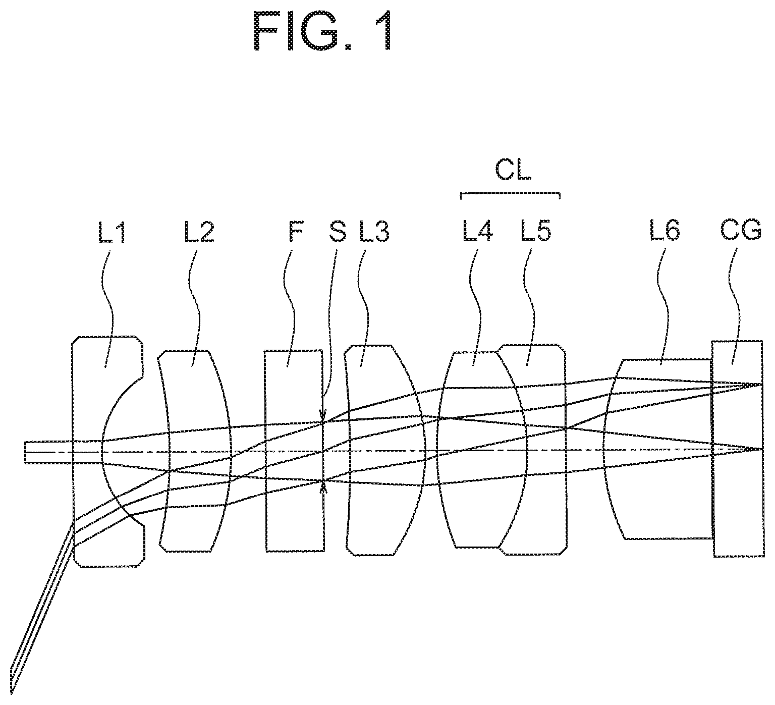
[0066] FIG. 1 is a cross-sectional view showing a specific arrangement of an objective optical system for endoscope according to the present embodiment;
[0067] FIG. 2A and FIG. 2B are diagrams showing an appearance of an occurrence of flare;
[0068] FIG. 3A is a cross-sectional view of an objective optical system for endoscope of an example 1, and FIG. 3B, FIG. 3C, FIG. 3D, and FIG. 3E are aberration diagrams;
[0069] FIG. 4A is a cross-sectional view of an objective optical system for endoscope of an example 2, and FIG. 4B, FIG. 4C, FIG. 4D, and FIG. 4E are aberration diagrams.
[0070] FIG. 5A is a cross-sectional view of an objective optical system for endoscope of an example 3, and FIG. 5B, FIG. 5C, FIG. 5D, and FIG. 5E are aberration diagrams.
DETAILED DESCRIPTION
[0071] Reasons for adopting such arrangements and effects thereof in an objective optical system for endoscope according to the present embodiment, will be described below by referring to the accompanying diagrams. However, the present disclosure is not restricted to the following embodiment.
[0072] An objective optical system for endoscope according to the present embodiment includes in order from an object side, a first lens having a negative refractive power, a second lens having a positive refractive power, an aperture stop, a third lens having a positive refractive power, a fourth lens having a positive refractive power, a fifth lens having a negative refractive power, and a sixth lens having a positive refractive power, wherein the second lens is a meniscus lens having a convex surface directed toward an image side, the third lens is a meniscus lens having a convex surface directed toward the image side, a cemented lens having a positive refractive power is formed by the fourth lens and the fifth lens, the sixth lens is cemented to an image sensor, and the following conditional expression (1) is satisfied:
0.55.ltoreq.(r3f+r3r)/(r3f-r3r).ltoreq.5 (1)
[0073] where,
[0074] r3f denotes a radius of curvature of an object-side surface of the third lens, and
[0075] r3r denotes a radius of curvature of an image-side surface of the third lens.
[0076] The objective optical system for endoscope according to the present embodiment will be described below. FIG. 1 is a cross-sectional view showing the objective optical system for endoscope according to the present embodiment. As shown in FIG. 1, the objective optical system for endoscope according to the present embodiment includes in order from an object side, a first lens L1 having a negative refractive power, a second lens L2 having a positive refractive power, an aperture stop S, a third lens L3 having a positive refractive power, a fourth lens L4 having a positive refractive power, a fifth lens L5 having a negative refractive power, and a sixth lens L6 having a positive refractive power.
[0077] The second lens L2 is a meniscus lens having a convex surface directed toward an image side. The third lens L3 is a meniscus lens having a convex surface directed toward the image side. A cemented lens CL having a positive refractive power is formed by the fourth lens L4 and the fifth lens L5. The sixth lens L6 is cemented to a cover glass CG. The cover glass CG is a cover glass of an image sensor. The sixth lens 6, instead of being cemented via the cover glass CG, may be cemented directly to an image pickup surface of the image sensor.
[0078] A plane parallel plate F is disposed between the second lens L2 and the third lens L3. It is possible to dispose the plane parallel plate F at an arbitrary position in the objective optical system for endoscope. The cover glass CG is disposed on the image side of the sixth lens L6. The cover glass CG is a cover glass of an image sensor. The image sensor (not shown in the diagram) is disposed on the image side of the cover glass CG. An image-side surface of the cover glass CG is an image plane. The image pickup surface of the image sensor coincides with the image-side surface of the cover glass CG.
[0079] The aperture stop S is disposed between the second lens L2 and the third lens L3. More specifically, the aperture stop S is positioned on an image-side surface of the plane parallel plate F.
[0080] In an endoscope, generally, it is necessary to able to observe over a wide range. Moreover, since insertion of an insertion portion into a body is carried out, it is necessary that an outer diameter of the insertion portion is thin. For such reason, in an objective optical system for endoscope, an outer diameter of an optical system, and particularly, an outer diameter of a lens positioned nearest to an object has to be made small.
[0081] For such reason, in the objective optical system for endoscope according to the present embodiment, as a type of the optical system, an optical system of a retro focus type is adopted. For realizing the optical system of retro focus type, in the objective optical system for endoscope according to the present embodiment, the first lens L1 having a negative refractive power is disposed nearest to the object. Accordingly, a negative refractive power necessary for an optical system of retro focus type has been secured.
[0082] The second lens L2 is disposed on the image side of the first lens L1. The second lens L2 is a meniscus lens having a convex surface directed toward the image side. By making such arrangement, an aberration occurred in the first lens L1 having a negative refractive power is corrected in the second lens L2.
[0083] The aperture stop S is positioned on the image side of the second lens L2. The third lens L3 is disposed on the image side of the aperture stop S. The third lens L3 is a meniscus lens having a convex surface directed toward the image side. The third lens L3 mainly contributes to image formation. Therefore, in the third lens L3, the positive refractive power necessary for image formation is secured.
[0084] The cemented lens CL is disposed on the image side of the third lens L3. The cemented lens CL includes the fourth lens L4 and the fifth lens L5. On the image side of the third lens L3, a height of a light ray reaching a peripheral portion of an image becomes high. It is easy to carry out correction a chromatic aberration at a location at which the height of a light ray is high. Therefore, correction of the chromatic aberration is carried out by disposing the cemented lens CL on the image side of the third lens L3.
[0085] Moreover, by making the refractive power of the cemented lens CL a positive refractive power, the positive refractive power necessary for image formation is secured even in the cemented lens CL. In this case, since it is possible to share the positive refractive power necessary for image formation by the third lens L3 and the cemented lens CL, it is possible to suppress both an occurrence of aberration in the third lens L3 and an occurrence of aberration in the cemented lens CL.
[0086] The sixth lens L6 is disposed on the image side of the cemented lens CL. The sixth lens L6 is disposed near an image plane.
[0087] It is possible to combine the objective optical system for endoscope according to the present embodiment with an image sensor having a small pixel pitch. When the pixel pitch is small, a permissible circle of confusion is also small. As mentioned above, when the permissible circle of confusion in the optical system is small, further higher accuracy is sought for focus adjustment.
[0088] In the objective optical system for endoscope according to the present embodiment, the sixth lens L6 is cemented to the cover glass CG. The cover glass CG is a cover glass of the image sensor. Therefore, the sixth lens L6 is integrated with the image sensor via the cover glass CG.
[0089] The sixth lens L6 being integrated with the image sensor, The sixth lens L6 is positioned near the image plane. Moreover, the sixth lens L6 has a positive refractive power. Therefore, the sixth lens L6 functions as a field lens. In this case, when the sixth lens L6 and the image sensor are moved together, a longitudinal magnification of the optical system becomes small. Therefore, it is possible to reduce an error sensitivity at the time of focus adjustment. As a result, it is possible to carry out the focus adjustment with high accuracy and ease.
[0090] Moreover, the sixth lens L6 has a positive refractive power. Therefore, a principal light ray of a light ray emerged from the sixth lens L6 becomes parallel or almost parallel to a normal of the image plane. Thus, by the sixth lens L6 being disposed near the image plane, an angle made by the principal light ray incident on the image plane and the normal of the image plane becomes small.
[0091] The image pickup surface of the image sensor is positioned on the image plane. Moreover, members forming the image sensor are disposed around the image plane. Therefore, light incident on the image plane is reflected at the image pickup surface and the members. The reflected light is redirected toward the optical system. In a case in which the reflected light is not incident on the optical system, there is no problem. However, in a case in which the reflected light is incident on the optical system, there is a possibility that a flare occurs due to the reflected light.
[0092] FIG. 2A and FIG. 2B are diagrams showing how the flare occurs. FIG. 2A shows a case in which the flare occurs. FIG. 2B shows a case in which the flare does not occur. In FIG. 2A and FIG. 2B, the light incident on an image plane I is indicated by solid lines, and the light reflected at the image plane I is shown by broken lines.
[0093] A light ray BE1 is a light ray directed from a lens LA toward a lens LB, and is a light ray which forms an image of an object. The light ray BE1 passes through the lens LB and the cover glass CG, and reaches the image plane I. The light ray BE1 is reflected by the member disposed on the image plane I. A light ray BE2 is a light ray reflected by the member disposed on the image plane I. The light ray BE2 passes through the cover glass CG and the lens LB, and reaches the lens LA.
[0094] At the lens LA, the light ray BE2 is reflected by an object-side surface and an image-side surface. A light ray BE3 is a light ray reflected by the lens surface. The light ray BE3 travels toward the image plane I.
[0095] In a case in which the lens LA is a biconvex lens, the object-side surface is a surface which is concave toward the image side. In this case, as shown in FIG. 2A, the light ray BE3 reaches the image-side surface and is refracted at the image-side surface. Therefore, the light ray BE3 passes through the lens LB and the cover glass CG, and reaches the image plane I. Since the light ray BE3 becomes flare light, the flare occurs.
[0096] On the other hand, the image-side surface is a surface which is convex toward the image side. In this case, as shown in FIG. 2B, the light ray BE3 travels to a direction away from an optical axis. Therefore, the light ray BE3 does not pass through the lens LB and the cover glass CG, and does not reach the image plane I. Since the light ray BE3 does not become flare light, the flare does not occur.
[0097] Because the objective optical system for endoscope according to the present embodiment includes a plurality of lenses, the light ray BE is generated at each lens. Particularly, the third lens L3 is disposed at a position at which the light ray BE3 is susceptible to reach. Therefore, in the objective optical system for endoscope according to the present embodiment, the third lens L3 is a meniscus lens having a convex surface directed toward the image side.
[0098] When such arrangement is made, in the third lens L3, both an object-side surface and an image-side surface are surfaces convex toward the image side. Therefore, at both the object-side surface and the image-side surface, it is possible to make the reflected light at the third lens travels to a direction away from the optical axis similarly as in FIG. 2B. As a result, it is possible to suppress the occurrence of flare.
[0099] The objective optical system for endoscope according to the present embodiment has the abovementioned arrangement and also conditional expression (1) is satisfied.
[0100] In a case of exceeding an upper limit value of conditional expression (1), the radius of curvature of the object-side surface of the third lens becomes excessively small. Consequently, a spherical aberration and a coma are deteriorated.
[0101] In a case of falling below a lower limit value of conditional expression (1), the radius of curvature of the image-side surface of the third lens becomes excessively large. In this case, when light reflected by the sixth lens and light reflected by the member disposed on the image plane is reflected at the third lens, the reflected light reaches the image plane as flare light. Consequently, the flare is susceptible to occur.
[0102] It is preferable that the following conditional expression (1') be satisfied instead of conditional expression (1).
0.9.ltoreq.(r3f+r3r)/(r3f-r3r).ltoreq.3.5 (1')
[0103] It is more preferable that the following conditional expression (1'') be satisfied instead of conditional expression (1).
1.2.ltoreq.(r3f+r3r)/(r3f-r3r).ltoreq.2 (1'')
[0104] In the objective optical system for endoscope according to the present embodiment, it is preferable that the following conditional expression (2) be satisfied:
-20.ltoreq.r3f/r4f.ltoreq.-0.5 (2)
[0105] where,
[0106] r3f denotes the radius of curvature of the object-side surface of the third lens, and
[0107] r4f denotes a radius of curvature of an object-side surface of the fourth lens.
[0108] As mentioned above, the third lens is disposed at the position such that the light ray BE3 is susceptible to reach the image plane I. In the fourth lens, since the object-side surface is positioned near the third lens, the arrangement becomes such that the object-side surface of the fourth lens as well is disposed at a position such that the light ray BE3 is susceptible to reach the image plane I. Therefore, it is necessary to take into consideration the occurrence of flare due to the object-side surface of the fourth lens.
[0109] However, at the object-side surface of the fourth lens, not only the occurrence of flare but also an occurrence of various aberrations is to be suppressed. By satisfying conditional expression (2), it is possible to correct various aberrations favorably while suppressing the occurrence of flare. As a result, it is possible to suppress degradation of an optical performance.
[0110] In a case of exceeding an upper limit value of conditional expression (2), either the radius of curvature of the object-side surface of the third lens becomes excessively large or the radius of curvature of the object-side surface of the fourth lens becomes excessively small. When the radius of curvature of the object-side surface of the third lens becomes excessively large, the flare is susceptible to occur. When the radius of curvature of the object-side surface of the fourth lens becomes excessively small, the spherical aberration and the coma are deteriorated.
[0111] In a case of falling below a lower limit value of conditional expression (2), either the radius of curvature of the object-side surface of the third lens becomes excessively small or the radius of curvature of the object-side surface of the fourth lens becomes excessively large. When the radius of curvature of the object-side surface of the third lens becomes excessively small, the spherical aberration and the coma are deteriorated. When the radius of curvature of the object-side surface of the fourth lens becomes excessively large, it becomes difficult to correct favorably the coma and an astigmatism in a peripheral portion of an image.
[0112] It is preferable that the following conditional expression (2') be satisfied instead of conditional expression (2).
-10.ltoreq.r3f/r4f.ltoreq.-0.7 (2')
[0113] It is more preferable that the following conditional expression (2'') be satisfied instead of conditional expression (2).
-7.ltoreq.r3f/r4f.ltoreq.-1 (2'')
[0114] For correcting various aberrations favorably, it is preferable to make the fourth lens a biconvex lens. However, when the fourth lens is made a biconvex lens, the object-side surface of the fourth lens becomes a surface which is concave toward the image side. In this case, due to the reflected light at the object-side surface of the fourth lens, the flare is susceptible to occur.
[0115] For suppressing the occurrence of flare due to the object-side surface of the fourth lens, it is preferable to make the object-side surface of the fourth lens a surface which is convex toward the image side. However, when such arrangement is made, it is not possible to correct the spherical aberration and the coma.
[0116] By satisfying conditional expression (2), even when the object-side surface of the fourth lens is a surface which is concave toward the image side, it is possible to correct the spherical aberration and the coma favorably while suppressing the occurrence of flare.
[0117] In the objective optical system for endoscope according to the present embodiment, it is preferable that the following conditional expression (3) be satisfied:
-1.ltoreq.r6f/r3f.ltoreq.-0.02 (3)
[0118] where,
[0119] r6f denotes a radius of curvature of an object-side surface of the sixth lens, and
[0120] r3f denotes the radius of curvature of the object-side surface of the third lens.
[0121] In the objective optical system for endoscope according to the present embodiment, the object-side surface of the third lens and the object-side surface of the sixth lens are instrumental in an image forming position of the flare light. Moreover, the sixth lens is instrumental in an error sensitivity at the time of focus adjustment. By satisfying conditional expression (3), it is possible to set appropriately both the radius of curvature of the object-side surface of the third lens and the radius of curvature of the object-side surface of the sixth lens. As a result, it is possible to lower the error sensitivity at the time of focus adjustment while suppressing the occurrence of flare.
[0122] In a case of exceeding an upper limit value of conditional expression (3), either the radius of curvature of the object-side surface of the sixth lens becomes excessively small or the radius of curvature of the object-side surface of the third lens becomes excessively large. When the radius of curvature of the object-side surface of the sixth lens becomes excessively small, a curvature of field is corrected excessively. When the radius of curvature of the object-side surface of the third lens becomes excessively large, the flare is susceptible to occur.
[0123] In a case of falling below a lower limit value of conditional expression (3), either the radius of curvature of the object-side surface of the sixth lens becomes excessively large or the radius of curvature of the object-side surface of the third lens becomes excessively small. When the radius of curvature of the object-side surface of the sixth lens becomes excessively large, a focal shift due to a manufacturing error becomes large. Moreover, since light reflected at the sixth lens is susceptible to reach the third lens, the flare is susceptible to occur. When the radius of curvature of the object-side surface of the third lens becomes excessively small, the spherical aberration and the coma are deteriorated.
[0124] It is more preferable that the following conditional expression (3') be satisfied instead of conditional expression (3).
-0.7.ltoreq.r6f/r3f.ltoreq.-0.05 (3')
[0125] It is even more preferable that the following conditional expression (3'') be satisfied instead of conditional expression (3).
-0.5.ltoreq.r6f/r3f.ltoreq.-0.1 (3'')
[0126] In the objective optical system for endoscope according to the present embodiment, it is preferable that the following conditional expression (4) be satisfied:
-0.7.ltoreq.f1/f4.ltoreq.-0.3 (4)
[0127] where,
[0128] f1 denotes a focal length of the first lens, and
[0129] f4 denotes a focal length of the fourth lens.
[0130] In an optical system of retro focus type, the overall length of the optical system tends to become long. For suppressing an increase in the overall length of the optical system and deterioration of aberration, it is necessary to set appropriately both the refractive power of a negative lens and the refractive power of a positive lens. In the objective optical system for endoscope according to the present embodiment, the optical system of retro focus type is formed by the first lens having a negative refractive power and the fourth lens having a positive refractive power. By satisfying conditional expression (4), it is possible to suppress the increase in the overall length of the optical system and the deterioration of aberration.
[0131] In a case of exceeding an upper limit value of conditional expression (4), either the focal length of the first lens becomes excessively large or the focal length of the fourth lens becomes excessively small. When the focal length of the first lens becomes excessively large, the overall length of the optical system becomes long. When the focal length of the fourth lens becomes excessively small, the spherical aberration and the coma are deteriorated.
[0132] In a case of falling below a lower limit value of conditional expression (4), either the focal length of the first lens becomes excessively small or the focal length of the fourth lens becomes excessively large. When the focal length of the first lens becomes excessively small, the coma and the astigmatism are deteriorated. When the focal length of the fourth lens becomes excessively large, the overall length of the optical system becomes large.
[0133] It is more preferable that the following conditional expression (4') be satisfied instead of conditional expression (4).
-0.68.ltoreq.f1/f4.ltoreq.-0.35 (4')
[0134] It is even more preferable that the following conditional expression (4'') be satisfied instead of conditional expression (4).
-0.65.ltoreq.f1/f4.ltoreq.-0.4 (4'')
[0135] As mentioned above, for correcting various aberrations favorably, it is preferable to make the fourth lens a biconvex lens. Whereas, for suppressing the occurrence of flare due to the object-side surface of the fourth lens, it is preferable to make the object-side surface of the fourth lens a surface which is convex on the image side.
[0136] However, when the object-side surface of the fourth lens is made a surface which is convex toward the image side, a shape of the fourth lens becomes a meniscus shape. In this case, when the positive refractive power of the fourth lens is made large, the imaging performance is degraded.
[0137] By satisfying conditional expression (4), even when the object-side surface of the fourth lens is a surface which is concave toward the image side, it is possible to prevent the degradation of imaging performance while suppressing the occurrence of flare.
[0138] In the objective optical system for endoscope according to the present embodiment, it is preferable that the following conditional expression (5) be satisfied:
0.6.ltoreq.r3r/r4r.ltoreq.1.7 (5)
[0139] where,
[0140] r3r denotes the radius of curvature of the image-side surface of the third lens, and
[0141] r4r denotes a radius of curvature of an image-side surface of the fourth lens.
[0142] As mentioned above, the occurrence of flare has to be suppressed at the object-side surface of the third lens and the object-side surface of the fourth lens. Therefore, setting of the radius of curvature of the object-side surface of the third lens and setting of the radius of curvature of the object-side surface of the fourth lens are restricted to some extent. This signifies that it is not possible to use the object-side surface of the third lens and the object-side surface of the fourth lens only for aberration correction.
[0143] Therefore, the image-side surface of the third lens and the image-side surface of the fourth lens play a role in aberration correction at the third lens and aberration correction at the fourth lens. By satisfying conditional expression (5), it is possible to correct various aberrations favorably. As a result, it is possible to suppress degradation of an optical performance.
[0144] In a case of exceeding an upper limit value of conditional expression (5), either the radius of curvature of the image-side surface of the third lens becomes excessively large or the radius of curvature of the image-side surface of the fourth lens becomes excessively small. When the radius of curvature of the image-side surface of the third lens becomes excessively large, either the spherical aberration and the coma are corrected inadequately or the overall length of the optical system becomes long. When the radius of curvature of the image-side surface of the fourth lens becomes excessively small, the coma, the astigmatism, and a chromatic aberration are corrected excessively.
[0145] In a case of falling below a lower limit value of conditional expression (5), either the radius of curvature of the image-side surface of the third lens becomes excessively small or the radius of curvature of the image-side surface of the fourth lens becomes excessively large. When the radius of curvature of the image-side surface of the third lens becomes excessively small, the spherical aberration and the coma are corrected excessively. When the radius of curvature of the image-side surface of the fourth lens becomes excessively large, the coma, the astigmatism, and the chromatic aberration are corrected inadequately.
[0146] It is more preferable that the following conditional expression (5') be satisfied instead of conditional expression (5).
0.7.ltoreq.r3r/r4r.ltoreq.1.5 (5')
[0147] It is even more preferable that the following conditional expression (5'') be satisfied instead of conditional expression (5).
0.8.ltoreq.r3r/r4r.ltoreq.1.3 (5'')
[0148] In the objective optical system for endoscope according to the present embodiment, it is preferable that the following conditional expression (6) be satisfied:
-0.7.ltoreq.(r3r+r4f)/(r3r-r4f).ltoreq.-0.1 (6)
[0149] where,
[0150] r3r denotes the radius of curvature of the image-side surface of the third lens, and
[0151] r4f denotes the radius of curvature of the object-side surface the fourth lens.
[0152] In the objective optical system for endoscope according to the present embodiment, the image-side surface of the third lens is instrumental in the positive refractive power of the overall optical system and the object-side surface of the fourth lens is instrumental in the occurrence of flare. BY satisfying conditional expression (6), it is possible to set appropriately both the radius of curvature of the image-side surface of the third lens and the radius of curvature of the object-side surface of the fourth lens. As a result, it is possible to suppress the occurrence of flare while maintaining appropriately the positive refractive power of the overall optical system.
[0153] In a case of exceeding an upper limit value of conditional expression (6), the radius of curvature of the object-side surface of the fourth lens becomes excessively small. Consequently, the flare is susceptible to occur. In a case of falling below a lower limit value of conditional expression (6), the radius of curvature of the image-side surface of the third lens becomes excessively small. Consequently, the spherical aberration and the coma are deteriorated.
[0154] It is more preferable that the following conditional expression (6') be satisfied instead of conditional expression (6).
-0.5.ltoreq.(r3r+r4f)/(r3r-r4f).ltoreq.-0.18 (6')
[0155] It is even more preferable that the following conditional expression (6'') be satisfied instead of conditional expression (6).
-0.35.ltoreq.(r3r+r4f)/(r3r-r4f).ltoreq.-0.18 (6'')
[0156] In the objective optical system for endoscope according to the present embodiment, it is preferable that the following conditional expression (7) be satisfied:
0.05.ltoreq.(r4f+r4r)/(r4f-r4r).ltoreq.0.33 (7)
[0157] where,
[0158] r4f denotes the radius of curvature of the object-side surface of the fourth lens, and
[0159] r4r denotes the radius of curvature of the image-side surface of the fourth lens.
[0160] In the objective optical system for endoscope according to the present embodiment, the object-side surface of the fourth is instrumental in the occurrence of flare and the image-side surface of the fourth lens is instrumental in an aberration which is remarkable in a peripheral portion of an image, for example the chromatic aberration and the coma. By satisfying conditional expression (7), it is possible to set appropriately both the radius of curvature of the object-side surface and the radius of curvature of the image-side surface. As a result, it is possible to correct favorably the aberration which is remarkable in the peripheral portion of the image, for example the chromatic aberration and the coma, while suppressing the occurrence of flare.
[0161] In a case of exceeding an upper limit value of conditional expression (7), the radius of curvature of the image-side surface becomes excessively small. Consequently, the chromatic aberration and the coma are corrected excessively. In a case of falling below a lower limit value of conditional expression (7), the radius of curvature of the object-side surface becomes excessively small. Consequently, the flare is susceptible to occur.
[0162] It is more preferable that the following conditional expression (7') be satisfied instead of conditional expression (7).
0.1.ltoreq.(r4f+r4r)/(r4f-r4r).ltoreq.0.29 (7')
[0163] In the objective optical system for endoscope according to the present embodiment, it is preferable that the following conditional expression (8) be satisfied:
-1.45.ltoreq.f3/f5.ltoreq.-1 (8)
[0164] where,
[0165] f3 denotes a focal length of the third lens, and
[0166] f5 denotes a focal length of the fifth lens.
[0167] In the objective optical system for endoscope according to the present embodiment, the positive refractive power of the third lens and the negative refractive power of the fifth lens are instrumental in an aberration which is remarkable in a peripheral portion of an image, for example the coma and the astigmatism. By satisfying conditional expression (8) it is possible to balance the positive refractive power of the third lens and the negative refractive power the fifth lens. As a result, it is possible to correct favorably the aberration which is remarkable in the peripheral portion of the image, for example the coma and the astigmatism.
[0168] In a case of exceeding an upper limit value of conditional expression (8), either the focal length of the third lens becomes excessively small or the focal length of the fifth lens becomes excessively large. When the focal length of the third lens becomes excessively small, correction of the coma and the astigmatism are corrected excessively. When the focal length of the fifth lens becomes excessively large, the coma and the astigmatism are corrected inadequately.
[0169] In a case of falling below a lower limit value of conditional expression (8), either the focal length of the third lens becomes excessively large or the focal length of the fifth lens becomes excessively small. When the focal length of the third lens becomes excessively large, either the overall length of the optical system becomes long or the coma and the astigmatism are corrected inadequately. When the focal length of the fifth lens becomes excessively small, the coma and the astigmatism are corrected excessively.
[0170] It is more preferable that the following conditional expression (8') be satisfied instead of conditional expression (8).
-1.4.ltoreq.f3/f5.ltoreq.-1.1 (8')
[0171] In the objective optical system for endoscope according to the present embodiment, it is preferable that the following conditional expression (9-1) be satisfied:
-2.5.ltoreq.r6f/r3r.ltoreq.-0.65 (9-1)
[0172] where,
[0173] r6f denotes a radius of curvature of an object-side surface of the sixth lens, and
[0174] r3r denotes the radius of curvature of the image-side surface of the third lens.
[0175] In a case of exceeding an upper limit value of conditional expression (9-1), either the radius of curvature of the object-side surface of the sixth lens becomes excessively small or the radius of curvature of the image-side surface of the third lens becomes excessively large. When the radius of curvature of the object-side surface of the sixth lens becomes excessively small, the astigmatism and the curvature of field are deteriorated. When the radius of curvature of the image-side surface of the third lens becomes excessively large, either the overall length of the optical system becomes long or the coma is corrected inadequately.
[0176] In a case of falling below a lower limit value of conditional expression (9-1), either the radius of curvature of the object-side surface of the sixth lens becomes excessively large or the radius of curvature of the image-side surface of the third lens becomes excessively small. When the radius of curvature of the object-side surface of the sixth lens becomes excessively large, an effect of focal shift due to a manufacturing error becomes large. When the radius of curvature of the image-side surface of the third lens becomes excessively small, the coma is corrected excessively.
[0177] It is more preferable that the following conditional expression (9-1') be satisfied instead of conditional expression (9-1).
-2.ltoreq.r6f/r3r.ltoreq.-0.8 (9-1')
[0178] In the objective optical system for endoscope according to the present embodiment, it is preferable that the following conditional expression (9-2) be satisfied:
1.5.ltoreq.f2/f3.ltoreq.3 (9-2)
[0179] where,
[0180] f2 denotes a focal length of the second lens, and
[0181] f3 denotes the focal length of the third lens.
[0182] In an optical system in which a lens is disposed on both sides of an aperture stop, a balance of refractive power of the lens on one side and refractive power of the lens on the other side is instrumental in an aberration which is remarkable in a peripheral portion of an image. In the objective optical system for endoscope according to the present embodiment, the balance of the refractive power of the second lens and the refractive power of the third lens is instrumental in an aberration which is remarkable in the peripheral portion of the image. By satisfying conditional expression (9-2), it is possible to balance the refractive power of the second lens and the refractive power of the third lens. As a result, it is possible to correct favorably an aberration which is remarkable in the peripheral portion of the image.
[0183] In a case of exceeding an upper limit value of conditional expression (9-2), either the focal length of the second lens becomes excessively large or the focal length of the third lens becomes excessively small. When the focal length of the second lens becomes excessively large, the coma, the astigmatism and a chromatic aberration of magnification are corrected inadequately. When the focal length of the third lens becomes excessively small, the coma is corrected excessively.
[0184] In a case of exceeding falling below a lower limit value of conditional expression (9-2), either the focal length of the second lens becomes excessively small or the focal length of the third lens becomes excessively large. When the focal length of the second lens becomes excessively small, the coma, the astigmatism, and the chromatic aberration of magnification are corrected excessively. When the focal length of the third lens becomes excessively large, either the overall length of the optical system becomes long, or the coma is corrected inadequately.
[0185] It is more preferable that the following conditional expression (9-2') be satisfied instead of conditional expression (9-2).
1.6.ltoreq.f2/f3.ltoreq.2.9 (9-2')
[0186] In the objective optical system for endoscope according to the present embodiment, it is preferable that the following conditional expression (10-1) and (10-2) be satisfied:
-0.25.ltoreq.(r5f+r6f)/(r5f-r6f).ltoreq.0.2 (10-1)
1.ltoreq.f2/f6.ltoreq.1.6 (10-2)
[0187] where,
[0188] r5f denotes a radius of curvature of an object-side surface of the fifth lens,
[0189] r6f denotes the radius of curvature of the object-side surface of the sixth lens,
[0190] f2 denotes the focal length of the second lens, and
[0191] f6 denotes a focal length of the sixth lens.
[0192] As mentioned above, the sixth lens is integrated with the image sensor via the cover glass. At the time of focus adjustment, by the sixth lens and the image sensor moving integrally, it is possible to decrease the error sensitivity at the time of focus adjustment. When an effect of decreasing the error sensitivity is enhanced, an effect on imaging performance in a peripheral portion of an image also becomes large.
[0193] The sixth lens exerts an influence on the effect of decreasing the error sensitivity. Therefore, it is preferable to balance the refractive power and shape of a lens surface by the sixth lens and another lens. By satisfying conditional expressions (10-1) and (10-2), it is possible to suppress degradation of imaging performance in the peripheral portion of the image while achieving the effect of decreasing the error sensitivity.
[0194] In a case of exceeding an upper limit value of conditional expression (10-1), either the radius of curvature of the object-side surface of the fifth lens becomes excessively large or the radius of curvature of the object-side surface of the sixth lens becomes excessively small. When the radius of curvature of the object-side surface of the fifth lens becomes excessively large, the chromatic aberration is corrected inadequately. When the radius of curvature of the object-side surface of the sixth lens becomes excessively small, the curvature of field is corrected excessively.
[0195] In a case of falling below a lower limit value of conditional expression (10-1), either the radius of curvature of the object-side surface of the fifth lens becomes excessively small or the radius of curvature of the object-side surface of the sixth lens becomes excessively large. When the radius of curvature of the object-side surface of the fifth lens becomes excessively small, the chromatic aberration is corrected excessively. When the radius of curvature of the object-side surface of the sixth lens becomes excessively large, an effect of focal shift due to a manufacturing error is enhanced.
[0196] In a case of exceeding an upper limit value of conditional expression (10-2), either the focal length of the second lens becomes excessively large or the focal length of the sixth lens becomes excessively small. When the focal length of the second lens becomes excessively large, the correction of the astigmatism, the coma, and the chromatic aberration becomes inadequate. When the focal length of the sixth lens is excessively small, the curvature of field and the coma are deteriorated.
[0197] In a case of falling below a lower limit value of conditional expression (10-2), either the focal length of the second lens becomes excessively small or the focal length of the sixth lens becomes excessively large. When the focal length of the second lens becomes excessively small, the astigmatism, the coma, and the chromatic aberration are corrected excessively. When the focal length of the sixth lens becomes excessively large, the effect of focal shift due to a manufacturing error is enhanced.
[0198] It is more preferable that the following conditional expression (10-1') be satisfied instead of conditional expression (10-1).
-0.18.ltoreq.(r5f+r6f)/(r5f-r6f).ltoreq.0.15 (10-1')
[0199] It is more preferable that the following conditional expression (10-2') be satisfied instead of conditional expression (10-2).
1.1.ltoreq.f2/f6.ltoreq.1.5 (10-2)
[0200] In the objective optical system for endoscope according to the present embodiment, it is preferable that the following conditional expression (11) be satisfied:
-15.ltoreq.f45/f1.ltoreq.-3 (11)
[0201] where,
[0202] f45 denotes a focal length of the cemented lens, and
[0203] f1 denotes the focal length of the first lens.
[0204] Since the cemented lens has a positive refractive power, it is possible to realize an optical system of retro focus type by a combination with the negative refractive power of the first lens. By maintaining the positive refractive power of the cemented lens appropriately, it is possible to form an optical system of retro focus type, together with the negative refractive power of the first lens.
[0205] A large part of the negative refractive power which is necessary for the optical system of retro focus type is borne by the first lens. The negative refractive power of the first lens being large, a comparatively large aberration occurs at the first lens. Therefore, it is necessary to correct appropriately the aberration that occurred at the first lens by the cemented lens which is positioned on the image side and across the aperture stop. By satisfying conditional expression (11), it is possible to correct favorably the aberration occurred in the first lens.
[0206] In a case of exceeding an upper limit value of conditional expression (11), either the focal length of the cemented lens become excessively small or the focal length of the first lens becomes excessively large. When the focal length of the cemented lens becomes excessively small, the chromatic aberration is corrected excessively. When the focal length of the first lens becomes excessively large, the overall length of the optical system becomes long.
[0207] In a case of falling below a lower limit value of conditional expression (11), either the focal length of the cemented lens becomes excessively large or the focal length of the first lens becomes excessively small. When the focal length of the cemented lens becomes excessively large, the chromatic aberration is corrected inadequately. When the focal length of the first lens becomes excessively small, the coma and the astigmatism are deteriorated.
[0208] It is more preferable that the following conditional expression (11') be satisfied instead of conditional expression (11).
-13.5.ltoreq.f45/f1.ltoreq.-4 (11')
[0209] It is even more preferable that the following conditional expression (11'') be satisfied instead of conditional expression (11).
-12.ltoreq.f45/f1.ltoreq.-5 (11'')
[0210] Moreover, in the objective optical system for endoscope of the present embodiment, it is preferable to make the following arrangement for the first lens. During observation, dirt and blood are adhered to the object-side surface of the first lens. In this state, it is not possible to carryout clear observation. Therefore, cleaning of the object-side surface of the first lens is carried out by water from a nozzle at a front end of an insertion portion.
[0211] When the object-side surface of the first lens has a convex shape, it is difficult to remove the dirt at the time of cleaning. Moreover, when the object-side surface of the first lens has a concave shape, water is accumulated in the concave shape. Particularly, when the object-side surface of the first lens has a convex shape, a scratch or a crack due to a shock is susceptible occur. Therefore, it is preferable that the shape of the first lens be planoconcave with a flat surface directed toward the object side.
[0212] Examples of objective optical systems for endoscope will be described below in detail by referring to the accompanying diagrams. However, the present invention is not restricted to the examples described below.
[0213] A lens cross-sectional view of each example will be described below. FIG. 3A, FIG. 4A, and FIG. 5A show lens cross-sectional views.
[0214] Aberration diagrams of each example will be described below.
[0215] FIG. 3B, FIG. 4B, and FIG. 5B show a spherical aberration (SA).
[0216] FIG. 3C, FIG. 4C, and FIG. 5C show an astigmatism (AS).
[0217] FIG. 3D, FIG. 4D, and FIG. 5D show a distortion (DT).
[0218] FIG. 3E, FIG. 4E, and FIG. 5E show a chromatic aberration of magnification (CC).
[0219] In each aberration diagram, a horizontal axis indicates an aberration amount. For the spherical aberration, the astigmatism, and the chromatic aberration of magnification, the unit of aberration amount is mm. Moreover, for the distortion, the unit of aberration amount is %. Moreover, FIY denotes an image height and the unit thereof is mm, and FNO denotes an F-number. Furthermore, the unit of wavelength of an aberration curve is nm.
Example 1
[0220] An objective optical system for endoscope according to an example 1 will be described below. The objective optical system for endoscope of the example 1 includes in order from an object side, a planoconcave negative lens L1, a positive meniscus lens L2 having a convex surface directed toward an image side, a positive meniscus lens L3 having a convex surface directed toward the image side, a biconvex positive lens L4, a planoconcave negative lens L5, and a planoconvex positive lens L6. Here, the biconvex positive lens L4 and the planoconcave negative lens L5 are cemented.
[0221] An aperture stop S is positioned between the positive meniscus lens L2 and the positive meniscus lens L3. A plane parallel plate F is disposed between the positive meniscus lens L2 and the positive meniscus lens L3. The aperture stop S is positioned on an image-side surface of the plane parallel plate F. The plane parallel plate F is an infrared absorbing filter.
[0222] A cover glass CG is disposed on the image side of the planoconvex positive lens L6. The planoconvex positive lens L6 and the cover glass CG are cemented. The cover glass CG is a cover glass of an image sensor.
Example 2
[0223] An objective optical system for endoscope according to an example 2 will be described below. The objective optical system for endoscope of the example 2 includes in order from an object side, a planoconcave negative lens L1, a positive meniscus lens L2 having a convex surface directed toward an image side, a positive meniscus lens L3 having a convex surface directed toward the image side, a biconvex positive lens L4, a negative meniscus lens L5 having a convex surface directed toward the image side, and a planoconvex positive lens L6. Here, the biconvex positive lens L4 and the negative meniscus lens L5 are cemented.
[0224] An aperture stop S is positioned between the positive meniscus lens L2 and the positive meniscus lens L3. A plane parallel plate F is disposed between the positive meniscus lens L2 and the positive meniscus lens L3. The aperture stop S is positioned on an image-side surface of the plane parallel plate F. The plane parallel plate F is an infrared absorbing filter.
[0225] A cover glass CG is disposed on the image side of the planoconvex positive lens L6. The planoconvex positive lens L6 and the cover glass CG are cemented. The cover glass CG is a cover glass of an image sensor.
Example 3
[0226] An objective optical system for endoscope according to an example 3 will be described below. The objective optical system for endoscope of the example 3 includes in order from an object side, a planoconcave negative lens L1, a positive meniscus lens L2 having a convex surface directed toward an image side, a positive meniscus lens L3 having a convex surface directed toward the image side, a biconvex positive lens L4, a negative meniscus lens L5 having a convex surface directed toward the image side, and a planoconvex positive lens L6. Here, the biconvex positive lens L4 and the negative meniscus lens L5 are cemented.
[0227] An aperture stop S is positioned between the positive meniscus lens L2 and the positive meniscus lens L3. A plane parallel plate F is disposed between the positive meniscus lens L2 and the positive meniscus lens L3. The aperture stop S is positioned on an image-side surface of the plane parallel plate F. The plane parallel plate F is an infrared absorbing filter.
[0228] A cover glass CG is disposed on the image side of the planoconvex positive lens L6. The planoconvex positive lens L6 and the cover glass CG are cemented. The cover glass CG is a cover glass of an image sensor.
[0229] Numerical data of each example described above is shown below. In Surface data, r denotes radius of curvature of each lens surface, d denotes a distance between respective lens surfaces, ne denotes a refractive index of each lens for a e-line, and .nu.d denotes an Abbe number for each lens.
[0230] Moreover, in Various data, Fno denotes an F number, co denotes a half angle of view, and IH denotes an image height.
Example 1
TABLE-US-00001 [0231] Unit mm Surface data Surface no. r d ne .nu.d 1 .infin. 0.2227 1.88815 40.76 2 0.6837 0.5233 3 -3.1793 0.4788 1.97189 17.47 4 -1.8898 0.2673 5 .infin. 0.4454 1.49557 75.00 6 .infin. 0.0000 7(Stop) .infin. 0.2116 8 -7.9376 0.5902 1.88815 40.76 9 -1.4053 0.0891 10 2.1058 0.7016 1.69979 55.53 11 -1.3563 0.3007 1.97189 17.47 12 .infin. 0.2906 13 1.6281 0.8352 1.51825 64.14 14 .infin. 0.0100 1.51500 64.00 15 .infin. 0.3898 1.50700 63.26 16 .infin. 0.0000 Image plane .infin. Various data Fno 2.97 .omega. 66.3.degree. IH 0.5 mm
Example 2
TABLE-US-00002 [0232] Unit mm Surface data Surface no. r d ne .nu.d 1 .infin. 0.2372 1.88815 40.76 2 0.6418 0.5346 3 -3.1017 0.4000 1.97189 17.47 4 -1.8160 0.2059 5 .infin. 0.4400 1.49557 75.00 6 .infin. 0.0000 7(Stop) .infin. 0.2007 8 -11.3385 0.6000 1.88815 40.76 9 -1.5047 0.1042 10 2.2678 0.7012 1.69979 55.53 11 -1.2720 0.3018 1.97189 17.47 12 -10.0055 0.3348 13 1.6494 0.8911 1.51825 64.14 14 .infin. 0.0100 1.51500 64.00 15 .infin. 0.3898 1.50700 63.26 16 .infin. 0.0000 Image plane .infin. Various data Fno 2.96 .omega. 66.0.degree. IH 0.5 mm
Example 3
TABLE-US-00003 [0233] Unit mm Surface data Surface no. r d ne .nu.d 1 .infin. 0.2326 1.88815 40.76 2 0.6675 0.4938 3 -12.6752 0.4994 1.97189 17.47 4 -2.6882 0.1172 5 .infin. 0.4454 1.49557 75.00 6 .infin. 0.0000 7(Stop) .infin. 0.1980 8 -4.2927 0.5991 1.88815 40.76 9 -1.3857 0.0921 10 2.1456 0.6994 1.69979 55.53 11 -1.4128 0.3001 1.97189 17.47 12 -19.0871 0.2027 13 1.3844 1.0779 1.51825 64.14 14 .infin. 0.0100 1.51500 64.00 15 .infin. 0.3898 1.50700 63.26 16 .infin. 0.0000 Image plane .infin. Various data Fno 2.81 .omega. 66.2.degree. IH 0.5 mm
[0234] Next, the values of conditional expressions (1) to (11) in the objective optical system for endoscope according to examples 1 to 3 are shown below.
TABLE-US-00004 Conditional expression Example1 Example2 Example3 (1)(r3f + r3r)/(r3f - r3r) 1.43 1.31 1.95 (2)r3f/r4f -3.77 -5.00 -2.00 (3)r6f/r3f -0.21 -0.15 -0.32 (4)f1/f4 -0.60 -0.57 -0.57 (5)r3r/r4r 1.04 1.18 0.98 (6)(r3r + r4f)/(r3r - r4f) -0.20 -0.20 -0.22 (7)(r4f + r4r)/(r4f - r4r) 0.22 0.28 0.21 (8)f3/f5 -1.32 -1.24 -1.33 (9-1)r6f/r3r -1.16 -1.10 -1.00 (9-2)f2/f3 2.20 2.06 1.63 (10-1)(r5f + r6f)/(r5f - r6f) -0.09 -0.13 0.01 (10-2)f2/f6 1.29 1.23 1.28 (11)f45/f1 -8.16 -6.76 -6.58
[0235] According to the examples, it is possible to provide an objective optical system for endoscope having a small F-number, a small size, and a high imaging performance, which is strong against manufacturing error and in which it is easy to suppress an occurrence of flare.
[0236] The embodiment and various examples of the present disclosure are described above. However, the present disclosure is not restricted to these embodiment and examples, and embodiments formed by combining arrangement of these embodiment and examples without departing from the scope of the present disclosure are also included in the category of the present disclosure.
[0237] According to the present embodiment, it is possible to provide an objective optical system for endoscope having a small F-number, a small size, and a high imaging performance, which is strong against manufacturing error, and in which it is easy to suppress an occurrence of flare.
[0238] As described heretofore, the present disclosure is suitable for an objective optical system for endoscope having a small F-number, a small-size, and a high imaging performance, which is strong against manufacturing error, and in which it is easy to suppress an occurrence of flare.
* * * * *
D00000
D00001
D00002
D00003
D00004
D00005
XML
uspto.report is an independent third-party trademark research tool that is not affiliated, endorsed, or sponsored by the United States Patent and Trademark Office (USPTO) or any other governmental organization. The information provided by uspto.report is based on publicly available data at the time of writing and is intended for informational purposes only.
While we strive to provide accurate and up-to-date information, we do not guarantee the accuracy, completeness, reliability, or suitability of the information displayed on this site. The use of this site is at your own risk. Any reliance you place on such information is therefore strictly at your own risk.
All official trademark data, including owner information, should be verified by visiting the official USPTO website at www.uspto.gov. This site is not intended to replace professional legal advice and should not be used as a substitute for consulting with a legal professional who is knowledgeable about trademark law.