Lc Type Connector With Clip-on Push/pull Tab For Releasing Connector From A Receptacle Using A Cable Boot
Wong; Kimman ; et al.
U.S. patent application number 16/199139 was filed with the patent office on 2020-03-12 for lc type connector with clip-on push/pull tab for releasing connector from a receptacle using a cable boot. The applicant listed for this patent is SENKO Advanced Components, Inc.. Invention is credited to Man Ming HO, Kazuyoshi TAKANO, Kimman Wong.
| Application Number | 20200081200 16/199139 |
| Document ID | / |
| Family ID | 69719545 |
| Filed Date | 2020-03-12 |


View All Diagrams
| United States Patent Application | 20200081200 |
| Kind Code | A1 |
| Wong; Kimman ; et al. | March 12, 2020 |
LC TYPE CONNECTOR WITH CLIP-ON PUSH/PULL TAB FOR RELEASING CONNECTOR FROM A RECEPTACLE USING A CABLE BOOT
Abstract
A LC type connector assembly with a clip on, clip off push/pull boot is described herein. A cable boot is recessed to accommodate one or more tabs of the clip-on push/pull boot, while the cable boot has one or more protrusions for securing the cable boot to a back body of the connector. Thus, the push/pull clip is integrated with a cable boot assembly that allows a user to apply a distal force to remove or insert the connector assembly into the adapter housing. The push/pull clip is configured for use to release a LC connector type from a receptacle port with or without an anchor device within the port.
| Inventors: | Wong; Kimman; (KOWLOON, HK) ; TAKANO; Kazuyoshi; (Southborough, MA) ; HO; Man Ming; (Kowloon, HK) | ||||||||||
| Applicant: |
|
||||||||||
|---|---|---|---|---|---|---|---|---|---|---|---|
| Family ID: | 69719545 | ||||||||||
| Appl. No.: | 16/199139 | ||||||||||
| Filed: | November 24, 2018 |
Related U.S. Patent Documents
| Application Number | Filing Date | Patent Number | ||
|---|---|---|---|---|
| 62730304 | Sep 12, 2018 | |||
| 62730373 | Sep 12, 2018 | |||
| Current U.S. Class: | 1/1 |
| Current CPC Class: | G02B 6/3887 20130101; G02B 6/3869 20130101; G02B 6/3825 20130101; G02B 6/3874 20130101; G02B 6/3893 20130101 |
| International Class: | G02B 6/38 20060101 G02B006/38 |
Claims
1. A push-pull clip comprising: a first end; said first end further comprises an opening at a first surface configured to accept a protrusion and said protrusion is part of a connection device; and said push-pull clip releasably secured to a cable boot.
2. The push-pull clip according to claim 1, wherein said cable boot has a recess configured to accept a pair of wings at a second end of said push-pull clip.
3. A fiber optic connector comprising: a push-pull clip, said push-pull clip configured to actuate a connection device; a housing comprising at least one ferrule and a back body; a cable boot is secured to said push-pull clip; and wherein said cable boot is configured to move longitudinally about said back body; thereby, releasing said fiber optic connector from an adapter.
4. The fiber optic connector according to claim 3, wherein said push-pull clip has at least one wing.
5. The fiber optic connector according to claim 4, wherein said cable boot has at least one recess configured to accept said wing to secure said push-pull clip to said cable boot.
6. The fiber optic connector according to claim 3, wherein said push-pull clip does not extend beyond a flexible portion of said cable boot.
7. The fiber optic connector according to claim 3, wherein said push-pull clip which is one of removable and permanently secured to said cable boot by the wing.
8. The fiber optic connector according to claim 3, wherein said cable boot further comprises a recess or cut-out on outer surface a back body.
9. The fiber optic connector according to claim 8, wherein said back body further comprises a least one stop face for limiting said longitudinal movement of said cable boot protrusion, thereby, reducing connector damage.
10. A fiber optic connector resulting in the configuration of claim 3.
11. A method of releasing a fiber optic connector from an adapter comprising: providing said fiber optic connector of claim 10; and releasing said fiber optic connector from an adapter housing which is one of pulling on said cable boot, a cable and said push-pull clip.
12. The method according to claim 11 wherein, securing said fiber optic connector within an adapter housing which is one of pushing on said cable boot and push-pull clip.
Description
CROSS-REFERENCE TO RELATED-APPLICATIONS
[0001] This application claims the benefit of priority of U.S. Provisional Application No. 62/730,373 filed on Sep. 12, 2018, entitled "LC Type Connector with Clip on Push/Pull Tab for Releasing Connector from a Receptacle using Cable Boot" and U.S. Provisional Application No. 62/730,304 filed Sep. 12, 2018, entitled "Optical Connector Assemblies with Cable Boot Release Having Adjustable Polarity," each of which is incorporated herein by reference in its entirety.
BACKGROUND
[0002] The present disclosure relates generally to connectors deploying a release from a receptacle, and more specifically to narrow width adapters and connectors, such as narrow pitch distance Lucent Connector (LC) duplex adapters and narrow width multi-fiber connectors.
[0003] The prevalence of the Internet has led to unprecedented growth in communication networks. Consumer demand for service and increased competition has caused network providers to continuously find ways to improve quality of service while reducing cost.
[0004] Certain solutions have included deployment of high-density interconnect panels. High-density interconnect panels may be designed to consolidate the increasing volume of interconnections necessary to support the fast-growing networks into a compacted form factor, thereby increasing quality of service and decreasing costs such as floor space and support overhead. However, the deployment of high-density interconnect panels has not been fully realized.
[0005] In communication networks, such as data centers and switching networks, numerous interconnections between mating connectors may be compacted into high-density panels. Panel and connector producers may optimize for such high densities by shrinking the connector size and/or the spacing between adjacent connectors on the panel. While both approaches may be effective to increase the panel connector density, shrinking the connector size and/or spacing may also increase the support cost and diminish the quality of service.
[0006] In a high-density panel configuration, adjacent connectors and cable assemblies may obstruct access to individual the release mechanism to remove a connector from a receptacle. Such physical obstructions may impede the ability of an operator to minimize the stresses applied to the cables and the connectors. For example, these stresses may be applied when a user reaches into a dense group of connectors and pushes aside surrounding optical fibers and connectors to access an individual connector release mechanism with his/her thumb and forefinger. The typical connector access point is nearer the connector body. Overstressing the cables and connectors may produce latent defects, compromise the integrity and/or reliability of the terminations, and potentially cause serious disruptions to network performance.
[0007] While an operator may attempt to use a tool, such as a screwdriver, to reach into a dense group of connectors and activate a release mechanism, adjacent cables and connectors may obstruct the operator's line of sight, making it difficult to guide the tool to the release mechanism without pushing aside the adjacent cables. Moreover, even when the operator has a clear line of sight, guiding the tool to the release mechanism may be a time-consuming process. Thus, using a tool may not be effective at reducing support time and increasing the quality of service.
[0008] Small Form Factor Pluggable Transceivers (SFP) are used presently in telecommunication infrastructures within rack mounted copper-to-fiber media converters, and are also known as Ethernet switches and/or patching hubs. These infrastructure Ethernet and fiber optic connections are evolving quickly to increase connection density due to limited space for such equipment. Although fiber optic connectors have become smaller over the years, they have not been designed to be any smaller than necessary to plug into commonly sized and readily available SFPs. However, as transceiver technologies develop, smaller SFPs will be used to create higher density switches and/or patching hub equipment. Accordingly, there is a need for fiber optic connectors that will meet the needs of future developments in smaller SFPs.
SUMMARY
[0009] In summary, one aspect provides a connector comprising: a front body comprising: a top and a bottom, a recess running lengthwise on the top of the front body, and a rear body detachably connected to the front body forming a housing, wherein a portion of the rear body fits inside the front body when detachably connected, a cable boot with a crimp ring at proximal end, and an outer body with a recess configured to accept a push/pull tab; and a push-pull tab comprising a front portion, a rear portion, and one or more side portions, wherein the push-pull tab is detachably connected to the housing using the one or more side portions and detachably connected to the cable boot recess, wherein the front portion sits in the recess. Upon pulling upon the cable or cable boot, the connector is unsecured or released from a receptacle or adapter inner latching structure, when the push/pull tab connected to the cable boot via at least one wing that is secured within a recess formed within the cable boot itself. The cable boot has at least on inner protrusions that is moveable, secured within a recess or cut-out in back body of connector. Movement by pulling rearward releases connector from receptacle port. The recess is sized and shaped to allow from connector release with cable boot inner protrusion.
[0010] Another aspect provides a receiver device comprising: one or more ports for receiving a connector having a top and a bottom; the one or more ports comprising at least one cutout on the top; and the one or more ports comprising at least one guide rail on the bottom, wherein the at least one cutout is configured to receive an interchangeable anchor device.
[0011] A further aspect provides a network system comprising: a connector comprising a housing comprising a groove running widthwise on a surface of the housing; and a push-pull tab comprising a complementary groove, wherein the push-pull tab is detachably connected to the housing; and a receiver device comprising one or more ports for receiving the connector, the one or more ports having an interchangeable anchor device including a first portion and a second portion; wherein the groove is configured to receive the first portion of the interchangeable anchor device when the connector is inserted into the receiving element, and wherein the complimentary groove is configured to receive the second portion of the interchangeable anchor device when the connector is inserted into the receiving element, the push-pull tab being configured to disengage the second portion of the interchangeable anchor device from the complementary groove when the push-pull tab is moved in a direction away from the connector, thereby disengaging the first portion of the interchangeable anchor device from the grove of the connector.
[0012] In the present invention, the push-pull tab 510a of FIG. 5 is used with a cable boot release 507a assembly for releasing and inserting a fiber optic connector from an adapter receptacle. This reduces overall space requirements as the push/pull tab extends from the connector body over a cable, and the push/pull tab protrudes into valuable space between racks of connectors interconnecting the network. In one embodiment, the cable boot assembly moves over a back post or back body located with a connector housing. The back body is secured to a front housing using a latch and recess mechanism.
[0013] This cable boot assembly can be used with a LC or Lucent.RTM. connector, a SC or standard connector, a CS.RTM. or SN.TM. connector sold by the assignee of the present invention, or a MT ferrule or mechanical transfer ferrule connector used in MPO or multi-fiber push on connector. All these connector types have a ferrule with an optical fiber secured therein at a proximal end, and an incoming cable at a distal end. Applicant pending application U.S. Ser. No. 15/881,309 filed on Jan. 26, 2018, titled "Modular Connector and Adapter Devices", Inventor is Takano, is fully incorporated by reference herein.
[0014] Accordingly, there is a need for fiber optic connectors that will meet the needs of future developments allowing for smaller footprints, easier implementation, and easy field modification.
BRIEF DESCRIPTION OF THE DRAWINGS
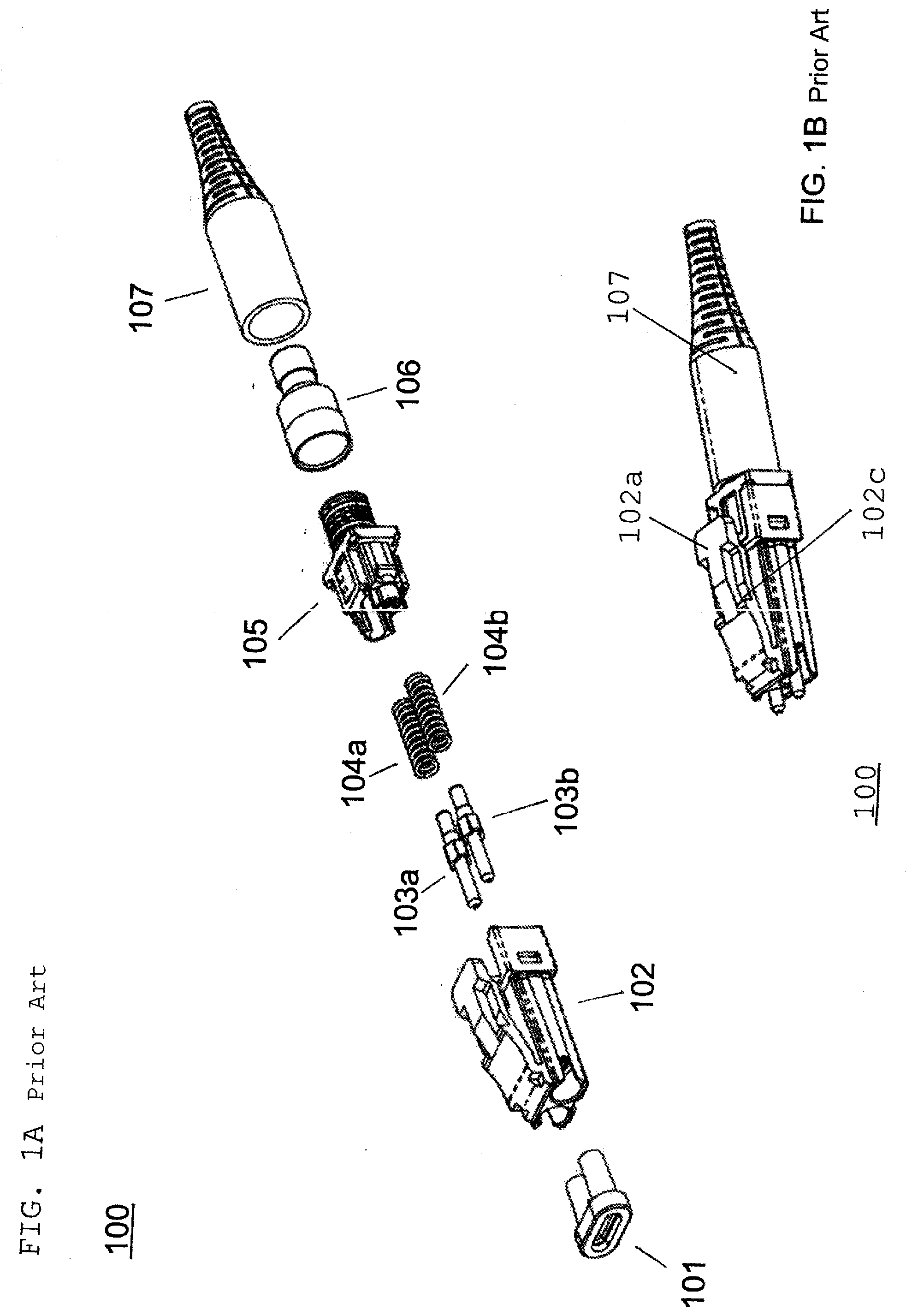
[0015] FIG. 1A is a perspective view of a prior art narrow pitch connector deploying a bend-latch release.
[0016] FIG. 1B is a perspective view of the bend latch connector of FIG. 1A assembled.
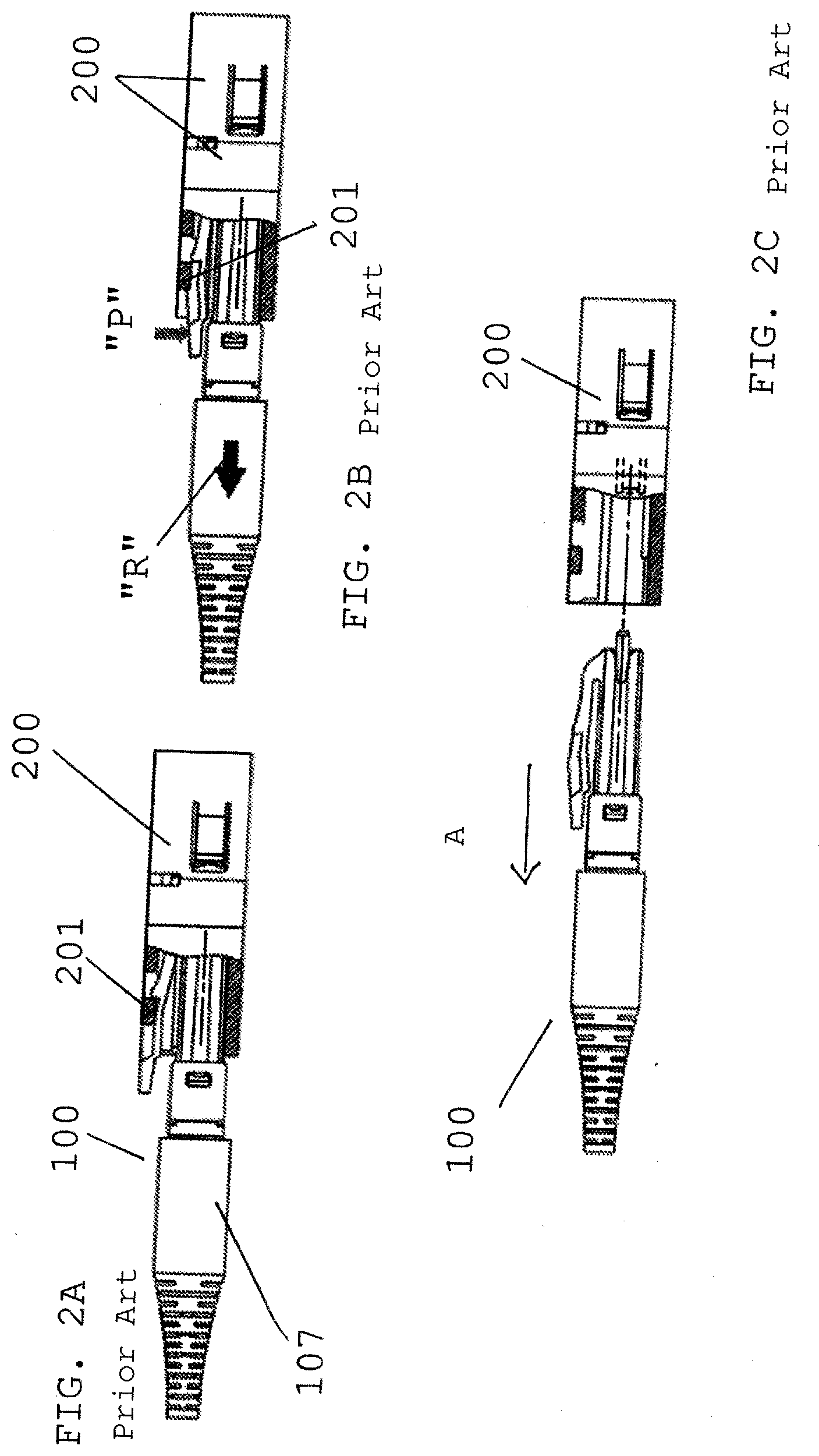
[0017] FIG. 2A is a perspective view of inserting the connector of FIG. 1A into a receptacle.
[0018] FIG. 2B is a perspective view of the connector of FIG. 1A at start of release from a receptacle.
[0019] FIG. 2C is a perspective view of the connector of FIG. 1A removed from a receptacle.
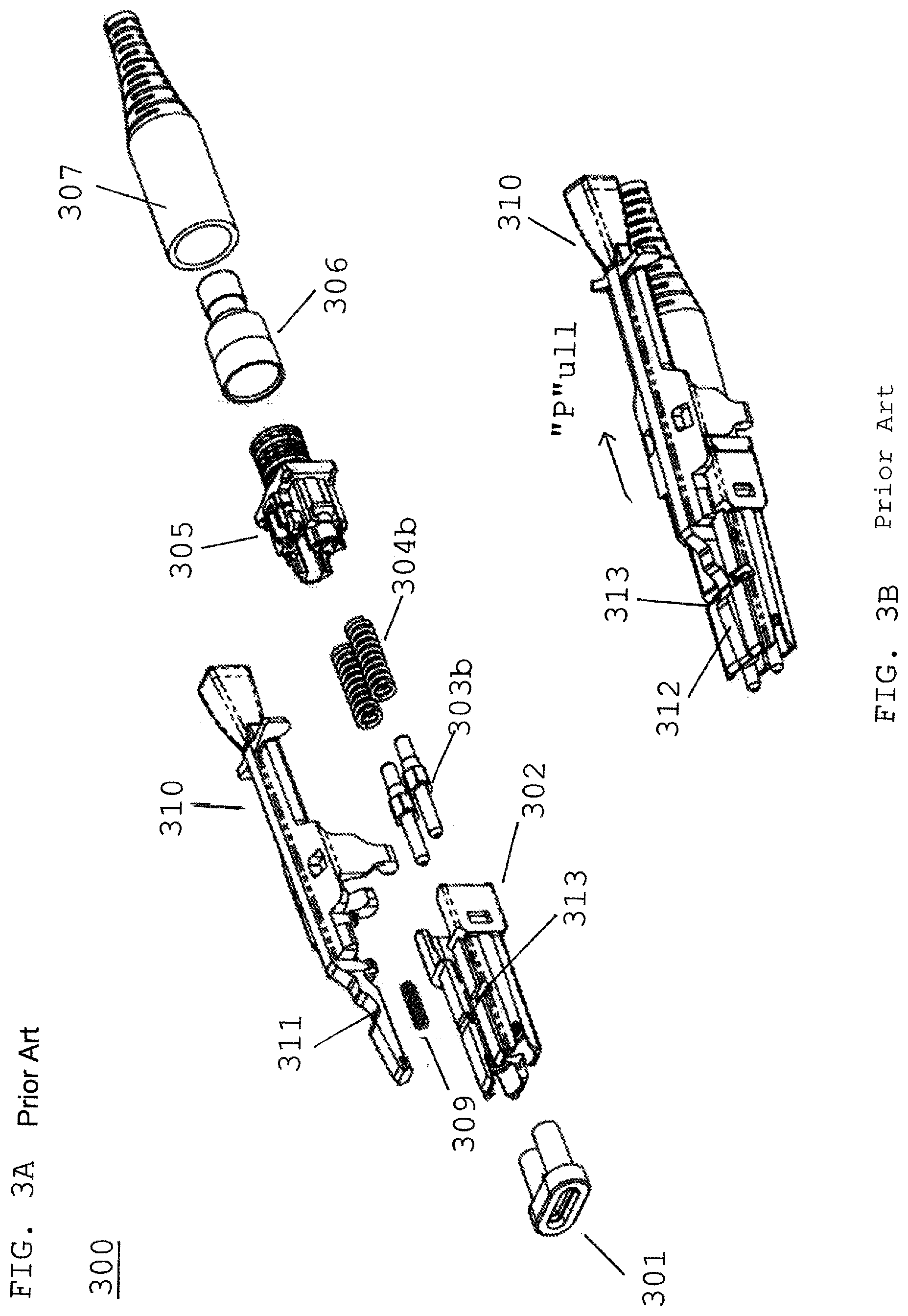
[0020] FIG. 3A is an exploded view of a prior art narrow pitch LC type connector.
[0021] FIG. 3B is an assembled view of FIG. 3A.
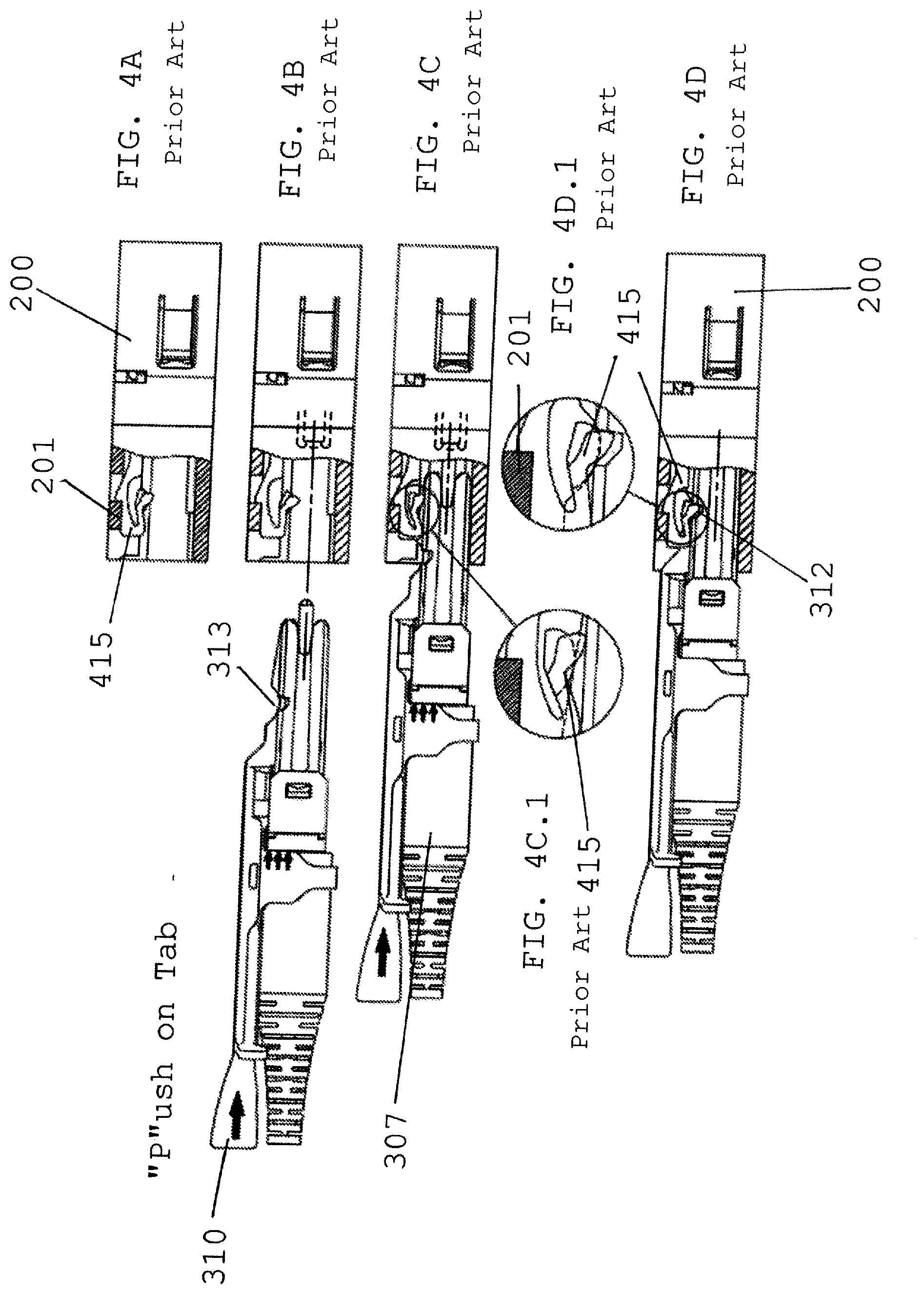
[0022] FIG. 4A is a perspective view of a receptacle with an anchor device within receptacle port.
[0023] FIG. 4B is a perspective view of FIG. 3B connector prior to insertion in receptacle of FIG. 4A.
[0024] FIG. 4C is a perspective view of FIG. 3B connector inserted into receptacle activating anchor device.
[0025] FIG. 4C.1 is a zoomed view of anchor device being lifted prior and secured in recess at front of connector of FIG. 3A.
[0026] FIG. 4D is a perspective view of FIG. 3B connector being removed from receptacle.
[0027] FIG. 4D.1 is a zoomed view of anchor device being lifted out of recess by pulling on push/pull tab.
[0028] FIG. 5 depicts an exploded view of a connector assembly according to a first embodiment.
[0029] FIG. 6 depicts is a perspective view of a proximal end of a connector assembly of FIG. 3B.
[0030] FIG. 6A depicts is a perspective view of the push-pull tab pulled rearward of the connector assembly of FIG. 3B.
[0031] FIG. 7 depicts a cross-section view of a receptacle having the connector of FIG. 6 therein.
[0032] FIG. 7A depicts a further cross-section taken of FIG. 6A while connector is being removed from receptacle.
[0033] FIG. 8 depicts a view of anchor device being moved up and out of recess during removal of connector of FIG. 3A from receptacle.
[0034] FIG. 8A depicts a side view of a connector assembly of FIG. 3A with anchor device fully removed from recess.
[0035] FIG. 9 is an exploded view of the present invention.
[0036] FIG. 10 is an assembled bottom view of the connector assembly of FIG. 9.
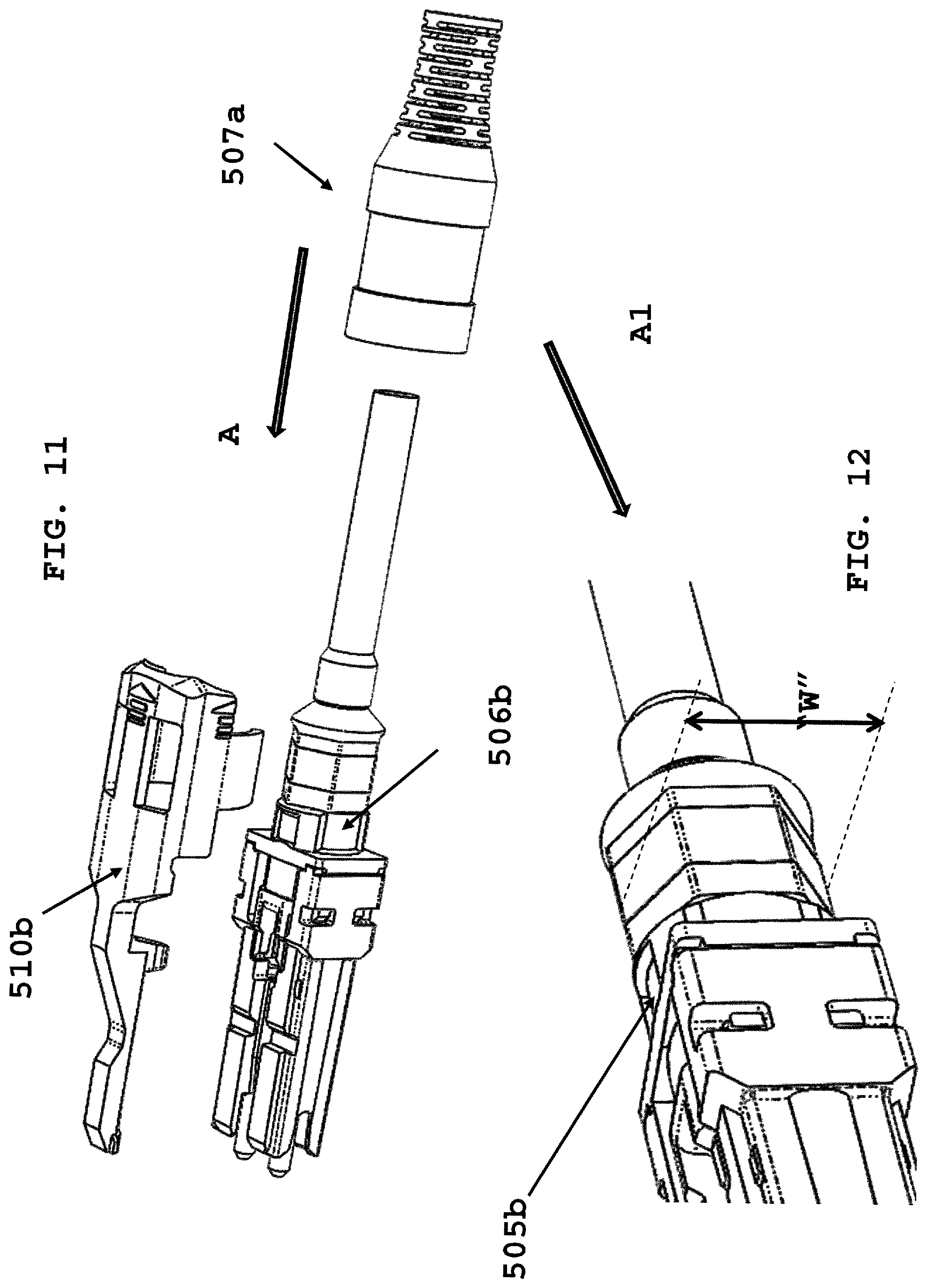
[0037] FIG. 11 is a partial exploded view of FIG. 9.
[0038] FIG. 12 is a side view of the connector crimp ring prior to securing cable boot.
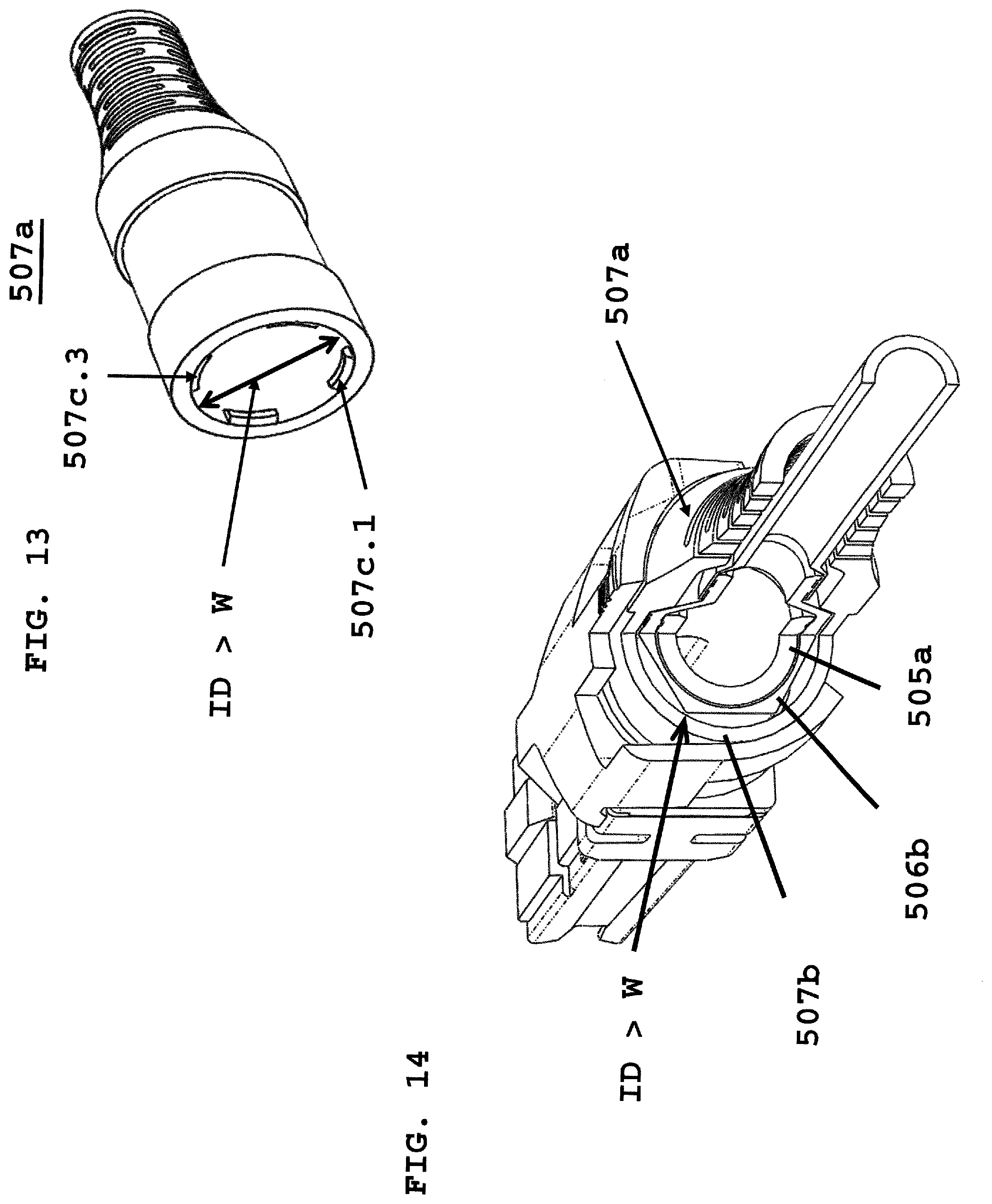
[0039] FIG. 13 is a front view of cable boot.
[0040] FIG. 14 is a cross-section of cable boot secured over rear of connector.
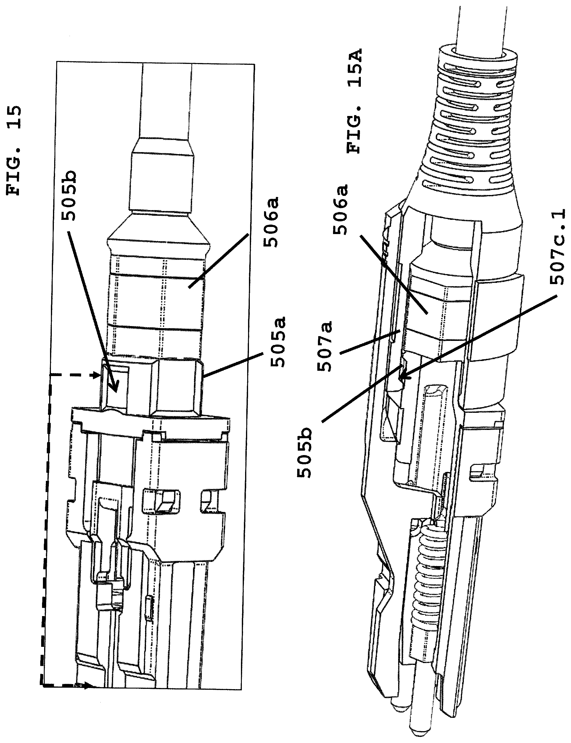
[0041] FIG. 15 is a perspective view of connector body without push/pull tab.
[0042] FIG. 15A is a partial cross-section of push/pull tab and cable boot secured to connector body.
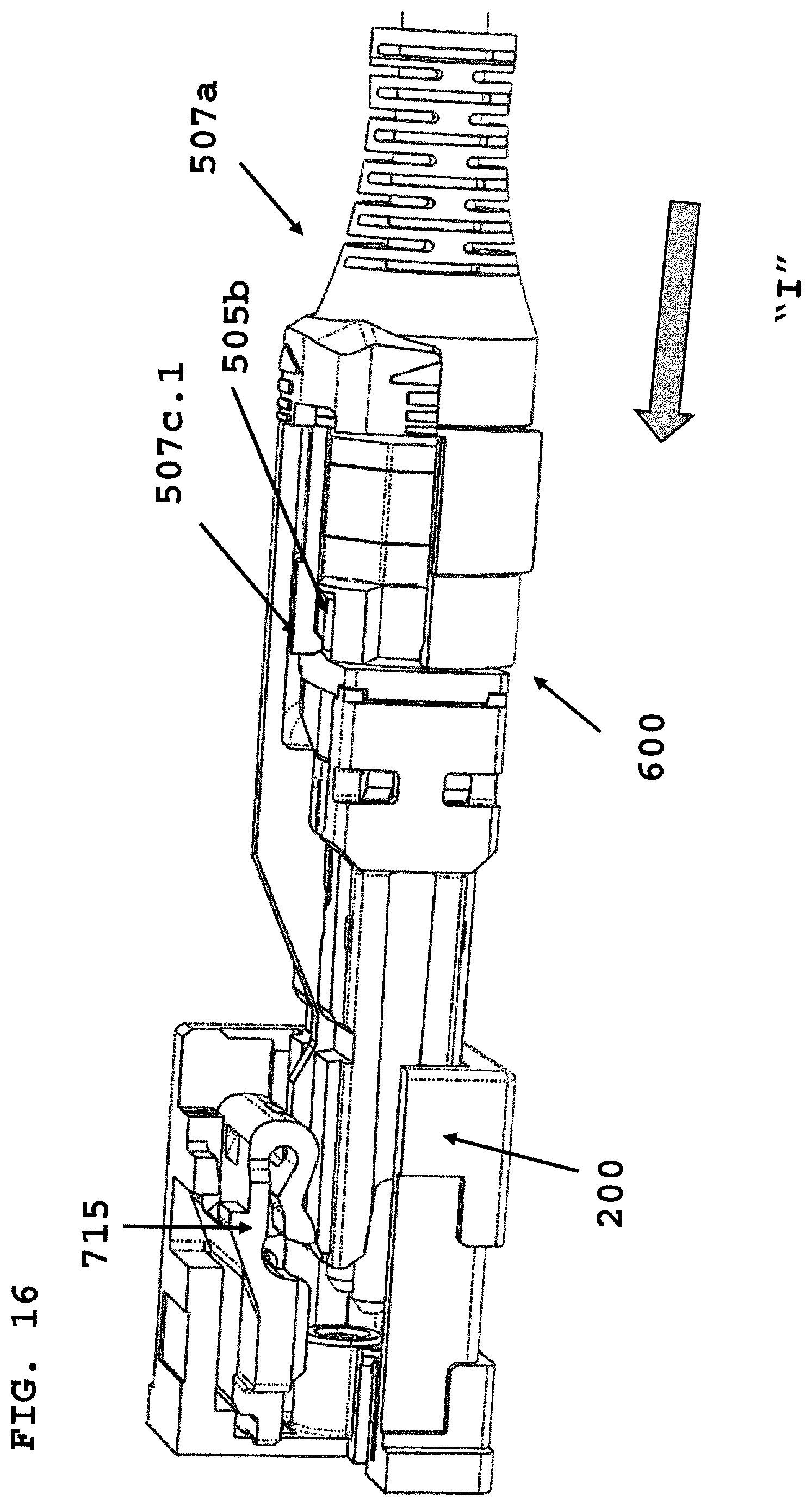
[0043] FIG. 16 depicts insertion of connector of FIG. 9 into a receptacle.
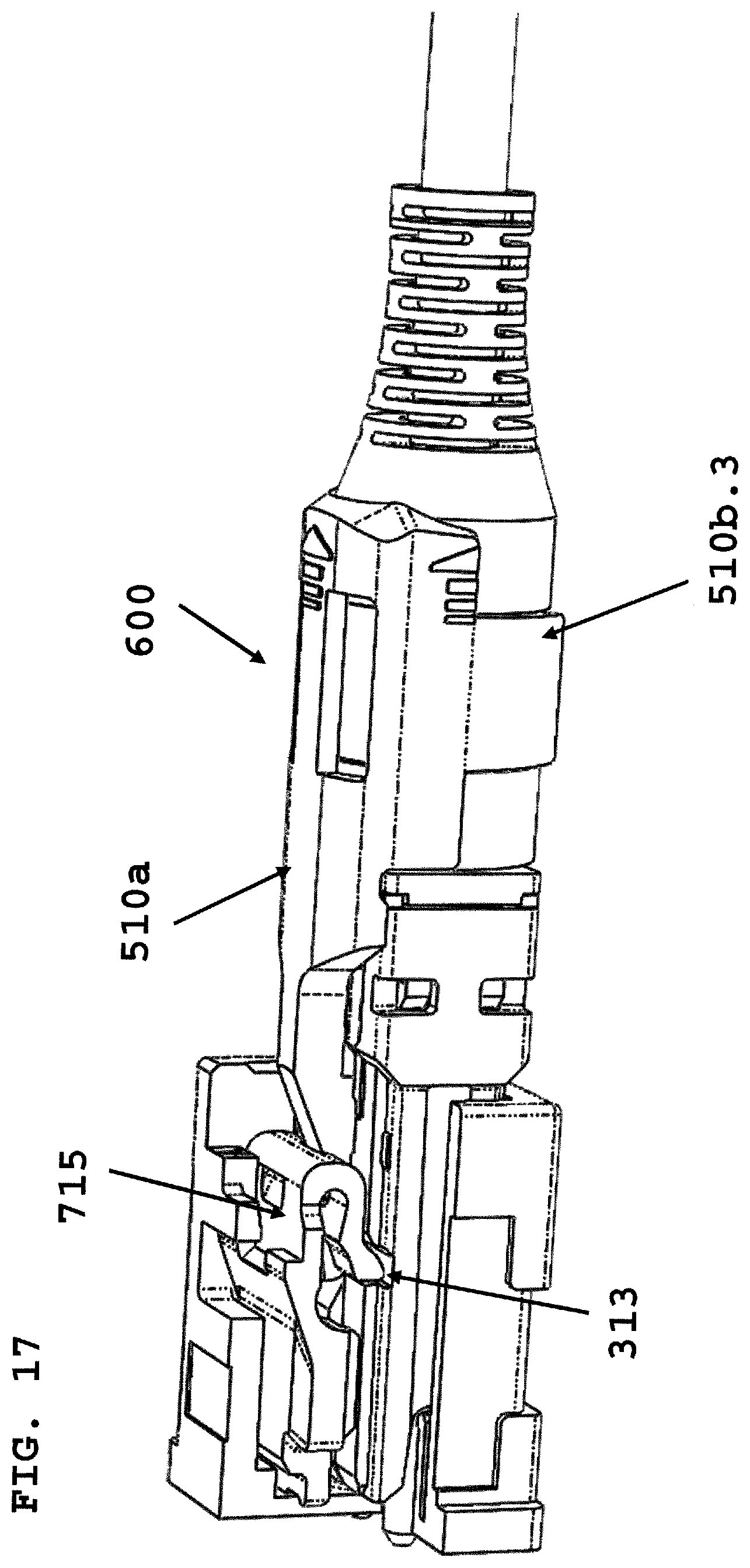
[0044] FIG. 17 depicts connector of FIG. 9 inserted into a receptacle.
[0045] FIG. 18 depicts removal of connector of FIG. 9 from a receptacle.
[0046] FIG. 19 depicts a raised surface to use to pull connector of FIG. 9 rearward.
DETAILED DESCRIPTION
[0047] This disclosure is not limited to the particular systems, devices and methods described, as these may vary. The terminology used in the description is for the purpose of describing the particular versions or embodiments only, and is not intended to limit the scope.
[0048] As used in this document, the singular forms "a," "an," and "the" include plural references unless the context clearly dictates otherwise. Unless defined otherwise, all technical and scientific terms used herein have the same meanings as commonly understood by one of ordinary skill in the art. Nothing in this disclosure is to be construed as an admission that the embodiments described in this disclosure are not entitled to antedate such disclosure by virtue of prior invention. As used in this document, the term "comprising" means "including, but not limited to."
[0049] The following terms shall have, for the purposes of this application, the respective meanings set forth below.
[0050] A connector, as used herein, refers to a device and/or component thereof that connects a first module or cable to a second module or cable. The connector may be configured for fiber optic transmission or electrical signal transmission. The connector may be any suitable type now known or later developed, such as, for example, a ferrule connector (FC), a fiber distributed data interface (FDDI) connector, an LC connector, a mechanical transfer (MT) connector, a square connector (SC) connector, an SC duplex connector, or a straight tip (ST) connector. The connector may generally be defined by a connector housing body. In some embodiments, the housing body may incorporate any or all of the components described herein.
[0051] A "fiber optic cable" or an "optical cable" refers to a cable containing one or more optical fibers for conducting optical signals in beams of light. The optical fibers can be constructed from any suitable transparent material, including glass, fiberglass, and plastic. The cable can include a jacket or sheathing material surrounding the optical fibers. In addition, the cable can be connected to a connector on one end or on both ends of the cable.
[0052] Various embodiments described herein generally provide a remote release mechanism such that a user can remove cable assembly connectors that are closely spaced together on a high-density panel without damaging surrounding connectors, accidentally disconnecting surrounding connectors, disrupting transmissions through surrounding connectors, and/or the like. Various embodiments also provide narrow pitch LC duplex connectors and narrow width multi-fiber connectors, for use, for example, with future narrow pitch LC SFPs and future narrow width SFPs. The remote release mechanisms allow use of the narrow pitch LC duplex connectors and narrow width multi-fiber connectors in dense arrays of narrow pitch LC SFPs and narrow width multi-fiber SFPs.
[0053] FIG. 1A depicts a prior art bend latch connector. The connector 100 comprises a dust cap 101, front body 102, ferrule assembly (103a, 103b), ferrule bias springs (104a, 104b), a back body 105, crimp ring 106 and cable boot 107. FIG. 1B is FIG. 1A assembled. Bend latch 102a is depressed to release latch surface 102c secured within a receptacle (not shown). FIG. 2A depicts connector 100 secured within receptacle 200, with latch surface 102c secured behind cut out 201. FIG. 2B depicts removing connector 100 by depressing at "P" latch 102. FIG. 2C depicts pulling connector 100 rearward, in direction of arrow A, until the connector is removed from receptacle 200. To remove this connector, a user must depress the latch very close to the receptacle port. When there are connectors side-by-side, the user may depress a second connector latch or could loosen the second connector in a second port. This would result in signal loss. FIG. 3A depicts an exploded view of a LC type prior art connector with a push/pull tab. The push/pull tab 310 is secured about front body. A bias spring 309 maintains tab 310 in a forward position, as shown in FIG. 6. Ferrule 303b is biased forward by spring 304b, and the spring/ferrule are held within front body 305. Crimp ring 306 is secured to back body, and cable boot 037 is secured to crimp ring 306. FIG. 3B depicts assembled connector 300. A width-wise recess 313 receives an anchor device 715 secured within a receptacle 200, refer to FIG. 7 below, to secure connector 300 within receptacle 200. A ramp surface 312 lifts anchor device upward as push/pull tab 310 is pulled in direction of "P". FIG. 4A depicts receptacle 200 with an anchor device 415 secured behind receptacle cut out 201. FIG. 4B shows connector 300 being inserted using push/pull tab 310 into receptacle 200. FIG. 4C shows connector 300 with anchor device entering in width-wise recess. FIG. 4C.1 is a zoomed view of anchor device 415 being secured within width-wise recess on connector front body, as connector 300 is inserted into receptacle 200. FIG. 4D depicts anchor device 415 being lifted by ramp surface 312 of push/pull tab 301. FIG. 4D.1 is a zoomed view of anchor device being lifted out of width-wise recess by ramp surface 312 as connector 300 is removed by pulling rearward on push/pull tab 310.
[0054] FIG. 5 depicts an exploded view of the present invention. Connector 500 comprises a front body 502 accepts ferrule 503b biased by spring 504b respectively, and held in place by back body 505a. Push/pull tab 510a attaches a proximal end of front body 502, is secured to back body 505a, and tab 510b.1 attaches about recess 507b of cable boot 507a. Cable boot 507a is secured about crimp ring 506a. Cable 506c jacket is secured and pressed with crimp ring 506a. Connector 500 is assembled from right to left. Ramp surface 504 lifts anchor device in recess 603 to release the connector from the receptacle port. FIG. 6A depicts a proximal end of connector 500 with push/pull tab 510a biased forward, and width-wise recess 603. FIG. 6B depicts connector 500 being pull rearward using push/pull tab 510a, where ramp surface 604 would lift an anchor device (not shown) within receptacle port.
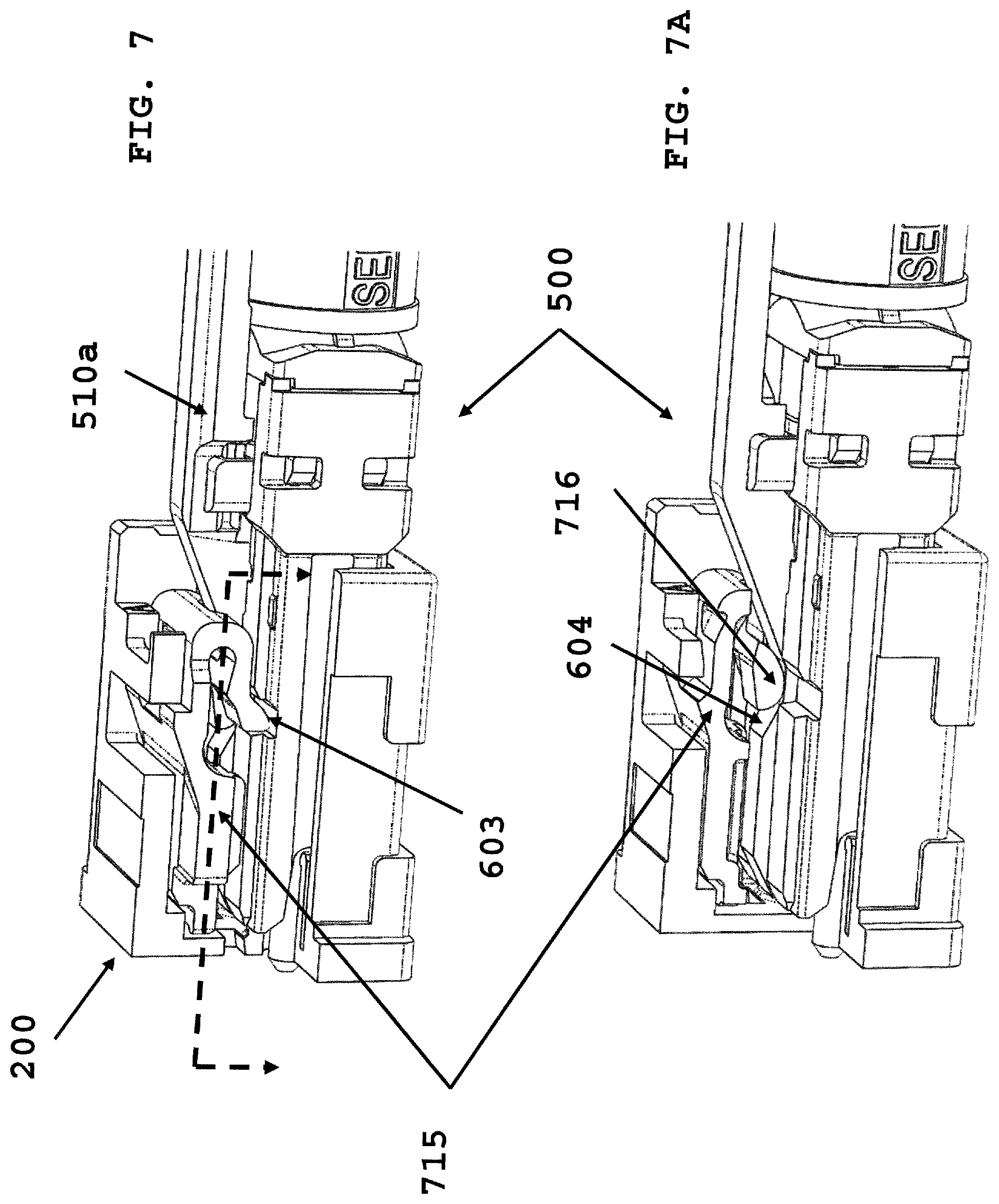
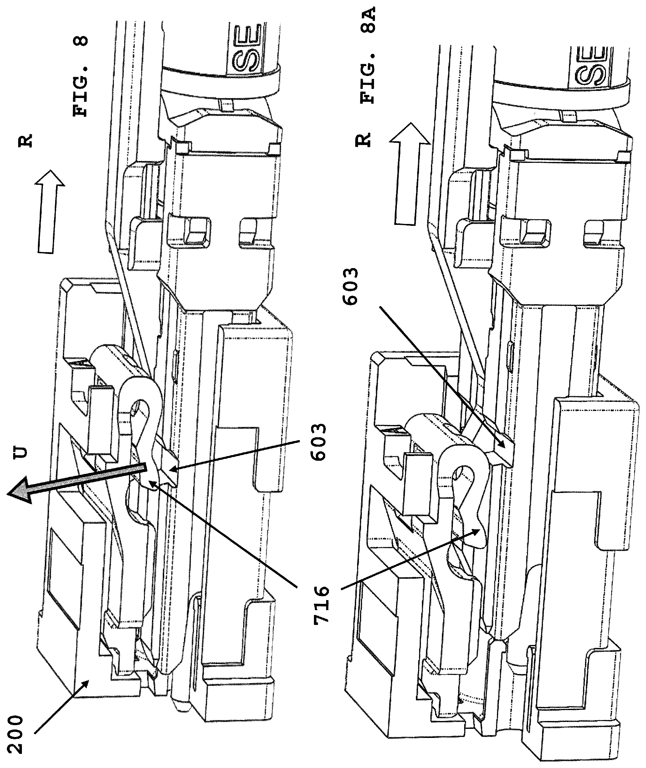
[0055] FIG. 7 depicts anchor device 715 retained within recess 603 that secures connector 500 in receptacle 200 port. FIG. 7A depicts a cross-section of FIG. 7 showing anchor device leg 716 within recess 603, and up against ramp surface 604, which is integrated with push/pull tab 510a. FIG. 8 depicts removing in direction of arrow R connector 500 from receptacle 200. Anchor leg 716 is lifted up (in direction of arrow U) by ramp surface 604. FIG. 8A depicts further rearward removal of the connector from the receptacle, where the anchor leg 716 is out of recess 603, and now released from the receptacle port.
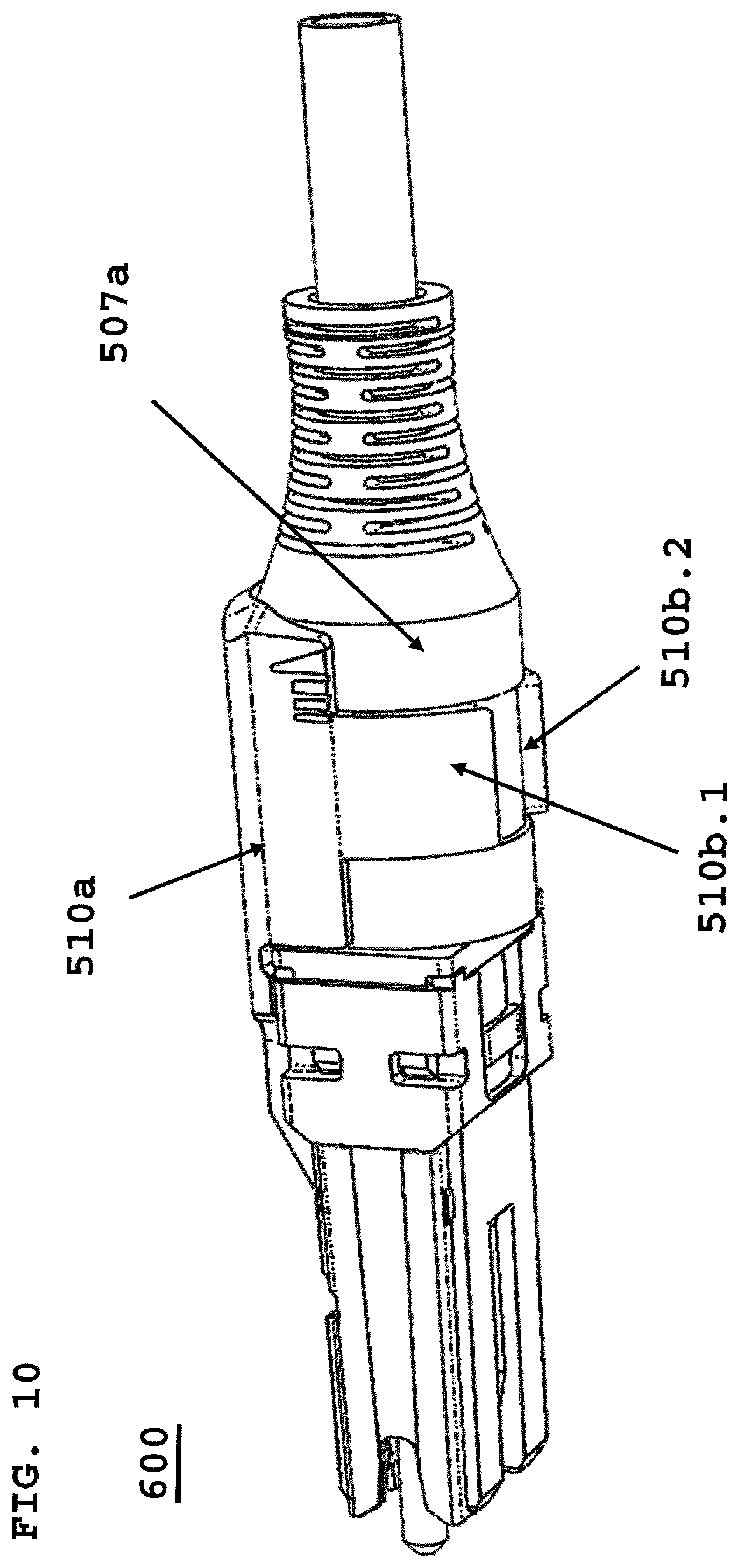
[0056] FIG. 9 is an exploded view of connector 500 prior to assembly of push/pull clip 510b, a second embodiment of the present invention. Proximal end 510d of clip 510b is secured to a proximal end 502b of front body, and wings 510b.1, 510b.2 are secured about circumferential recess 507b formed as part of the cable boot. Assembly is in direction of arrow "A" of push/pull clip 510b onto cable boot 507a. FIG. 10 depicts connector 600 with push/pull clip 510a assembled with wings (510b.1, 510b.2) secured about recess of cable boot 507a. FIG. 11 depicts an exploded view of securing cable boot 507a onto crimp sleeve 506b in direction of arrow "A". FIG. 12 depicts a zoomed view of crimp sleeve "W" width. Width "W" is the maximum outside dimension of crimp ring 506a over which cable boot 507a is placed. The inside dimension of cable boot 506a is sized to allow cable boot to be inserted over crimp ring sleeve 506b. This allows cable boot 507a to be secured onto back body 505a, using back body cut out 505b. Since back body 505a is secured to front body 502a, and push/pull clip 510a is secured about cable boot 506a, a rearward pulling on cable 506c or cable boot 507a will release connector (500, 600) from a receptacle port.
[0057] FIG. 13 depicts cable boot 507a. The inner diameter of cable boot at a proximal end opening, is slightly larger than the "W" of crimp ring sleeve 506b. Protrusions 507c.1 thru 507c.3, on an inside surface of cable boot. Cable boot 507a may have one or more protrusions that are secured within a corresponding cut out 505b on an outside surface of back body 505a. This secures and positions cable boot 507a over back body 505a. FIG. 14 is a cross-section cut-out of rear view of cable boot 507a secured over crimp ring sleeve 506b, and back body 505a is crimped over crimp ring. The cable boot is integrated with connector (550, 600), and by assembling the push/pull clip as shown in FIG. 10, a pull rearward on cable or cable boot will release connector from receptacle port.
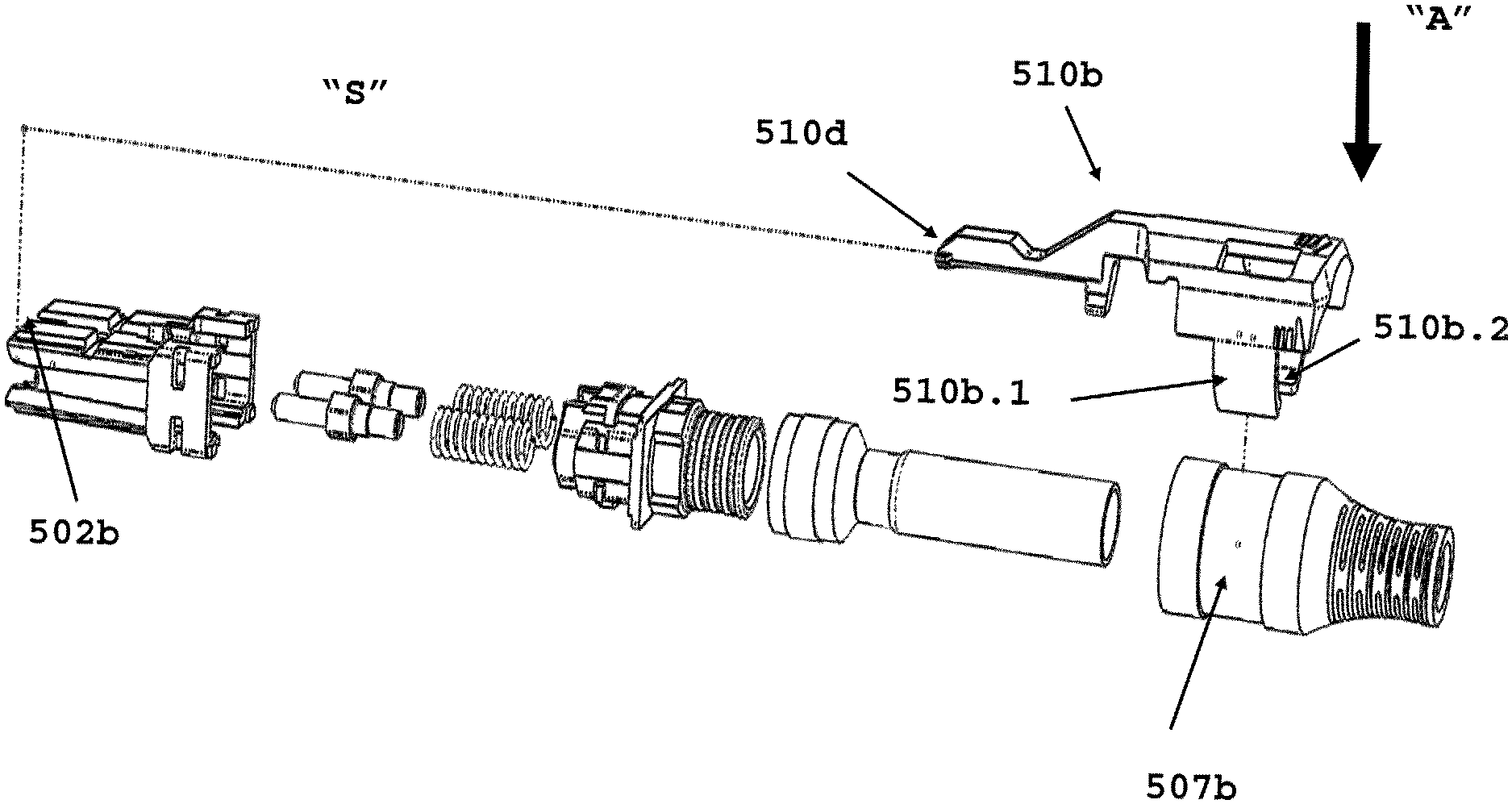
[0058] FIG. 15 depicts back body 505a cut out 505b, with back body secured within crimp ring 506a. FIG. 15A is a cross-section cut-out of FIG. 15 (shown by dotted line), with cable boot protrusion 507c.1 (although more than one protrusion/back body cut out can be used), moveable within back body cut out 505b. Upon pulling cable or cable boot rearward, protrusion 507c.1 moves rearward along cut out. The distance moved allows push/pull clip ramp surface 604 to lift anchor device leg 716 from widthwise recess 603, which releases connector 500 from a receptacle port. FIG. 16 depicts connector 600 being inserted into receptacle 200 port in direction of arrow "I". Anchor device 715 is out of recess. The cable boot protrusions 507c.1 is fully forward in back body recess/cut-out 505b. FIG. 17 depicts connector 600 fully inserted into receptacle port, with anchor leg 715 within width-wise recess 313. Wing 5120b.3 permanently may secures push/pull clip 510a to cable boot 507a.
[0059] FIG. 18 depicts connector (500, 600) being removed from receptacle port by a user pulling on cable boot 507a or cable 506c in direction of arrow "R". Protrusion 507c.1 moves rearward within back body cut-out/recess 505b, until protrusions is stopped by a recess stop face 505c. The length of recess 505b is sized to accommodate a protrusion 507c.1, and to allow ramp surface 604 to lift out anchor leg 517 from recess 503, and release connector (500, 600) from the receptacle port. FIG. 19 connector with a raised surface 600a or 600b to pull on to release connector.
[0060] In the above detailed description, reference is made to the accompanying drawings, which form a part hereof. In the drawings, similar symbols typically identify similar components, unless context dictates otherwise. The illustrative embodiments described in the detailed description, drawings, and claims are not meant to be limiting. Other embodiments may be used, and other changes may be made, without departing from the spirit or scope of the subject matter presented herein. It will be readily understood that the aspects of the present disclosure, as generally described herein, and illustrated in the Figures, can be arranged, substituted, combined, separated, and designed in a wide variety of different configurations, all of which are explicitly contemplated herein.
[0061] The present disclosure is not to be limited in terms of the particular embodiments described in this application, which are intended as illustrations of various aspects. Many modifications and variations can be made without departing from its spirit and scope, as will be apparent to those skilled in the art. Functionally equivalent methods and apparatuses within the scope of the disclosure, in addition to those enumerated herein, will be apparent to those skilled in the art from the foregoing descriptions. Such modifications and variations are intended to fall within the scope of the appended claims. The present disclosure is to be limited only by the terms of the appended claims, along with the full scope of equivalents to which such claims are entitled.
[0062] It will be understood by those within the art that, in general, terms used herein, and especially in the appended claims (for example, bodies of the appended claims) are generally intended as "open" terms (for example, the term "including" should be interpreted as "including but not limited to," the term "having" should be interpreted as "having at least," the term "includes" should be interpreted as "includes but is not limited to," et cetera). While various compositions, methods, and devices are described in terms of "comprising" various components or steps (interpreted as meaning "including, but not limited to"), the compositions, methods, and devices can also "consist essentially of" or "consist of" the various components and steps, and such terminology should be interpreted as defining essentially closed-member groups. It will be further understood by those within the art that if a specific number of an introduced claim recitation is intended, such an intent will be explicitly recited in the claim, and in the absence of such recitation no such intent is present. For example, as an aid to understanding, the following appended claims may contain usage of the introductory phrases "at least one" and "one or more" to introduce claim recitations. However, the use of such phrases should not be construed to imply that the introduction of a claim recitation by the indefinite articles "a" or "an" limits any particular claim containing such introduced claim recitation to embodiments containing only one such recitation, even when the same claim includes the introductory phrases "one or more" or "at least one" and indefinite articles such as "a" or "an" (for example, "a" and/or "an" should be interpreted to mean "at least one" or "one or more"); the same holds true for the use of definite articles used to introduce claim recitations. In addition, even if a specific number of an introduced claim recitation is explicitly recited, those skilled in the art will recognize that such recitation should be interpreted to mean at least the recited number (for example, the bare recitation of "two recitations," without other modifiers, means at least two recitations, or two or more recitations). Furthermore, in those instances where a convention analogous to "at least one of A, B, and C, et cetera" is used, in general such a construction is intended in the sense one having skill in the art would understand the convention (for example, "a system having at least one of A, B, and C" would include but not be limited to systems that have A alone, B alone, C alone, A and B together, A and C together, B and C together, and/or A, B, and C together, et cetera). In those instances where a convention analogous to "at least one of A, B, or C, et cetera" is used, in general such a construction is intended in the sense one having skill in the art would understand the convention (for example, "a system having at least one of A, B, or C" would include but not be limited to systems that have A alone, B alone, C alone, A and B together, A and C together, B and C together, and/or A, B, and C together, et cetera). It will be further understood by those within the art that virtually any disjunctive word and/or phrase presenting two or more alternative terms, whether in the description, claims, or drawings, should be understood to contemplate the possibilities of including one of the terms, either of the terms, or both terms. For example, the phrase "A or B" will be understood to include the possibilities of "A" or "B" or "A and B."
[0063] Various of the above-disclosed and other features and functions, or alternatives thereof, may be combined into many other different systems or applications. Various presently unforeseen or unanticipated alternatives, modifications, variations, or improvements therein may be subsequently made by those skilled in the art, each of which is also intended to be encompassed by the disclosed embodiments.
* * * * *
D00000
D00001
D00002
D00003
D00004
D00005
D00006
D00007
D00008
D00009
D00010
D00011
D00012
D00013
D00014
D00015
D00016

D00017

XML
uspto.report is an independent third-party trademark research tool that is not affiliated, endorsed, or sponsored by the United States Patent and Trademark Office (USPTO) or any other governmental organization. The information provided by uspto.report is based on publicly available data at the time of writing and is intended for informational purposes only.
While we strive to provide accurate and up-to-date information, we do not guarantee the accuracy, completeness, reliability, or suitability of the information displayed on this site. The use of this site is at your own risk. Any reliance you place on such information is therefore strictly at your own risk.
All official trademark data, including owner information, should be verified by visiting the official USPTO website at www.uspto.gov. This site is not intended to replace professional legal advice and should not be used as a substitute for consulting with a legal professional who is knowledgeable about trademark law.