Implementing Electronic Enclosure Cooling Containment For Concurrent Maintenance Actions
Anderl; William James ; et al.
U.S. patent application number 16/125590 was filed with the patent office on 2020-03-12 for implementing electronic enclosure cooling containment for concurrent maintenance actions. The applicant listed for this patent is International Business Machines Corporation. Invention is credited to William James Anderl, Phillip V. Mann.
| Application Number | 20200080570 16/125590 |
| Document ID | / |
| Family ID | 69718739 |
| Filed Date | 2020-03-12 |
| United States Patent Application | 20200080570 |
| Kind Code | A1 |
| Anderl; William James ; et al. | March 12, 2020 |
IMPLEMENTING ELECTRONIC ENCLOSURE COOLING CONTAINMENT FOR CONCURRENT MAINTENANCE ACTIONS
Abstract
Methods and structures are provided for implementing electronic enclosure cooling containment for concurrent maintenance actions with a top cover of the electronic enclosure removed. The structure includes a moveable airflow baffle being attached to the associated electronic enclosure. During concurrent maintenance actions, the moveable airflow baffle is moved to an open position over at least a partial length of a replaceable component, without being detached or removed from the associated electronic enclosure. During normal operations, the moveable airflow baffle hangs down over at least a partial length of a replaceable component.
| Inventors: | Anderl; William James; (Rochester, MN) ; Mann; Phillip V.; (Rochester, MN) | ||||||||||
| Applicant: |
|
||||||||||
|---|---|---|---|---|---|---|---|---|---|---|---|
| Family ID: | 69718739 | ||||||||||
| Appl. No.: | 16/125590 | ||||||||||
| Filed: | September 7, 2018 |
| Current U.S. Class: | 1/1 |
| Current CPC Class: | G06F 1/20 20130101; H05K 7/20009 20130101; G06F 1/181 20130101; F04D 29/563 20130101; H05K 7/2019 20130101; G06F 2200/201 20130101 |
| International Class: | F04D 29/56 20060101 F04D029/56; H05K 7/20 20060101 H05K007/20; G06F 1/20 20060101 G06F001/20; G06F 1/18 20060101 G06F001/18 |
Claims
1. A structure for implementing electronic enclosure cooling containment for concurrent maintenance actions with a top cover of the electronic enclosure removed comprising: a moveable airflow baffle being attached to an associated electronic enclosure; the moveable airflow baffle being moved to an open position over at least a partial length of a replaceable component for concurrent maintenance actions, without being detached or removed from the associated electronic enclosure; and during normal operations, the moveable airflow baffle hangs down over at least a partial length of a replaceable component.
2. The structure as recited in claim 1, wherein the moveable airflow baffle maintains typical airflow in the electronic enclosure for a period of time after the top cover is removed.
3. The structure as recited in claim 1, wherein the moveable airflow baffle being attached to an associated electronic enclosure includes the moveable airflow baffle attached to one of a chassis, a chassis bulkhead, and a system airflow baffle.
4. The structure as recited in claim 1, wherein the moveable airflow baffle includes a selected one of a hinged attachment and a fixed attachment to the associated electronic enclosure.
5. The structure as recited in claim 1, includes a free end of the moveable airflow baffle free floating during normal operations.
6. The structure as recited in claim 1, includes a free end of the moveable airflow baffle held open when moved to the open position, and the free end of the moveable airflow baffle returning to its position for normal operations when the moveable airflow baffle is not held open.
7. The structure as recited in claim 1, wherein the moveable airflow baffle prevents a cover of the associated electronic enclosure from being installed in the open position.
8. The structure as recited in claim 1, wherein the moveable airflow baffle includes a selected one of a plastic moveable airflow baffle, and rubber moveable airflow baffle.
9. The structure as recited in claim 1, wherein the moveable airflow baffle is formed of a flexible material having sufficient rigidity and strength to prevent a cover of the associated electronic enclosure from being installed when the moveable airflow baffle is in the open position.
10. The structure as recited in claim 1, wherein the moveable airflow baffle includes a finger loop at a free end used to assist moving the moveable airflow baffle.
11. A method for implementing electronic enclosure cooling containment for concurrent maintenance actions with a top cover of the electronic enclosure removed comprising: providing a moveable airflow baffle being attached to an associated electronic enclosure; moving the moveable airflow baffle to an open position over at least a partial length of a replaceable component for concurrent maintenance actions, without being detached or removed from the associated electronic enclosure; and during normal operations, providing the moveable airflow baffle to hang down over at least a partial length of a replaceable component.
12. The method as recited in claim 11, includes providing a finger loop at a free end used to move the moveable airflow baffle.
13. The method as recited in claim 11, wherein providing the moveable airflow baffle includes providing a selected one of a hinged attachment and a fixed attachment to the associated electronic enclosure.
14. The method as recited in claim 11, wherein providing the moveable airflow baffle includes preventing a cover of the associated electronic from being installed with the moveable airflow baffle in the open position.
15. The method as recited in claim 11, wherein providing the moveable airflow baffle includes providing a selected one of a plastic moveable airflow baffle, and rubber moveable airflow baffle.
16. The method as recited in claim 11, wherein providing the moveable airflow baffle includes forming the moveable airflow baffle of a flexible material having sufficient rigidity and strength to prevent a cover of the associated electronic enclosure from being installed when the moveable airflow baffle is in the open position.
17. The method as recited in claim 11, wherein providing the moveable airflow baffle includes providing the moveable airflow baffle to maintain typical airflow in the electronic enclosure for a period of time after the top cover is removed.
18. The method as recited in claim 11, wherein providing the moveable airflow baffle includes a free end of the moveable airflow baffle free floating during normal operations.
19. The method as recited in claim 11, wherein providing the moveable airflow baffle includes providing a free end of the moveable airflow baffle held open when moved to the open position.
20. The method as recited in claim 11, wherein providing the moveable airflow baffle includes providing a free end of the moveable airflow baffle returning to its position for normal operations when the moveable airflow baffle is not held open.
Description
FIELD OF THE INVENTION
[0001] The present disclosure relates generally to the data processing field, and more particularly, relates to methods and structures for implementing electronic enclosure cooling containment for concurrent maintenance actions.
BACKGROUND
[0002] Cooling can no longer be indefinitely provided for high powered Peripheral Component Interconnect Express (PCI-Express or PCIe) adapters during customer concurrence maintenance actions. During customer concurrence maintenance action the top cover of the system is removed for an undetermined long time.
[0003] Majority of industry do not allow concurrence maintenance in PCIe adapters. System maintenance generally requires a system shut down, and concurrently maintainable systems may require time limits, such as less than 5 minutes. Also additional baffling is incorporated into the existing system.
SUMMARY
[0004] Principal aspects of the present disclosure are to provide methods and structures for implementing electronic enclosure cooling containment for concurrent maintenance actions with a top cover of the electronic enclosure removed. Other important aspects of the present disclosure are to provide such methods and structures substantially without negative effects and that overcome many of the disadvantages of prior art arrangements.
[0005] In brief, methods and structures are provided for implementing electronic enclosure cooling containment for concurrent maintenance actions with a top cover of the electronic enclosure removed. The structure includes a moveable airflow baffle being attached to the associated electronic enclosure. During concurrent maintenance actions, the moveable airflow baffle is moved to an open position over at least a partial length of a replaceable component, without being detached or removed from the associated electronic enclosure. During normal operations, the moveable airflow baffle hangs down over at least a partial length of a replaceable component.
[0006] In accordance with features of the disclosure, the moveable airflow baffle can be affixed or attached to a chassis, a chassis bulkhead, or an existing airflow baffle within the electronic enclosure. The moveable airflow baffle optionally includes a finger loop at a free end used to assist with opening and holding open the moveable airflow baffle.
[0007] In accordance with an embodiment of the disclosure, during normal operations, the moveable airflow baffle hangs down over at least a partial length of a PCIe or other replaceable components, such as memory.
[0008] In accordance with an embodiment of the disclosure, the moveable airflow baffle replaces a system baffle.
[0009] In accordance with features of the disclosure, the free end of the moveable airflow baffle optionally is free floating during normal operations. The free end of the moveable airflow baffle optionally includes a latch or magnet catch operable during normal operations.
[0010] In accordance with features of the disclosure, optionally the free end of the moveable airflow baffle is held open when moved to the open position. In the open position, the moveable airflow baffle prevents a cover, or a separate portion of the cover, of the associated electronic enclosure from being installed. The cover of the associated electronic enclosure is installed with the free end of the moveable airflow baffle moved or allowed to return to its position over the at least partial length of the replaceable component for normal operations.
[0011] In accordance with features of the disclosure, the moveable airflow baffle is formed of a selected material, such as plastic, rubber, or other flexible material, having sufficient rigidity and strength to prevent a cover of the associated electronic enclosure from being installed when the moveable airflow baffle is in the open position. The selected material has sufficient elasticity to allow it to bend to its open position and optionally return on its own or spring back to its position for normal operation if not manually held in its open position.
BRIEF DESCRIPTION OF THE DRAWINGS
[0012] The present disclosure together with the above and other objects and advantages may best be understood from the following detailed description of the preferred embodiments of the disclosure illustrated in the drawings, wherein:
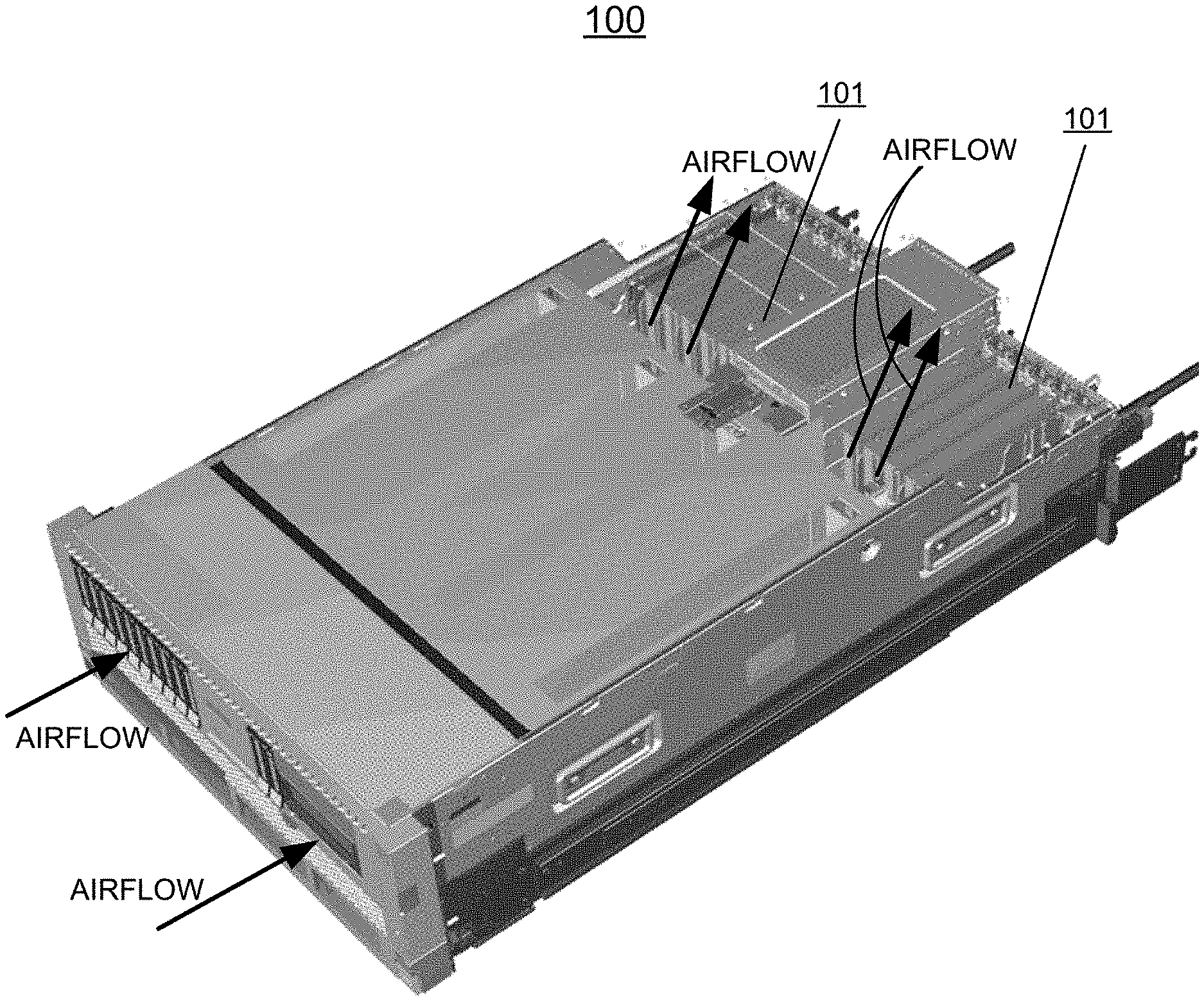
[0013] FIG. 1 is a perspective view not to scale schematically illustrating an example enclosure for implementing electronic enclosure cooling containment for concurrent maintenance actions with a top cover of the electronic enclosure removed in accordance with an illustrative embodiment;
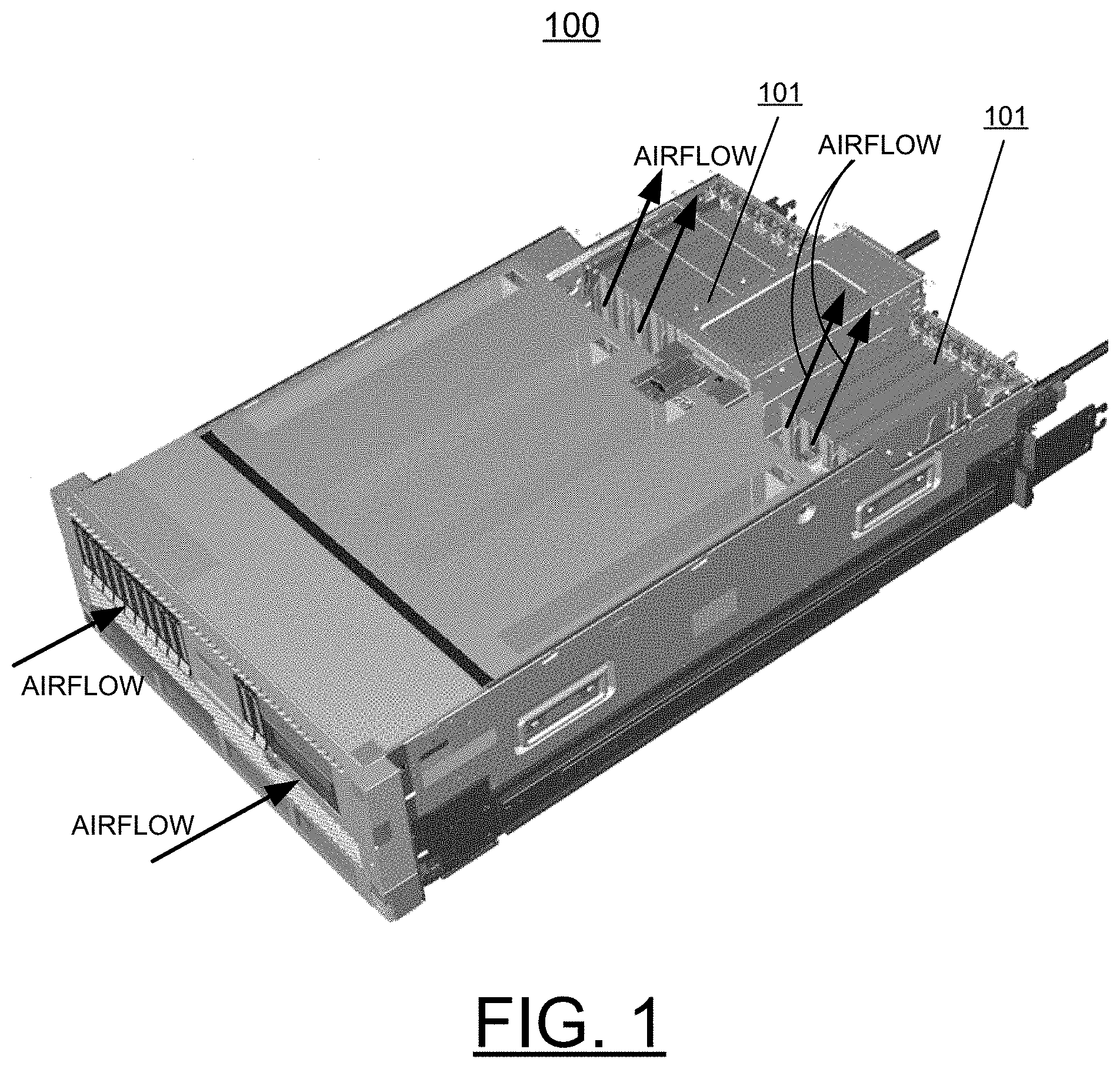
[0014] FIG. 2 is a perspective view not to scale schematically illustrating an example structure for implementing electronic enclosure cooling containment for concurrent maintenance actions with a top cover of the electronic enclosure removed in accordance with an illustrative embodiment;
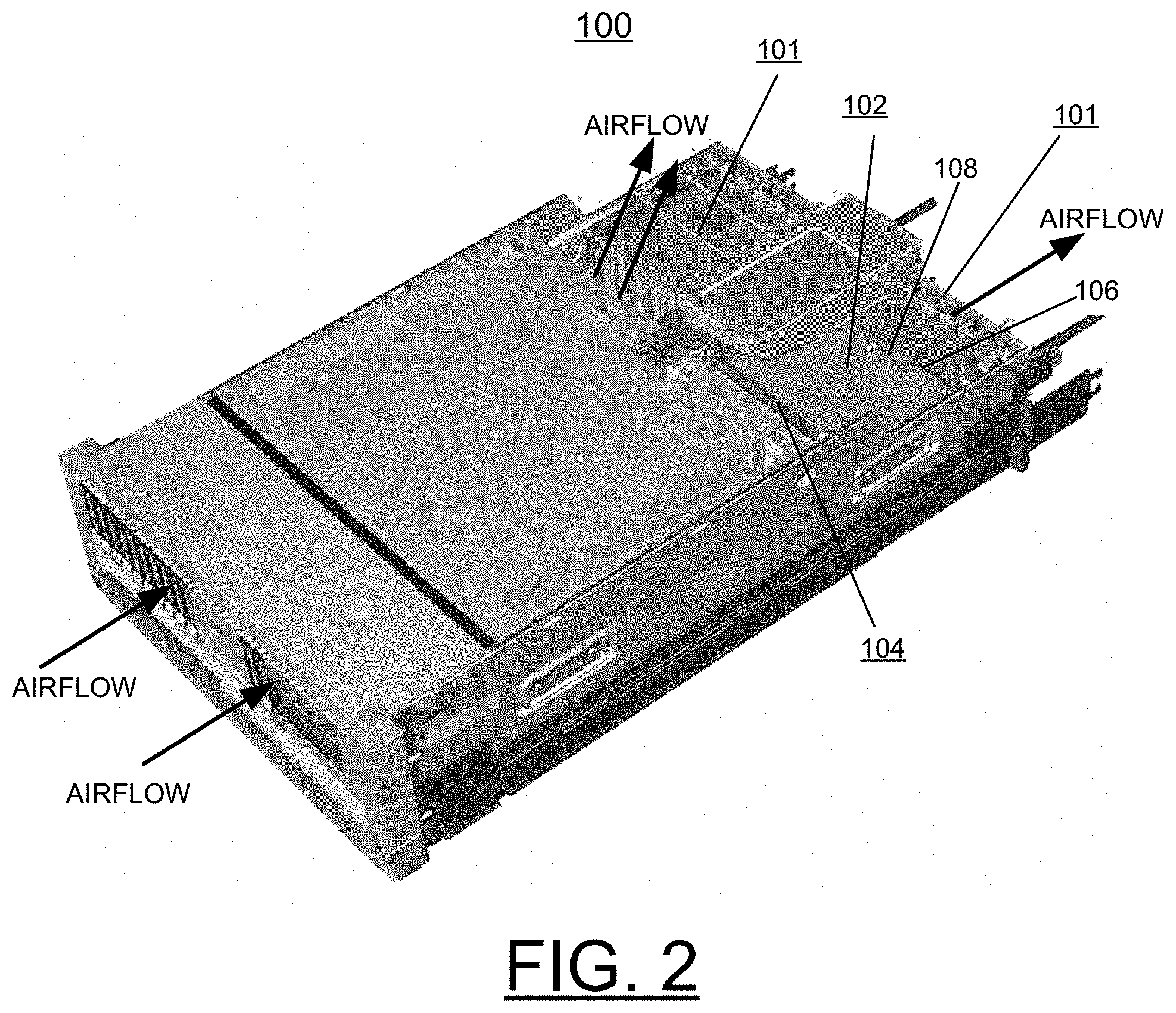
[0015] FIG. 3 is a side view not to scale schematically illustrating example features of the example moveable airflow baffle in a normal position in accordance with an illustrative embodiment; and
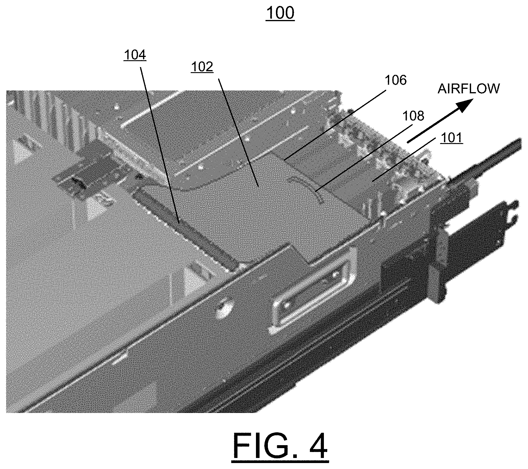
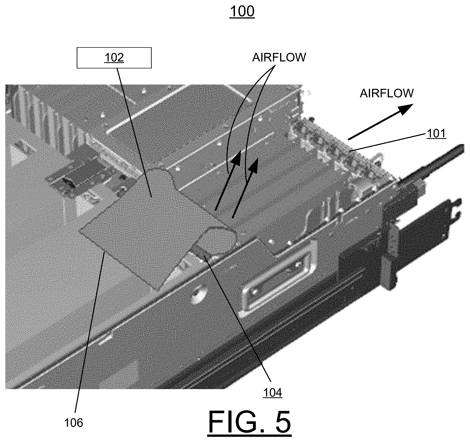
[0016] FIGS. 4, and 5 are respective detailed views illustrating the moveable airflow baffle in a normal position in FIG. 4 and in an open position in FIG. 5 for concurrent maintenance actions in accordance with an illustrative embodiment.
DETAILED DESCRIPTION OF THE PREFERRED EMBODIMENTS
[0017] In the following detailed description of embodiments of the disclosure, reference is made to the accompanying drawings, which illustrate example embodiments by which the disclosure may be practiced. It is to be understood that other embodiments may be utilized and structural changes may be made without departing from the scope of the disclosure.
[0018] The terminology used herein is for the purpose of describing particular embodiments only and is not intended to be limiting of the disclosure. As used herein, the singular forms "a", "an" and "the" are intended to include the plural forms as well, unless the context clearly indicates otherwise. It will be further understood that the terms "comprises" and/or "comprising," when used in this specification, specify the presence of stated features, integers, steps, operations, elements, and/or components, but do not preclude the presence or addition of one or more other features, integers, steps, operations, elements, components, and/or groups thereof.
[0019] In accordance with features of the disclosure, methods and structures are provided for implementing electronic enclosure cooling containment for concurrent maintenance actions with a top cover of the electronic enclosure removed. The structure includes a moveable airflow baffle being attached to the associated electronic enclosure. During concurrent maintenance actions, the moveable airflow baffle is moved to an open position over at least a partial length of a replaceable component, without being detached or removed from the associated electronic enclosure. In the open position, the moveable airflow baffle prevents the top cover of the associated electronic enclosure from being installed. The moveable airflow baffle is formed of a selected flexible material, having sufficient rigidity and strength to prevent the cover of the associated electronic enclosure from being installed when the moveable airflow baffle is in the open position. The selected material has sufficient elasticity to allow it to bend to its open position and optionally return on its own or spring back to its position for normal operation if not manually held in its open position.
[0020] In accordance with features of the disclosure, the moveable airflow baffle optionally replaces a system baffle.
[0021] Referring now to FIG. 1, there is shown a perspective view not to scale schematically illustrating an example enclosure generally designated by the reference character 100 for implementing electronic enclosure cooling containment for concurrent maintenance actions with a top cover of the electronic enclosure removed in accordance with an illustrative embodiment. As shown, enclosure 100 includes tandem areas 101 of the example system enclosure 100 arranged for concurrent maintenance actions. As shown, airflow enters at a front of the associated electronic enclosure 100 as indicated by arrows labeled AIRFLOW and exits at a front portion of the tandem areas 101 without reaching a rear or back of the associated electronic enclosure 100.
[0022] Referring also to FIGS. 2-5, system enclosure 100 optionally includes high powered PCI-Express (PCIe) adapters including one or more moveable airflow baffles 102 provided in one or more areas 101, such as hanging over at least a partial length of PCI, PCI dividers or other replaceable components such as memory. As shown, airflow enters at the front of the associated electronic enclosure 100 indicated by arrows labeled AIRFLOW and exits at the rear or back of the associated electronic enclosure 100 with the moveable airflow baffle 102 in the area 101. In FIG. 2, in the area 101 not including a moveable airflow baffle 102, the airflow exits at a front portion of the tandem areas 101 without reaching a rear or back of the associated electronic enclosure 100.
[0023] In accordance with features of the disclosure, the moveable airflow baffle 102 provides electronic enclosure cooling containment to keep airflow in the system 100 longer when the top cover is removed. The moveable airflow baffle optionally replaces a system baffle of the associated electronic enclosure 100. During normal operations, the moveable airflow baffle 102 hangs down over at least a partial length of a replaceable component.
[0024] Referring now to FIGS. 2 and 3, there is shown an example structure comprising a moveable airflow baffle generally designated by the reference character 102 for implementing electronic enclosure cooling containment for concurrent maintenance actions in accordance with an illustrative embodiment. The moveable airflow baffle 102 is attached to the associated electronic enclosure 100. The moveable airflow baffle 102 is hinged or fixedly attached at a fixed end 104 to one of a chassis, a chassis bulkhead, and a system airflow baffle of the associated electronic enclosure. The moveable airflow baffle 102 is arranged as a permanent feature that is not removed.
[0025] In FIGS. 2 and 3, example features of the moveable airflow baffle 102 include that in a normal position in accordance with an illustrative embodiment a free end 106 of the moveable airflow baffle 102 is free floating, hanging down over at least a partial length of a replaceable component in area 101. Optionally the free end 106 of the moveable airflow baffle includes a latch or magnet catch. Airflow enters the front end of the associated electronic enclosure 100 as indicated by arrows labeled AIRFLOW toward and proximate to the free end 106 of the moveable airflow baffle 102. During normal operation, the free end 106 of the moveable airflow baffle 102 rests between the top of the replaceable components and the enclosure's top cover, without obstructing airflow or mechanical movement of the top cover. During concurrent maintenance, with the cover off, the free end 106 of the moveable airflow baffle 102 will not blow open.
[0026] In accordance with features of the disclosure, the moveable airflow baffle 102 is formed of a selected material, such as plastic, rubber, or other flexible material. The moveable airflow baffle 102 has sufficient rigidity and strength to prevent a cover of the associated electronic enclosure 100 from being installed when the moveable airflow baffle is in the open position. The free end 106 of the moveable airflow baffle 102 is angled downwardly, hangs down over a partial length of the PCI, or other replaceable component and can be in contact with the a lid or rest on the top of a PCI or PCI dividers, or special guide ledges.
[0027] FIGS. 4, and 5 are respective detailed views illustrating the moveable airflow baffle 102 in a normal position in FIG. 4, and move to an open position in FIG. 5 for concurrent maintenance actions in accordance with an illustrative embodiment.
[0028] As illustrated in FIG. 4, during normal operation, the moveable airflow baffle 102 is attached at fixed end 104 extending over at least a partial length of a replaceable component and the free end 106 and is free floating at the free end 106. Airflow is indicated by arrow labeled AIRFLOW toward and proximate to the free end 106 of the moveable airflow baffle 102. During normal operation, the free end 106 of the moveable airflow baffle 102 remains hanging downward on the replaceable component, and does not blow open.
[0029] In accordance with features of the disclosure, the moveable airflow baffle 102 optionally includes a finger loop 108 near a free end 106 that is used to assist moving the moveable airflow baffle.
[0030] It should be understood that the moveable airflow baffle 102 is not limited to features of the illustrated disclosure. For example, a latch or some retention feature could be incorporated near the free floating end 106 of the moveable airflow baffle 102.
[0031] As illustrated in FIG. 5, during concurrent maintenance actions, the moveable airflow baffle 102 is moved to an open position over at least a partial length of a replaceable component 101, without being detached or moved from the associated electronic enclosure 100. Optionally the free end 106 of the moveable airflow baffle 102 is held open when moved to the open position. In the open position, some airflow exits the intended region when the airflow baffle 102 is held in the maintenance position. When the airflow baffle 102 is let go, it returns to the operational position and typical airflow resumes, as shown in FIG. 4. In the open position, the moveable airflow baffle 102 prevents a cover of the associated electronic enclosure from being installed. The cover of the associated electronic enclosure 100 is installed with the free end 106 of the moveable airflow baffle 102 moved back or allowed to return to its position over the partial length of the replaceable component for normal operations.
[0032] In accordance with features of the disclosure, the moveable airflow baffle 102 is formed of a selected material, such as plastic, rubber, or other flexible material having sufficient rigidity and strength to prevent a cover of the associated electronic enclosure from being installed when the moveable airflow baffle is in the open position. The selected material has sufficient elasticity to allow it to bend to its open position and optionally return on its own or spring back to its position for normal operation if not manually held in its open position.
[0033] While the present disclosure has been described with reference to the details of the embodiments of the disclosure shown in the drawing, these details are not intended to limit the scope of the disclosure as claimed in the appended claims.
* * * * *
D00000
D00001
D00002
D00003
D00004
D00005
XML
uspto.report is an independent third-party trademark research tool that is not affiliated, endorsed, or sponsored by the United States Patent and Trademark Office (USPTO) or any other governmental organization. The information provided by uspto.report is based on publicly available data at the time of writing and is intended for informational purposes only.
While we strive to provide accurate and up-to-date information, we do not guarantee the accuracy, completeness, reliability, or suitability of the information displayed on this site. The use of this site is at your own risk. Any reliance you place on such information is therefore strictly at your own risk.
All official trademark data, including owner information, should be verified by visiting the official USPTO website at www.uspto.gov. This site is not intended to replace professional legal advice and should not be used as a substitute for consulting with a legal professional who is knowledgeable about trademark law.