Fa Ade Structure
Girnghuber; Claus ; et al.
U.S. patent application number 16/567698 was filed with the patent office on 2020-03-12 for fa ade structure. The applicant listed for this patent is Moeding Keramikfassaden GmbH. Invention is credited to Claus Girnghuber, Dietmar Muller, Rudolf Wagner.
| Application Number | 20200080317 16/567698 |
| Document ID | / |
| Family ID | 63579082 |
| Filed Date | 2020-03-12 |

| United States Patent Application | 20200080317 |
| Kind Code | A1 |
| Girnghuber; Claus ; et al. | March 12, 2020 |
FA ADE STRUCTURE
Abstract
A facade structure is described, preferably a curtain-wall back-ventilated facade structure, with a substructure formed from support profiles which is arranged in front of a building wall and anchored fixedly in the floor and/or in the building wall, with extruded facade tiles made of ceramic material, preferably clay material, which are fastened to the substructure via tile holders. In order to be able to arrange the facade tiles in the vertical format, in addition to the tile holders which grip on the vertical edges of the facade tiles, it is provided that weight-supporting holders, which have receivers which engage in each case in a lower edge of the facade tiles, are fastened to the support profiles to which the tile holders are fastened or to further support profiles of the substructure directly or via separate supports.
| Inventors: | Girnghuber; Claus; (Marklkofen, DE) ; Wagner; Rudolf; (Straubing, DE) ; Muller; Dietmar; (Frontenhausen, DE) | ||||||||||
| Applicant: |
|
||||||||||
|---|---|---|---|---|---|---|---|---|---|---|---|
| Family ID: | 63579082 | ||||||||||
| Appl. No.: | 16/567698 | ||||||||||
| Filed: | September 11, 2019 |
| Current U.S. Class: | 1/1 |
| Current CPC Class: | E04F 13/0819 20130101; E04F 2203/04 20130101; E04F 13/0812 20130101; E04F 13/142 20130101; E04F 13/083 20130101; E04F 13/0826 20130101 |
| International Class: | E04F 13/08 20060101 E04F013/08 |
Foreign Application Data
| Date | Code | Application Number |
|---|---|---|
| Sep 12, 2018 | EP | 18194066.9 |
Claims
1. A facade structure, with a substructure formed of support profiles, which is arranged in front of a building wall and anchored fixedly in the floor and/or in the building wall, with facade tiles formed with ridges and/or extruded, which are fastened to the substructure via tile holders, wherein all or only some of the support profiles have the tile holders, wherein the tile holders are fastened to the support profiles directly or via separate supports, and the tile holders have receivers, which engage with edge areas of the facade tiles to fasten the facade tiles, and wherein the facade tiles are arranged in and/or in front of the substructure with the longitudinal extent of their ridges and/or extrusion direction aligned vertically, and wherein the engagement of the receiver of the tile holders is formed on opposite vertical edges of the facade tiles, and wherein weight-supporting holders, which have receivers which grip in each case on a lower edge of the facade tiles, are fastened to the support profiles to which the tile holders are fastened or to further support profiles of the substructure directly or via separate supports.
2. The facade structure according to claim 1, wherein the facade tiles are formed from ceramic material.
3. The facade structure according to claim 1, wherein upper support holders, which have receivers which grip in each case on an upper edge of the facade tiles, are fastened to the support profiles to which the tile holders are fastened or to further support profiles of the substructure directly or via separate supports.
4. The facade structure according to claim 3, wherein the receivers grip in each case on a horizontal edge of the facade tiles.
5. The facade structure according to claim 1, wherein the weight-supporting holder and/or the upper support holder is or are fastened to the support profile by a screw connection and/or a rivet connection and/or a clamping connection and/or a positive-locking plug-in device.
6. The facade structure according to claim 3, wherein the weight-supporting holder or/and the receiver of the weight-supporting holder or/and the upper support holder or/and the receiver of the upper support holder is or are arranged concealed behind the assigned facade tile or behind the assigned facade tiles.
7. The facade structure according to claim 1, wherein the receiver of the tile holder which engages with the vertical edge area of the facade tile is formed U-shaped.
8. The facade structure according to claim 7, wherein the receiver of the tile holder which engages with the vertical edge area of the facade tile is formed as a double receiver with two U-shaped receivers facing away from each other.
9. The facade structure according to claim 1, wherein the tile holder or/and the receiver of the tile holder is or are arranged concealed behind the assigned facade tile or behind the assigned facade tiles.
10. The facade structure according to claim 1, wherein the vertical edges of the facade tile on which the tile holders engage with their receivers are formed on vertical outside edges of the facade tile.
11. The facade structure according to claim 10, wherein the vertical outside edges are in each case formed with at least one ridge edge on opposite sides of the facade tile, the outside edges having in each case a back ridge edge and a front ridge edge or one outside edge having a back ridge edge and a front ridge edge and the other outside edge having only a back ridge edge.
12. The facade structure according to claim 1, wherein several tile holders, which engage with opposite vertical edges of the facade tiles, wherein the support profile is arranged horizontally, are fastened to the support profile in horizontal alignment.
13. The facade structure according to claim 12, wherein the several tile holders engage with opposite vertical edges of a horizontal row of facade tiles and are detachably fastened to the support profile in horizontal alignment.
14. The facade structure according to claim 1, wherein several tile holders, which engage with vertical edges of the facade tile, wherein the support profile is arranged vertically, are fastened, to a support profile in vertical alignment.
15. The facade structure according to claim 14, wherein the several tile holders engage with vertical edges of the facade tile in a vertical row of facade tiles, and are detachably fastened to a support profile in vertical alignment.
16. The facade structure according to claim 1, wherein the facade tiles are impinged on by a press-on device for the purpose of a shake-proof arrangement.
17. The facade structure according to claim 16, wherein the press-on device is formed by separate press-on elements, wherein each of the press-on elements has a compression spring device and acts directly only on an assigned facade tile.
18. The facade structure according to claim 17, wherein the press-on element is arranged concealed behind an assigned facade tile and supported against the substructure.
19. A construction set for the production of a facade structure, selectively as a vertical facade structure or as a horizontal facade structure, in each case made of facade tiles with ridges and/or extruded, wherein, in the vertical facade structure, the facade tiles are aligned with the longitudinal extent of their ridges and/or the extrusion direction vertical, and wherein, in the horizontal facade structure, the facade tiles are aligned with the longitudinal extent of their ridges and/or the extrusion direction horizontal, and wherein the construction set comprises the following components: a) several support profiles, which are fastenable to a building wall or to the floor directly or via intermediate supports to form a substructure; b) several tile holders with a receiver for engaging with an edge section of the facade tiles, wherein the tile holders are formed for fastening to one of the support profiles; c) several weight-supporting holders with a receiver for bearing the facade tiles, wherein the weight-supporting holder is formed for fastening to one of the support profiles; d) extruded facade tiles formed with ridges and/or extruded; and wherein the following components are necessarily used to produce a vertical facade structure: a), b), c), d), and wherein the following components are necessarily used to produce a horizontal facade structure: a), b), d).
20. A method for producing a facade structure, formed as a vertical facade structure and/or as a horizontal facade structure, in each case made of facade tiles with ridges and/or extruded, wherein the vertical facade structure is formed in such a way that the facade tiles are arranged on a substructure arranged in front of a building wall via tile holders, with the longitudinal extent of their ridges and/or the extrusion direction aligned vertically, and wherein the horizontal facade structure is formed in such a way that the facade tiles are arranged on a substructure arranged in front of a building wall via tile holders, with the longitudinal extent of their ridges and/or the extrusion direction aligned horizontally, and wherein the following components are used to produce the vertical facade structure: substructure components comprising support profiles, which are fastenable to the building wall or to the floor directly or via intermediate supports to form the substructure; tile holders with a receiver for engaging with an edge section of the facade tiles, wherein the tile holders are formed for fastening to one of the support profiles; weight-supporting holders with a receiver for bearing the facade tiles, wherein the weight-supporting holder is formed for fastening to one of the support profiles; and extruded facade tiles; and the following components are used to produce the horizontal facade structure: substructure components comprising support profiles, which are fastenable to a building wall or to the floor directly or via intermediate supports to form a substructure; tile holders with a receiver for engaging with an edge section of the facade tiles, wherein the tile holders are formed for fastening to one of the support profiles; and extruded facade tiles.
Description
BACKGROUND OF THE INVENTION
[0001] The invention is based on a facade structure, preferably a curtain-wall back-ventilated facade structure. The facade structure has a substructure formed of support profiles, which is arranged in front of a building wall and anchored fixedly in the floor and/or in the building wall. The facade structure comprises extruded facade tiles made of ceramic material, preferably clay material, which are fastened to the substructure via tile holders. The tile holders, which hold the facade tiles, are arranged on all or only some of the support profiles. The tile holders are fastened to the support profiles directly or via separate supports. The tile holders have receivers which engage with edge areas of the facade tiles to fasten, i.e. hold, the facade tiles.
[0002] Facade structures constructed in such a way are described in EP 2 186 966 A2, EP 1 878 847 A2 and DE 10 2007 037 566 A1. In these facade structures, in each case, the facade tiles are arranged in the horizontal format, i.e. with the extrusion direction running horizontally. In each case the tile holders have H-shaped receivers, i.e. double receivers, consisting of a U-shaped receiver open towards the top and a U-shaped receiver open towards the bottom. The receivers grip on the facade tiles in each case on the lower and on the upper horizontal ridge edge. Joint profiles which ensure a shake-proof arrangement of the facade tiles are arranged in the vertically running joint spaces between horizontally adjacent facade tiles. In EP 1 878 847 A2 such joint profiles are shown built into the vertical joints in the facade structure.
[0003] An arrangement of the facade tiles in the vertical format, i.e. a facade structure in which the facade tiles are arranged with the extrusion direction running vertically, is not possible in an identical arrangement with the known identical components of the horizontal facade structure, as the lower and upper horizontal rims of the facade tiles in the case of the vertical arrangement of the facade tiles are formed by the planar cut faces which lie transverse to the extrusion direction, with the result that a comparable engagement of the H-shaped receivers of the tile holders is not possible, in particular not concealed from the front, i.e. invisible in the horizontal joint.
SUMMARY OF THE INVENTION
[0004] The object of the invention is to develop a facade structure which makes embodiments with an arrangement of the facade tiles in vertical format and embodiments with an arrangement of the facade tiles in horizontal format possible using at least some identical components.
[0005] The invention achieves the object with the subject-matter of main claim 1.
[0006] Main claim 1 provides a facade structure, preferably a curtain-wall back-ventilated facade structure. The facade structure comprises facade tiles formed with ridges and/or extruded. The facade tiles are fastened to the substructure via tile holders. The facade tiles are used in the facade structure in vertical format, i.e. the facade tiles are arranged in the facade structure such that they are aligned vertically with the longitudinal extent of their ridges or in the case of extruded facade tiles in the extrusion direction.
[0007] The ridges preferably extend along opposite outside rims of the facade tiles. The longitudinal extent of the ridges therefore corresponds to the longitudinal extent of these rims. The ridges preferably form the edge areas of these rims.
[0008] The facade tiles are preferably formed from ceramic material, e.g. clay material.
[0009] The facade structure has a substructure, which comprises a plurality of identical support profiles and optionally additional modified support profiles and supports. The substructure is arranged in front of a building wall and anchored fixedly in the floor and/or in the building wall.
[0010] The tile holders, which hold the facade tiles, are arranged on all or only some of the support profiles. The tile holders are fastened, preferably detachably, to the support profiles directly or via separate supports. The tile holders have receivers which engage with edge areas, preferably with the ridges of the facade tiles, to fasten, i.e. hold, the facade tiles. The term "engage" in conjunction with "receiver of the tile holder" means that the receiver grips around the edge area of the facade tile on several sides or supports it only on one side like a bearing. The receivers can be U-shaped receivers which clasp the respective edge area of the facade tiles.
[0011] In the vertical facade structure according to main claim 1 it is important that the fastening of the facade tiles via the tile holders is effected by arranging the tile holders such that the engagement of the receiver of the tile holders is formed on opposite vertical edges of the facade tiles.
[0012] In addition to the tile holders, which preferably have U-shaped receivers and grip on the vertical edges of the facade tiles, it is provided according to main claim 1 that weight-supporting holders in each case grip on the lower edge of the facade tiles. The weight-supporting holders on the lower edge of the facade tiles are important in conjunction with the tile holders acting laterally on the vertical edges, in order to take the weight of the facade tiles. The weight-supporting holders are fastened, preferably detachably, to the support profiles to which the tile holders are fastened or to further support profiles of the substructure directly or via separate supports. The weight-supporting holders have receivers, preferably L-shaped receivers, which grip on the lower edge of the facade tiles, i.e. grip underneath the lower edge of the facade tiles, in order to support the edge there to take the weight of the facade tiles. The term "grip" in conjunction with the weight-supporting holder is to be understood broadly. It means that the weight-supporting holder can grip around the assigned edge of the facade tile on one or more sides or can also only rest against it. In particular, the weight-supporting holder can engage in a groove cut into the lower edge of the facade tile or engage between ridges formed on the lower edge, preferably gripping around the back ridge. It is important that the receiver of the weight-supporting holder forms a bearing for the facade tile to support the weight. In each case several such weight-supporting holders can be provided per facade tile, but it is also possible to use only one weight-supporting holder in each case for each facade tile.
[0013] Preferred developments of the facade structure relate to the weight-supporting holders which are used in particular in the case of the vertical facade structure. In order to obtain a good engagement of the weight-supporting holders, it can be provided that the receiver of the weight-supporting holder which grips on the horizontal edge of the facade tile is formed L-shaped or U-shaped. To fasten the weight-supporting holders and/or the upper support holders to the substructure, it can be provided that the weight-supporting holder is fastened to the support profile by a screw connection and/or a rivet connection and/or a clamping connection and/or a positive-locking plug-in device.
[0014] In particularly preferred embodiments it is provided that upper support holders, which have receivers which grip in each case on an upper, preferably horizontal, edge of the facade tiles, are fastened to the support profiles to which the tile holders are fastened or to further support profiles of the substructure directly or via separate supports.
[0015] The term "grip" in conjunction with the upper support holder is to be understood broadly. It means that the upper support holder can grip around the assigned edge of the facade tile on one or more sides or can also only rest against it. In particular, the upper support holder can engage in a groove cut into the upper edge of the facade tile or engage between ridges formed on the upper edge, preferably gripping around the back ridge. In each case several such upper support holders can be provided per facade tile, but it is also possible to use only one upper support holder in each case for each facade tile.
[0016] It is important that the upper support holder is primarily to prevent the facade tile held by the tile holders and the weight-supporting holder from tilting out.
[0017] In preferred embodiments it can be provided that the upper support holder is formed identical to the weight-supporting holder, e.g. has a receiver formed L-shaped or U-shaped. Preferred embodiments can provide that the weight-supporting holder or/and the receiver of the weight-supporting holder or/and the upper support holder or/and the receiver of the upper support holder is or are arranged concealed behind the assigned facade tile or behind the assigned facade tiles.
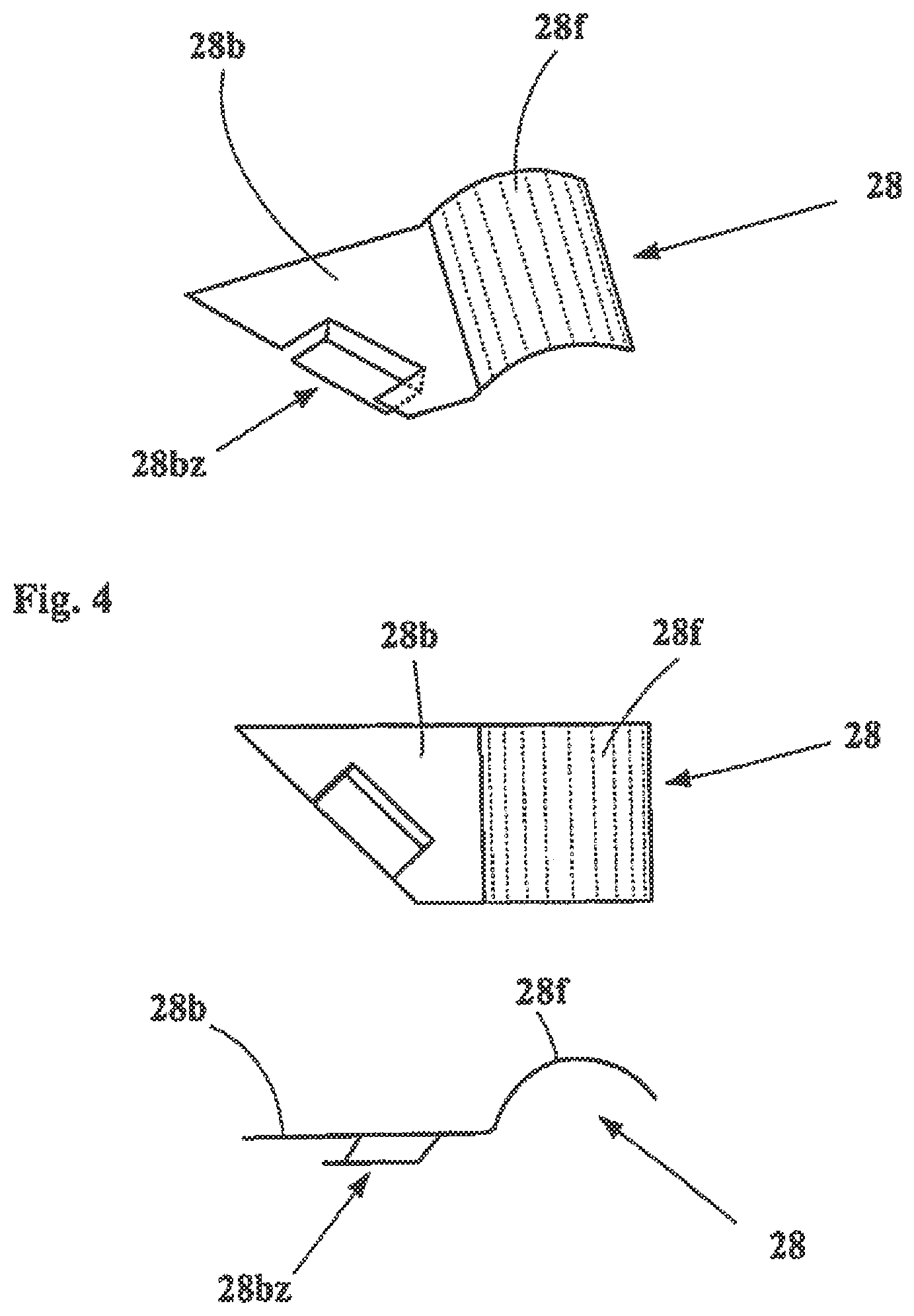
[0018] Preferred embodiments can provide that the lower, preferably horizontal, outside edge of the facade tile or/and the upper, preferably horizontal, outside edge of the facade tile is or are formed with a back ridge edge and a front ridge edge, wherein the receiver of the weight-supporting holder or the receiver of the upper support holder grips on the assigned back ridge edge.
[0019] In preferred embodiments the back ridge can be formed shorter than the front ridge, with the result that the back ridge is concealed by the front ridge.
[0020] In particularly preferred embodiments it is provided that the lower horizontal outside edge of the facade tile and the upper horizontal outside edge of the facade tile are in each case formed with a forward, i.e. front, ridge edge preferably by introduction of a corresponding cut into the lower horizontal outside edge and into the upper horizontal outside edge of the facade tile, wherein the weight-supporting holder gripping on the lower horizontal outside edge of the facade tile is arranged concealed behind the front ridge edge of the facade tile arranged on the lower horizontal outside edge and concealed behind the front ridge edge of the facade tile adjoining it at the bottom, formed on the upper horizontal outside edge.
[0021] Correspondingly, in embodiments which have upper support holders these can be arranged concealed behind a front ridge edge on the upper horizontal outside edge of the facade tile and a front ridge edge on the lower horizontal outside edge of the facade tile adjoining it at the top.
[0022] With regard to the design of the tile holders, it can be provided, for the purposes of a good engagement of the receiver of the tile holder with the facade tiles, in particular in the case of the vertical facade structure, that the receiver of the tile holder which engages with the vertical edge area of the facade tile is formed U-shaped, preferably as a double receiver with two U-shaped receivers facing away from each other. In a preferred development it can be provided that the vertical edges of the facade tile on which the tile holders grip with their receiver are formed on vertical outside edges of the facade tile. In particular, it can be provided that the vertical outside edges of the facade tile are formed as ridge edges, in each case with a back ridge edge and a front ridge edge, wherein the tile holders grip on the back ridge edge. In preferred embodiments of the facade tile one vertical outside edge has a back ridge edge and a front ridge edge but the other vertical outside edge has only a back ridge edge, wherein the tile holders in each case grip on the back ridge edge.
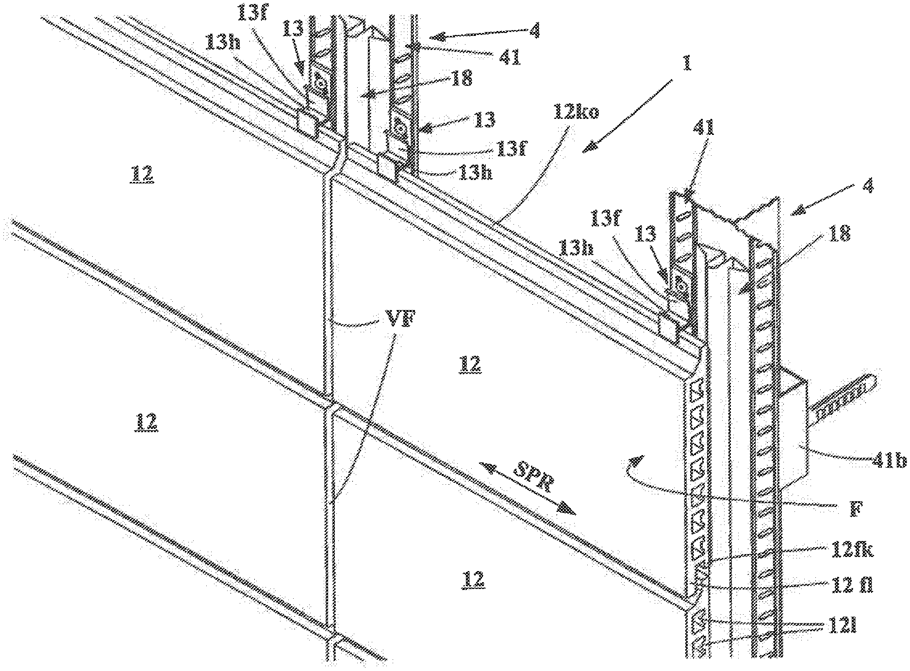
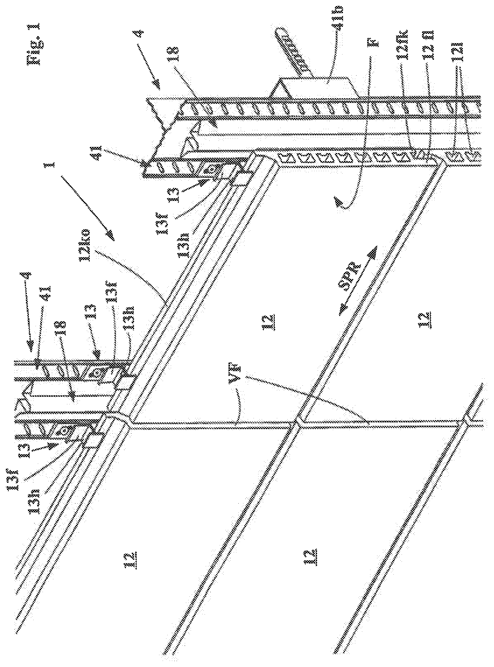
[0023] Preferred embodiments provide that the tile holder or/and the receiver of the tile holder is or are arranged concealed behind the assigned facade tile or behind the assigned facade tiles.
[0024] A particularly favourable mode of operation in the mounting of the facade tile results if it is provided that several tile holders, which engage with opposite vertical edges of the facade tiles--preferably opposite vertical edges of a horizontal row of facade tiles--wherein the support profile is arranged horizontally, are fastened, preferably detachably, to the support profile in horizontal alignment. Alternatively, it can also be provided that several tile holders, which engage with vertical edges of the facade tile--preferably vertical edges of facade tiles in a vertical row of facade tiles--wherein the support profile is arranged vertically, are fastened, preferably detachably, to a support profile in vertical alignment.
[0025] As an alternative or in addition to joint profiles, it can be provided that the facade tiles are impinged on by a press-on device for the purpose of a shake-proof arrangement, wherein it can be provided that the press-on device is formed by separate press-on elements, wherein each of the press-on elements has a compression spring device and acts directly only on an assigned facade tile.
[0026] With regard to the support and arrangement of the press-on elements, it can be provided that the press-on element is detachably fastened to a support profile directly or via a separate support. It can preferably be provided that the press-on element is arranged concealed behind an assigned facade tile and supported against the substructure. The arrangement of the press-on element can in each case be formed such that the press-on element grips on the back of the assigned facade tile in an area which is arranged at a distance from the tile holders gripping on the facade tile with their receivers.
[0027] With regard to the compression spring device, it can be provided that the press-on element has a press-on spring clip for cooperating with the back of the assigned facade tile. The press-on spring clip cooperates, with the outside of the spring clip, with the back of the facade tile. The press-on spring clip can have a fluting on the outside in particular embodiments.
[0028] With regard to the fastening of the press-on elements to or in the substructure, it is advantageous if it is provided that the press-on element has a fastening section, which is fastened to the support profile by means of a screw connection and/or rivet connection and/or a clamping connection and/or a plug-in device engaging in a positive-locking manner in a slot in the support profile.
[0029] The subject-matter of independent main claim 13 represents a further solution according to the invention. Main claim 13 provides a construction set for the production of a facade structure, selectively as a vertical facade structure or as a horizontal facade structure.
[0030] Embodiments of the facade structure as a horizontal facade structure, i.e. with an arrangement of the facade tile aligned with the extrusion direction horizontal, are possible using the identical tile holders, which then in each case conventionally grip on the lower and upper edge areas of the facade tiles. The identical support profiles can be used to fasten the tile holders, wherein the support profiles are to be arranged simply rotated by 90.degree. in the substructure. In this case the fastening and arrangement of the tile holders on the support profiles can be effected in the same way as in the embodiment in which the facade tiles are arranged in vertical format.
[0031] The construction set according to main claim 13 is a construction set for the production of a facade structure, preferably a curtain-wall back-ventilated facade structure, either as a vertical facade structure or as a horizontal facade structure. Facade tiles with ridges and/or extruded facade tiles are used. In the vertical facade structure the facade tiles are aligned with the longitudinal extent of their ridges and/or the extrusion direction vertical. In the horizontal facade structure the facade tiles are aligned with the longitudinal extent of their ridges and/or the extrusion direction horizontal.
[0032] The construction set comprises the following components:
[0033] several support profiles, which are fastenable to a building wall or to the floor directly or via intermediate supports to form a substructure;
[0034] several tile holders with a receiver for engaging with an edge section of the facade tiles, wherein the tile holders are formed for fastening to one of the support profiles;
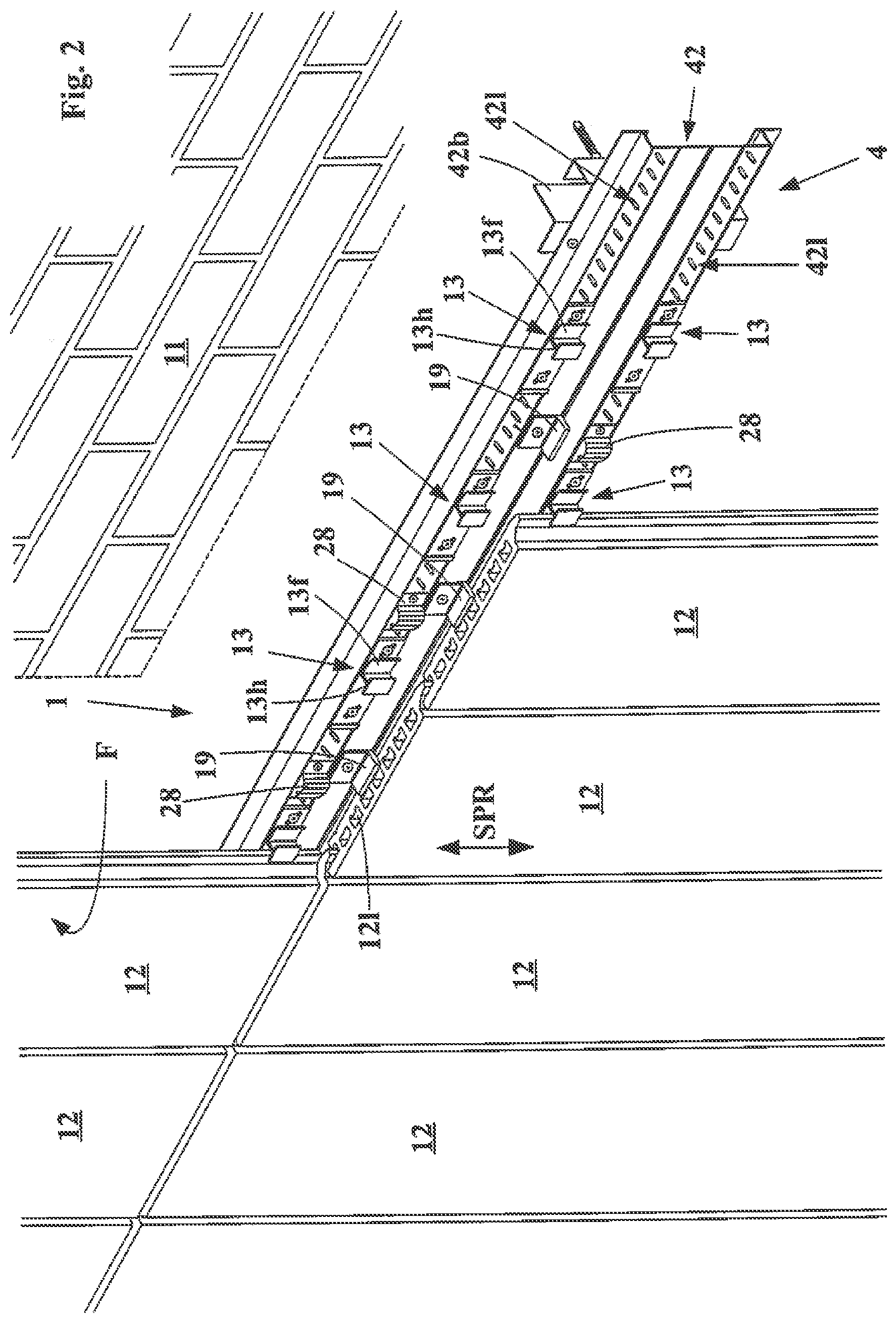
[0035] several weight-supporting holders with a receiver for bearing the facade tiles, wherein the weight-supporting holder is formed for fastening to one of the support profiles;
[0036] extruded facade tiles formed with ridges and/or extruded, preferably made of ceramic material, e.g. clay material.
[0037] It is provided that:
[0038] the following components are necessarily used to produce a vertical facade structure: a), b), c), d); and
[0039] the following components are necessarily used to produce a horizontal facade structure: a), b), d).
[0040] Embodiments of the construction set which have the following components as additional details are also possible: several upper support holders with a receiver for gripping on an upper edge of the facade tile, wherein the upper support holders are formed for fastening to one of the support profiles.
[0041] In preferred embodiments of the construction set it is provided that press-on devices (28), which are in each case assigned to only one facade tile, which are preferably formed as separate press-on elements or which are in each case assigned to several facade tiles (12), preferably formed as a joint profile, are used to produce a vertical facade structure and/or to produce a horizontal facade structure.
[0042] Furthermore, the invention achieves the stated object also with a method according to the further independent main claim 14. This is a method for producing a facade structure as a vertical facade structure and/or as a horizontal facade structure using in part identical components. The method of claim 14 is a method for producing a facade structure, preferably a curtain-wall back-ventilated facade structure, in each case made of facade tiles formed with ridges and/or extruded, preferably made of ceramic material, e.g. clay material, as a vertical facade structure or as a horizontal facade structure, wherein the vertical facade structure is formed in such a way that the facade tiles are arranged on a substructure arranged in front of a building wall via tile holders, with the longitudinal extent of their ridges and/or the extrusion direction (SPR) aligned vertically, and wherein the horizontal facade structure is formed in such a way that the facade tiles are arranged on a substructure arranged in front of a building wall via tile holders, with the longitudinal extent of their ridges and/or the extrusion direction (SPR) aligned horizontally.
[0043] It is provided that:
[0044] the following components are used to produce the vertical facade structure: [0045] substructure components comprising support profiles, which are fastenable to the building wall or to the floor directly or via intermediate supports to form the substructure; [0046] tile holders with a receiver for engaging with an edge section of the facade tiles, wherein the tile holders are formed for fastening to one of the support profiles; [0047] weight-supporting holders with a receiver for bearing the facade tiles, wherein the weight-supporting holder is formed for fastening to one of the support profiles; and [0048] extruded facade tiles; and
[0049] the following components are used to produce the horizontal facade structure: [0050] substructure components comprising support profiles, which are fastenable to a building wall or to the floor directly or via intermediate supports to form a substructure; [0051] tile holders with a receiver for engaging with an edge section of the facade tiles, wherein the tile holders are formed for fastening to one of the support profiles; and [0052] extruded facade tiles.
[0053] The above-named method according to claim 14 can preferably be a method for producing a facade structure, preferably a curtain-wall back-ventilated facade structure, in at least one embodiment as a vertical facade structure and in at least one embodiment as a horizontal facade structure, in each case made of facade tiles formed with ridges and/or extruded, preferably made of ceramic material, e.g. clay material.
[0054] Moreover, the invention achieves the stated object also with the universal use of an identical support profile with identical support holders both in a vertical facade structure and in a horizontal facade structure. Independent main claim 15 is in this sense a use of support profiles with tile holders for producing a facade structure, preferably a curtain-wall back-ventilated facade structure, wherein the facade structure has:
[0055] a substructure formed of the support profiles, which is arranged in front of a building wall and anchored fixedly in the floor and/or in the building wall, and
[0056] facade tiles formed with ridges and/or extruded, preferably made of ceramic material, e.g. clay material, which are fastened to the substructure via tile holders,
[0057] wherein the tile holders are fastened, preferably detachably, to at least some of the support profiles of the substructure, wherein the tile holders have receivers, which grip on edge areas of the facade tiles to hold the tile holders;
[0058] It is provided that:
[0059] the support profiles to which the tile holders are fastened are arranged in the vertical facade structure in a first position, which is specific to the vertical facade structure, and
[0060] the support profiles to which the tile holders are fastened are arranged in the horizontal facade structure in a second position, which is specific to the horizontal facade structure, wherein the second position is arranged rotated by 90.degree. relative to the first position.
[0061] In the vertical facade structure the facade tiles are arranged on a substructure arranged in front of a building wall via tile holders, with the longitudinal extent of their ridges and/or the extrusion direction aligned vertically.
[0062] In the horizontal facade structure the facade tiles are arranged on a substructure arranged in front of a building wall via tile holders, with the longitudinal extent of their ridges and/or the extrusion direction aligned horizontally.
BRIEF DESCRIPTION OF THE DRAWINGS
[0063] The invention is now explained in more detail with reference to figures.
[0064] There are shown in:
[0065] FIG. 1a first facade structure as a horizontal facade structure in a perspective view;
[0066] FIG. 1a the facade structure of FIG. 1 in a schematic side view;
[0067] FIG. 2 a second facade structure as a vertical facade structure in a perspective view;
[0068] FIG. 3 a press-on element from the facade structure of FIG. 2 in a detail representation;
[0069] FIG. 4 a press-on element modified compared with FIG. 3;
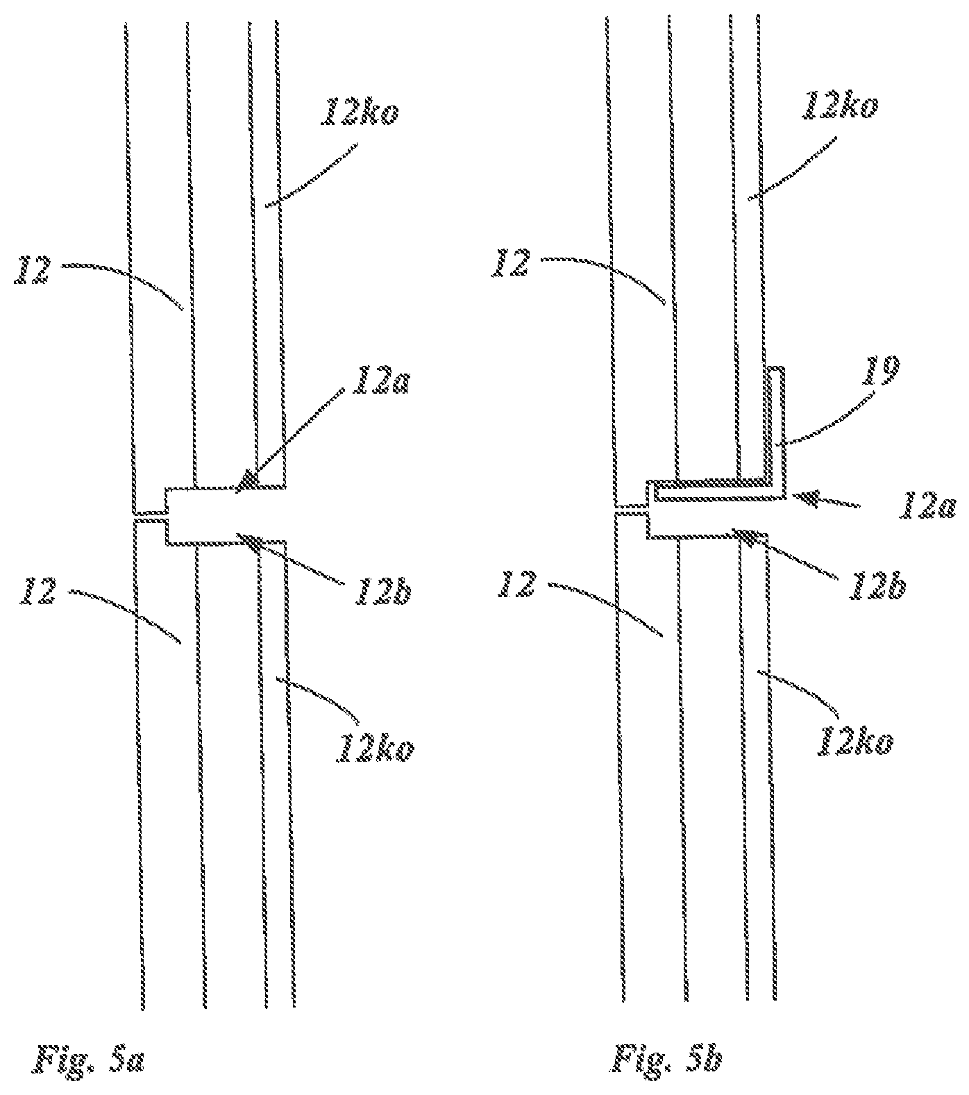
[0070] FIG. 5a schematic side view of the facade structure as a vertical facade structure from FIG. 2 with cuts into the lower or upper edge of the facade tile for a weight-supporting holder;
[0071] FIG. 5b schematic side view of the facade structure as a vertical facade structure from FIG. 2 with a weight-supporting holder in the cuts.
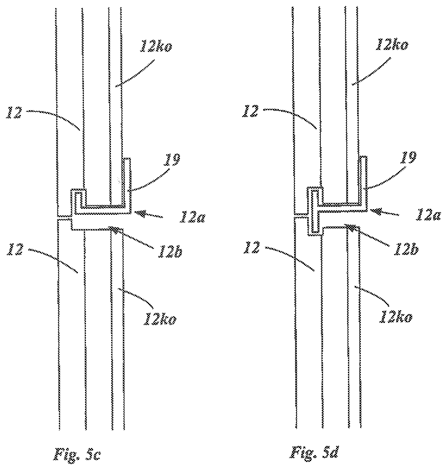
[0072] FIG. 5c schematic side view of the facade structure as a vertical facade structure from FIG. 2 with a second design of the cuts and U-shaped angled brackets.
[0073] FIG. 5d schematic side view of the facade structure as a vertical facade structure from FIG. 2 with a third design of the cuts and H-shaped angled brackets.
DETAILED DESCRIPTION
[0074] FIG. 1 shows a first embodiment of a facade structure 1 and FIG. 2 shows a second embodiment of a facade structure 1. Correspondingly, they are in each case a facade structure with facade tiles 12, which are arranged on a substructure 4 in front of a building wall 11. The facade tiles 12 are in each case extruded tiles made of ceramic material which are rectangular in outline. The tiles are rectangular in outline and have parallel elongated holes 12l running in the extrusion direction SPR. The elongated holes 12l are arranged evenly distributed over the outline face of the tile in the longitudinal centre plane of the tiles at an identical mutual distance. The facade tiles 12 are arranged in the facade structure of FIGS. 1 and 2 in each case such that their fronts are aligned with each other in each case, forming a common front plane F.
[0075] Regarding now the differences between the two embodiments in FIGS. 1 and 2:
[0076] In the first embodiment of the facade structure 1 represented in FIG. 1 the facade tiles 12 are arranged in the horizontal format, i.e. the facade tiles 12 are arranged in the facade structure such that their extrusion direction SPR is arranged horizontally. In contrast, in the second embodiment of the facade structure represented in FIG. 2 the facade tiles 12 are arranged in vertical format, i.e. the facade tiles 12 are arranged in this facade structure such that their extrusion direction SPR is arranged vertically. The facade tiles 12 are designed identically in both embodiments of the facade structure. They are simply in horizontal format in FIG. 1 and in vertical format in FIG. 2, i.e. arranged rotated by 90.degree. about their vertical axis.
[0077] In the case of the first facade structure in FIG. 1 the substructure 4 is formed by vertical support profiles 41. Tile holders 13 are fastened to the support profiles 41 in vertical rows. The tile holders 13 in each case have an H-shaped receiver 13h. Facade tiles 12 arranged in each case in a vertical line engage in the H-shaped receivers 13h with their back ridge edges facing the receiver. The back ridge edges are offset relative to the forward front of the facade tile backwards in the direction of the building wall 11. The facade tiles 12 in FIG. 1 have a single head ridge 12ko in each case on their upper edge; this is formed in the back plane. On their lower edge the facade tiles have in each case a longer base ridge 12fl in a front plane and a shorter base ridge 12fk in the back plane. The head ridge 12ko of the lower facade tile 12 engages in the lower receiver of the H-shaped receiver 13h. The back short base ridge 12fk of the upper facade tile 12 engages in the upper receiver, wherein the longer base ridge 12fl covers the H-shaped receiver 13h on the front.
[0078] The facade tiles 12 are thus held in the facade structure in FIG. 1 via the tile holders 13 in that tile holders 13 grip in each case on the upper edge and on the lower edge with their H-shaped receivers 13h, namely on the upper edge of the facade tile with the lower receiver of the H-shaped receiver and on the lower edge of the facade tile with the upper receiver of the H-shaped receiver.
[0079] As can be seen in FIG. 1, vertical joints VF are formed between horizontally adjacent facade tiles. Joint profiles 18 engage in these joints. The joint profiles 18 are formed as spring steel sheet profiles with a substantially .OMEGA.-shaped cross section with angled base arms. The joint profile 18 is arranged between the front of the support profile 41 and the back of the facade tiles horizontally adjacent to each other via the joint. The joint profile 18 extends along the longitudinal centre axis of the support profile 41 over several horizontal rows of the facade tiles. The joint profile 18 impinges on the facade tiles such that they are pushed into the receivers 13h of the tile holders 13 in the direction towards the front of the facade structure and come to bear against the inside of the front arm of the U-shaped receivers of the tile holders 13. The joint profile 18 thus ensures a shake-proof arrangement of the facade tiles in the tile holders 13.
[0080] In the case of the tile holders 13 used in the embodiment in FIG. 1, clip-shaped stainless steel springs 13f made of sheet steel, which engage in assigned rearward grooves in the facade tiles and thus prevent the facade tiles from lifting off, are integrated in the receivers of the tile holders. Such stainless steel springs 13f in receivers of tile holders are described e.g. in EP 1 878 847 A2.
[0081] In the case of the second embodiment of the facade structure represented in FIG. 2--as stated this is a vertical facade structure--the substructure 4 is formed by horizontal support profiles 42. Tile holders 13 are fastened to the support profiles 42 in horizontal rows. The tile holders 13 are constructed identically to the tile holders in FIG. 1. They have H-shaped receivers 13h with clip-shaped stainless steel springs 13f integrated therein. In particular in the case of this use of the tile holders 13 in the vertical facade structure, in particular embodiments clip-shaped stainless steel springs 13f can be arranged in the H-shaped receivers in both receivers in order to hold the engaging ridge edge. The tile holders 13 grip with their H-shaped receivers on the vertical side edges of the facade tiles 12 arranged in vertical format. In each case the back ridge edges of the facade tiles engage in the receivers of the tile holders 13. The engagement of the lateral ridge edges in FIG. 2 in the H-shaped receivers of the tile holders 13 is effected in a manner corresponding to the engagement of the upper and lower ridge edges in the case of the horizontal facade structure in FIG. 1. The horizontal support profiles 42 in FIG. 2 are preferably identical components to those in the case of the vertical support profiles 41 of FIG. 1, wherein those in FIG. 2 are simply arranged in a horizontal arrangement, i.e. rotated 90.degree. about the vertical axis. The tile holders 13 in FIG. 2 are preferably also tile holders which are formed identically and are arranged on the support profiles 42 identically to the tile holders 13 in FIG. 1. However, the tile holders 13 in the facade structure in FIG. 2 differ from the tile holders 13 in the facade structure in FIG. 1 with respect to the function. In FIG. 2 the tile holders 13 simply bear the wind loads, as they simply grip laterally with their receivers on the vertical edges of the facade tiles.
[0082] In the vertical facade structure in FIG. 2 separate angled brackets 19 with an angular L-shaped receiver are attached to the support profiles 42 to support the weight loads. The fastening of the angled brackets 19 to the support profiles 42 is effected, as shown in FIG. 2, via a screw or rivet connection on the front of the support profile 42 outside the fastening rows of elongated holes, in which the angled brackets 19 are fastened via a rivet connection. The facade tiles 12 bear with their lower edges on the angled brackets 19. For this, the free arm of the angular L-shaped receiver of the angled brackets 19 grips underneath the lower edge of the facade tiles 12, preferably without protruding at the front (see FIG. 5).
[0083] As shown in FIG. 5, the angled bracket 19 gripping on the lower edge of the facade tile 12 can be concealed by a ridge which is formed by a lower cut 12a on the lower edge of this facade tile, and additionally by a ridge which is formed by an upper cut 12b on the upper edge of the facade tile 12 adjoining it at the bottom. The support holder 19 engages between the lower horizontal edge of the upper facade tile and the upper horizontal edge of the facade tile adjoining it at the bottom. At the front, the angled bracket 19 is concealed by the ridge which is formed as a front ridge in each case by the lower cut 12a on the lower horizontal edge and by the upper cut 12b on the upper horizontal edge of the facade tile.
[0084] As shown in FIG. 5c, in embodiments modified compared with FIG. 2, the angled bracket 19 can also be formed bent, i.e. in the broadest sense with a U-shaped cross section, and can engage in a groove cut into the lower edge of the facade tile 12. The lower edge of the facade tiles can be formed in the broadest sense with a front ridge and a back ridge and the angled bracket 19 can grip around the back ridge edge.
[0085] In embodiments modified compared with FIG. 2, the upper edge of the facade tiles 12 can also be formed with a comparable groove or with a front ridge and a back ridge (see FIG. 5d). The angled bracket 19 can have a bend on its underside and can correspondingly engage in the lower edge of the facade tiles, i.e. can engage in the groove or grip around the back ridge. Alternatively, a separate upper support holder, which is fastened to the support profile 42 separately, can also be provided for the engagement in the upper edge of the facade tiles 12. For this, the support holder can be formed with a substantially L-shaped cross section with a bend on its underside.
[0086] For the shake-proof arrangement of the facade tiles 12 in the H-shaped receivers 13h of the tile holders 13, press-on elements 28 arranged in each case concealed behind the facade tiles 12 are provided in the vertical facade structure in FIG. 2 instead of the joint profiles 18 used in FIG. 1. The press-on elements 28 cooperate in each case individually with a facade tile 12, i.e. one separate press-on element 28 per facade tile 12. The press-on elements 28 are formed of spring steel sheet. They have a spring clip 28f and a fastening section 28b. The press-on element 28 is arranged between the front of the support profile 42 and the back of the facade tile 12 and acts on the back of the facade tile 12 with the outside of the spring clip 28f and impinges on the facade tile in the direction towards the front of the facade structure. The press-on elements 28 are fastened to the support profile 42 with their fastening section 28b in the facade structure represented in FIG. 2, namely via a rivet connection in an elongated hole of the row of elongated holes, in which the tile holders 13 are also fastened.
[0087] The fastening of the press-on elements 28 is effected in the elongated holes of the row of elongated holes 42l, which is formed in the support profile. The tile holders 13 are also fastened in the same row of elongated holes 42l, namely in the same way as the press-on elements 28. In the same way, in the case of the facade structure in FIG. 1 the tile holders 13 are also fastened in the corresponding row of elongated holes 41l in the support profile 41. This is a fastening such as is known from EP 2 186 966 A2.
[0088] Unlike the press-on element 28 used in FIG. 2, the modified embodiment of the press-on element 28 represented in FIG. 4 has a fastening section, which is formed as a clamping lug. For the fastening, the clamping lug cooperates with the elongated hole of the row of inclined elongated holes 42l selected for the respective position in the profile support 42, namely forming a clamping connection. For this, the clamping lug, as represented in the detail representation in FIG. 4, has an inclined end edge, in which a Z-shaped bend is formed. The incline of the end edge corresponds to the angle of inclination of the elongated hole of the row of elongated holes. In the clamping position the Z-shaped bend engages in the elongated hole and is pushed in as far as it will go, with the result that the Z-shaped bend grips behind the section of the support profile behind the elongated hole. The press-on element 28 in the different embodiments of FIGS. 3 and 4 can also be used in the case of the horizontal facade structure represented in FIG. 1, namely fastened to the support profile 41 in a manner corresponding to what was described above for the facade structure of FIG. 2. The press-on element 28 can thus replace the joint profile 18 or be used in addition to the joint profile 18.
LIST OF REFERENCE NUMBERS
[0089] 1 facade structure [0090] 4 substructure [0091] 41 support profile (FIG. 1) [0092] 41b fastening section of 41 [0093] 41l row of elongated holes in 41 [0094] 42 support profile (FIG. 2) [0095] 42l row of elongated holes in 42 [0096] 11 building wall [0097] 12 facade tile [0098] 12a lower cut for a weight-supporting holder/angled bracket [0099] 12b upper cut for a weight-supporting holder/angled bracket [0100] 12l elongated hole [0101] 12ko head ridge=single back ridge edge at the head [0102] 12fl base ridge long=front ridge edge at the base [0103] 12fk base ridge short=back ridge edge at the base [0104] 13 tile holder [0105] 13h H-shaped receiver of the tile holder [0106] 13f stainless steel spring [0107] 18 joint profile [0108] 19 angled bracket, weight-supporting holder [0109] 28 press-on spring element [0110] 28f spring clip [0111] 28b fastening section [0112] 28bl fastening hole [0113] 28bz Z-shaped bend [0114] SPR extrusion direction [0115] F front plane of the facade structure [0116] VF vertical joint
* * * * *
D00000
D00001
D00002
D00003
D00004
D00005
D00006
D00007
XML
uspto.report is an independent third-party trademark research tool that is not affiliated, endorsed, or sponsored by the United States Patent and Trademark Office (USPTO) or any other governmental organization. The information provided by uspto.report is based on publicly available data at the time of writing and is intended for informational purposes only.
While we strive to provide accurate and up-to-date information, we do not guarantee the accuracy, completeness, reliability, or suitability of the information displayed on this site. The use of this site is at your own risk. Any reliance you place on such information is therefore strictly at your own risk.
All official trademark data, including owner information, should be verified by visiting the official USPTO website at www.uspto.gov. This site is not intended to replace professional legal advice and should not be used as a substitute for consulting with a legal professional who is knowledgeable about trademark law.