Loader Working Device
Yang; Jinxia ; et al.
U.S. patent application number 16/614001 was filed with the patent office on 2020-03-12 for loader working device. The applicant listed for this patent is Guangxi LiuGong Machinery Co., Ltd.. Invention is credited to Mingzhi Lin, Edward Wagner, Xuan Xiao, Jinxia Yang.
| Application Number | 20200080279 16/614001 |
| Document ID | / |
| Family ID | 62866543 |
| Filed Date | 2020-03-12 |
| United States Patent Application | 20200080279 |
| Kind Code | A1 |
| Yang; Jinxia ; et al. | March 12, 2020 |
Loader Working Device
Abstract
The disclosure relates to a loader working device for solving the problem of arranging the parts used in a vertical lifting mechanism of an existing loader. The loader working device comprises an accessory, an accessory overturning mechanism, and an accessory lifting mechanism including a movable arm, a movable arm oil cylinder, a front link rod and a rear link rod. The accessory lifting mechanism does not cause the accessory to interfere with a rocker arm and a front axle package of the loader working device. A connecting and mounting point of the movable arm and the accessory can be moved backwardly, thus improving a digging force and a tilting load at a low position of the loader working device.
| Inventors: | Yang; Jinxia; (Liuzhou, Guangxi, CN) ; Lin; Mingzhi; (Liuzhou, Guangxi, CN) ; Xiao; Xuan; (Liuzhou, Guangxi, CN) ; Wagner; Edward; (Liuzhou, Guangxi, CN) | ||||||||||
| Applicant: |
|
||||||||||
|---|---|---|---|---|---|---|---|---|---|---|---|
| Family ID: | 62866543 | ||||||||||
| Appl. No.: | 16/614001 | ||||||||||
| Filed: | January 25, 2019 | ||||||||||
| PCT Filed: | January 25, 2019 | ||||||||||
| PCT NO: | PCT/CN2019/073111 | ||||||||||
| 371 Date: | November 15, 2019 |
| Current U.S. Class: | 1/1 |
| Current CPC Class: | E02F 3/283 20130101; E02F 3/3408 20130101; E02F 3/38 20130101; E02F 3/342 20130101; E02F 3/422 20130101; E02F 3/431 20130101; E02F 9/0841 20130101; E02F 3/42 20130101; E02F 3/3405 20130101 |
| International Class: | E02F 3/42 20060101 E02F003/42; E02F 3/34 20060101 E02F003/34 |
Foreign Application Data
| Date | Code | Application Number |
|---|---|---|
| Jan 26, 2018 | CN | 201810076343.4 |
Claims
1. A loader working device, comprising: a front frame, wherein a front end of the front frame is provided with a support; an accessory; an accessory lifting mechanism connected between the accessory and the front frame, wherein the accessory lifting mechanism is symmetrical left and right about a central plane, and wherein the accessory lifting mechanism comprises: a movable arm on each of a left side and a right side of the accessory lifting mechanism, wherein a movable arm beam is fixedly connected between the movable arms; and a movable arm oil cylinder on each of the left side and the right side of the accessory lifting mechanism, wherein one end of the movable arm oil cylinder is hinged to a point A on one of the movable arms, and wherein another end of the movable arm oil cylinder is hinged to a point B on the front frame; an accessory overturning mechanism connected between the accessory and the front frame; a front link rod, wherein a front end of the front link rod is hinged to a point C on the support, and wherein a rear end of the front link rod is hinged to a point D on one of the movable arms; and a rear link rod, wherein an upper end of the rear link rod is hinged to a point E at the rear end of one of the movable arms, and wherein a lower end of the rear link rod is hinged to a point F on the front frame; wherein: a convex quadrilateral is formed by connecting lines between projection points of the points A, E, F, and D on the central plane; the connecting lines between projection points of the points C, E, and D on the central plane form a triangle; and a projection point of the point D is located below a connecting line of the projection points of the point C and the point E.
2. The loader working device according to claim 1, wherein the movable arm is provided with a front link rod hinge arm extending downwardly, wherein the rear end of the front link rod is hinged to a lower end of the front link rod hinge arm, and wherein the front link rod hinge arm is located between the movable arm oil cylinder and the support at the front end of the front frame.
3. The loader working device according to claim 1, wherein: the accessory overturning mechanism comprises a pulling rod, a rocker arm, an overturning oil cylinder, a three-hinge point holder, and a self-leveling link rod; rear link rods at the left side and the right side are connected into an H shape by a middle beam; a middle portion of the rocker arm is hinged to the movable arm beam; an upper end of the rocker arm is hinged to a rear end of the pulling rod; a front end of the pulling rod is hinged to the accessory; a lower end of the rocker arm is hinged to a front end of the overturning oil cylinder; a rear end of the overturning oil cylinder is hinged to a point G of the three-hinge point holder; a point H of the three-hinge point holder is hinged to the middle beam; a point I of the three-hinge point holder is hinged to an upper end of the self-leveling link rod; a lower end of the self-leveling link rod is hinged to a point L on the front frame; the point G is located above the point I; and the point H is located at a rear side of a connecting line between the point G and the point I.
4. The loader working device according to claim 2, wherein: the accessory overturning mechanism comprises a pulling rod, a rocker arm, an overturning oil cylinder, a three-hinge point holder and a self-leveling link rod; rear link rods at the left side and the right side are connected into an H shape by a middle beam; a middle portion of the rocker arm is hinged to the movable arm beam; an upper end of the rocker arm is hinged to a rear end of the pulling rod; a front end of the pulling rod is hinged to the accessory; a lower end of the rocker arm is hinged to a front end of the overturning oil cylinder; a rear end of the overturning oil cylinder is hinged to a point G of the three-hinge point holder; a point H of the three-hinge point holder is hinged to the middle beam; a point I of the three-hinge point holder is hinged to an upper end of the self-leveling link rod; a lower end of the self-leveling link rod is hinged to a point L on the front frame; the point G is located above the point I; and the point H is located at a rear side of a connecting line between the point G and the point I.
5. The loader working device according to claim 3, wherein connecting lines of the point G, the point H, and the point I of the three-hinge point holder form an equilateral triangle.
6. The loader working device according to claim 3, wherein connecting lines between projection points of the point I, the point H, the point F, and the point L on the central plane form a parallelogram.
7. The loader working device according to claim 5, wherein the self-leveling link rod is L-shaped, and wherein an upper section thereof is bent backwardly.
8. The loader working device according to claim 3, wherein the overturning oil cylinder is located below the movable arm beam.
Description
TECHNICAL FIELD
[0001] The present disclosure relates to a working device, and more particularly, to a vertically lifted loader working device.
BACKGROUND
[0002] A working device is one of important components on a construction machinery loader, and different functions of a whole machine can be realized through different working device mechanisms. At present, a common working device mechanism of the loader includes a six-link rod mechanism and an eight-link rod mechanism. The biggest market share is the six-link rod mechanism, but this type of working device mechanism has the problem that a tilting ability of the whole machine is insufficient, the increase of tilting will lead to an increase in the weight of the whole machine, the insufficient ease of operation and an increase in oil consumption of the whole machine. With the improvement of technical ability of the loader, the vertical lifting mechanism solves this problem well, the vertical lifting mechanism has a short load moment arm in a lifting process, which can realize a larger tilting load with smaller weight of the whole machine and make the operation process of the whole machine more stable. At the same time, due to the short load moment arm, useless work in the lifting process of the working device is reduced, and the lifting ability of the working device is stronger. The currently used vertical lifting mechanism realizes all operation functions of the loader through three sets of four-link rod mechanisms, compared with other link mechanisms, the vertical lifting mechanism uses more parts, which are arranged in the middle of the working device with limited arrangement space. At present, an inverted bucket mechanism used in vertical lifting, an overturning oil cylinder is connected to an upper hinge point of a rocker arm and a short link rod, with a high mounting position, which affects the visual field before operation. At the same time, the arrangement structure of the bucket mechanism is compact, at present, the arrangement requirements of the rocker arm are met through compressing a stroke of the overturning oil cylinder and changing an external structure of a bucket, for example, an opening angle of the bucket and a receiving angle of the bucket of the working device are reduced to meet the mechanism requirements, which affects the bucket performance and the operation performance of the working device to a certain extent, thus resulting in poor bucket filling rate, and the bucket needs to avoid the front hinge point of the rocker arm, making the bucket structure complicated.
SUMMARY
[0003] The technical problem to be solved by the present disclosure is to provide a loader working device for vertical lifting aiming at the problem that a vertical lifting mechanism of existing loader uses more parts, which are arranged in the middle of the working device and have limited arrangement space.
[0004] The technical solution of the present disclosure to achieve the purpose thereof is as follows: a loader device is arranged, which comprises an accessory, an accessory lifting mechanism connected between the accessory and a front frame of the loader, and an accessory overturning mechanism, wherein the accessory lifting mechanism is symmetrical left and right about a central plane, and comprises a movable arm and a movable arm oil cylinder on left and right sides; one end of the movable arm oil cylinder is hinged to a point A on the movable arm, the other end is hinged to a point B on the front frame, and a movable arm beam is fixedly connected between the two movable arms; the loader working device further comprises a front link rod and a rear link rod; a front end of the front frame is provided with a support;
[0005] a front end of the front link rod is hinged to a point C on the support, and a rear end of the front link rod is hinged to a point D on the movable arm;
[0006] an upper end of the rear link rod is hinged to a point E at the rear end of the movable arm, and a lower end is hinged to a point F on the front frame; and
[0007] a convex quadrilateral is formed by connecting lines between projection points of the hinge points A, E, F and D on a central plane; the connecting lines between projection points of the hinge points C, E and D on the central plane form a triangle, and a projection point of the point D is located below the connecting line of the projection points of the point C and the point E. In the present disclosure, the accessory lifting mechanism is formed by superposing two four-link rods to realize vertical lifting, and a first four-link rod mechanism consisting of the movable arm, the rear link rod, the front frame and the movable arm oil cylinder realizes a lifting movement of the movable arm; and a second four-link rod consisting of the movable arm, the front link rod, the front frame and the movable arm oil cylinder realizes horizontal restraint in a lifting process, so that a distance between the accessory and a front wheel is basically kept unchanged in the lifting process, so as to realize vertical lifting. In the present disclosure, the accessory can be a loader bucket, a pallet fork or a holding fork, etc.
[0008] Preferably, in the loader working device above, the movable arm is provided with a front link rod hinge arm extending downwardly, the rear end of the front link rod is hinged to a lower end of the front link rod hinge arm, and the front link rod hinge arm is located between the movable arm oil cylinder and the support at the front end of the front frame.
[0009] Preferably, in the loader working device above, the accessory overturning mechanism comprises a pulling rod, a rocker arm, a overturning oil cylinder, a three-hinge point holder and a self-leveling link rod; the rear link rods at left and right sides are connected into an H shape by a middle beam, a middle portion of the rocker arm is hinged to the movable arm beam, an upper end of the rocker arm is hinged to a rear end of the pulling rod, a front end of the pulling rod is hinged to the accessory, a lower end of the rocker arm is hinged to a front end of the overturning oil cylinder, a rear end of the overturning oil cylinder is hinged to a G hinge point of the three-hinge point holder, an H hinge point of the three-hinge point holder is hinged to the middle beam, an I hinge point of the three-hinge point holder is hinged to an upper end of the self-leveling link rod, a lower end of the self-leveling link rod is hinged to an L hinge point on the front frame, the G hinge point is located above the I hinge point, and the H hinge point is located at a rear side of a connecting line between the G hinge point and the I hinge point. Preferably, a forward Z-shaped six-link rod consisting of the accessory, the pulling rod, the rocker arm, the movable arm, the overturning oil cylinder and the three-hinge point holder at the front end of the accessory overturning mechanism realizes an overturning action of the accessory, and controls an overturning angle of the accessory and a digging force of the accessory. The overturning oil cylinder can be mounted at the lower end of the rocker arm, and the pulling rod can be mounted at the upper end of the rocker arm, thus reducing a mounting height of the overturning oil cylinder and improving a front visual field. Meanwhile, an overturning movement direction of the accessory is consistent with a movement direction of the rocker arm, which is beneficial to increasing the overturning angle of the accessory. Preferably, a four-link rod mechanism consisting of the three-hinge point holder, the self-leveling link rod, the rear link rod and the front frame at the rear end of the accessory overturning mechanism realizes automatic leveling in an accessory overturning process, which is intended to solve the problem of asynchronous angle turnover of the lifting mechanism and the accessory overturning mechanism, and the four-link rod structure at the rear end controls the change of the accessory overturning angle in the lifting process of the lifting mechanism, so that the change of the accessory angle relative to the ground is smaller. The three-hinge point holder skillfully solves the connection problem of the overturning oil cylinder, the rear link rod and the self-leveling link rod, and reduces the assembly difficulty.
[0010] Preferably, in the loader working device above, connecting lines of the G hinge point, the H hinge point and the I hinge point of the three-hinge point holder form an equilateral triangle.
[0011] Preferably, in the loader working device above, connecting lines between projection points of the I hinge point, the H hinge point, the F hinge point and the L hinge point on a central plane form a parallelogram.
[0012] Preferably, in the loader working device above, the self-leveling link rod is L-shaped, and an upper section thereof is bent backwardly.
[0013] Preferably, in the loader working device above, the overturning oil cylinder is located below a movable arm beam.
[0014] Compared with the prior art, the forward overturning mechanism is used in the vertical lifting mechanism according to the present disclosure, the overturning movement direction of the rocker arm is consistent with that of the accessory, the overturning oil cylinder can be arranged at the lower end of the rocker arm, and the pulling rod can be connected to the upper end of the rocker arm, so that the overturning oil cylinder moves downwardly, the working field at the front end of the working device is improved, and better operation performance is provided for the user. According to the present disclosure, the forward accessory overturning mechanism used in the vertical lifting mechanism does not cause the accessory to interfere with the rocker arm and the front axle package, and the connecting and mounting point of the movable arm and the accessory can be moved backwardly, thus being beneficial to improving the digging force and the tilting load at the low position of the working device. The mechanism has the self-leveling link rod to ensure little change in the angle of the accessory during lifting. The rear link rod, the overturning oil cylinder and the self-leveling link rod can be connected and mounted by adopting the three-hinge point holder, thus greatly reducing the assembly difficulty and improving the assembly efficiency.
BRIEF DESCRIPTION OF THE DRAWINGS
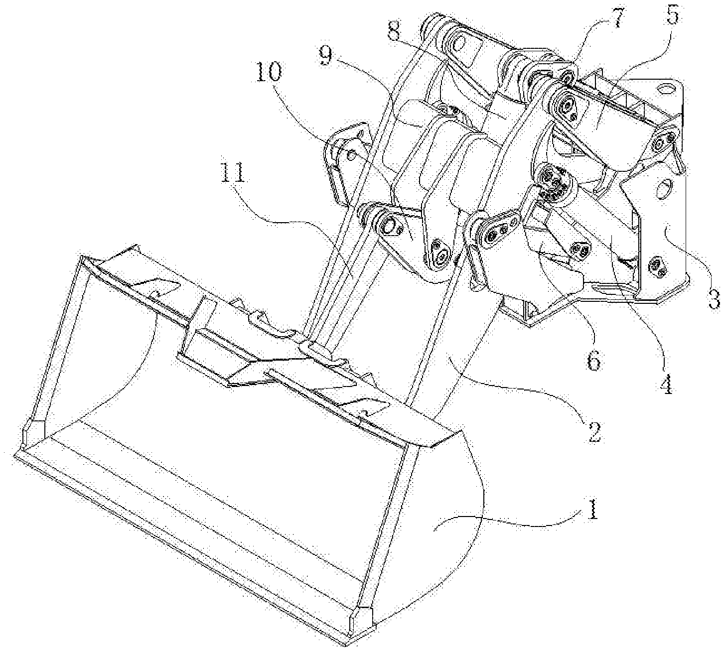
[0015] FIG. 1 is a structural diagram of a loader working device according to the present disclosure.
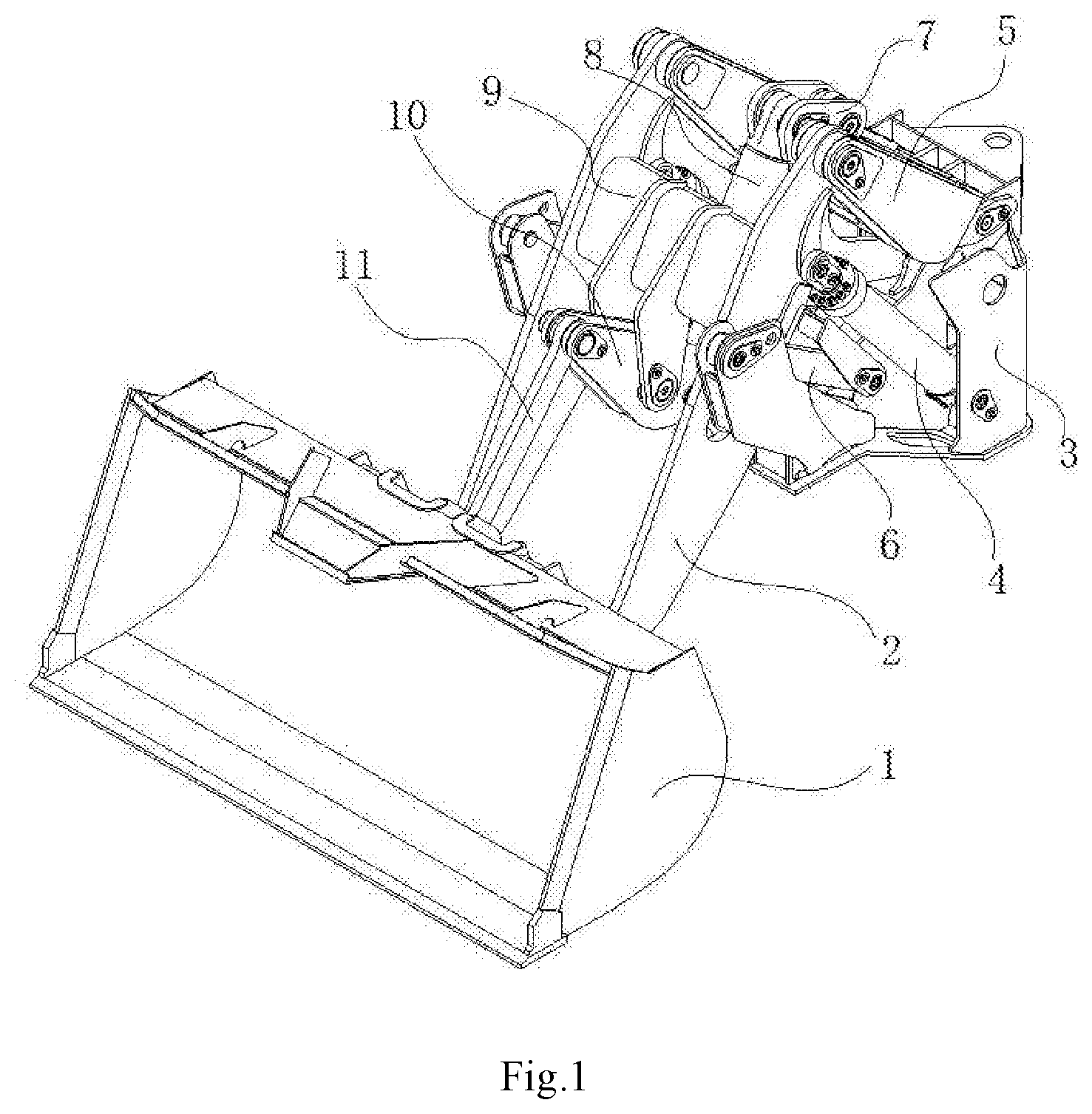
[0016] FIG. 2 is a side view of the loader working device according to the present disclosure.
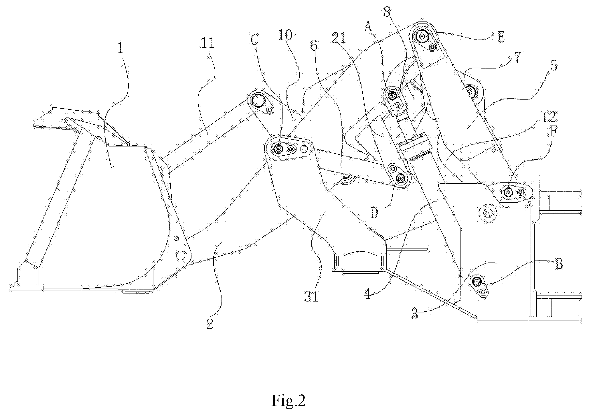
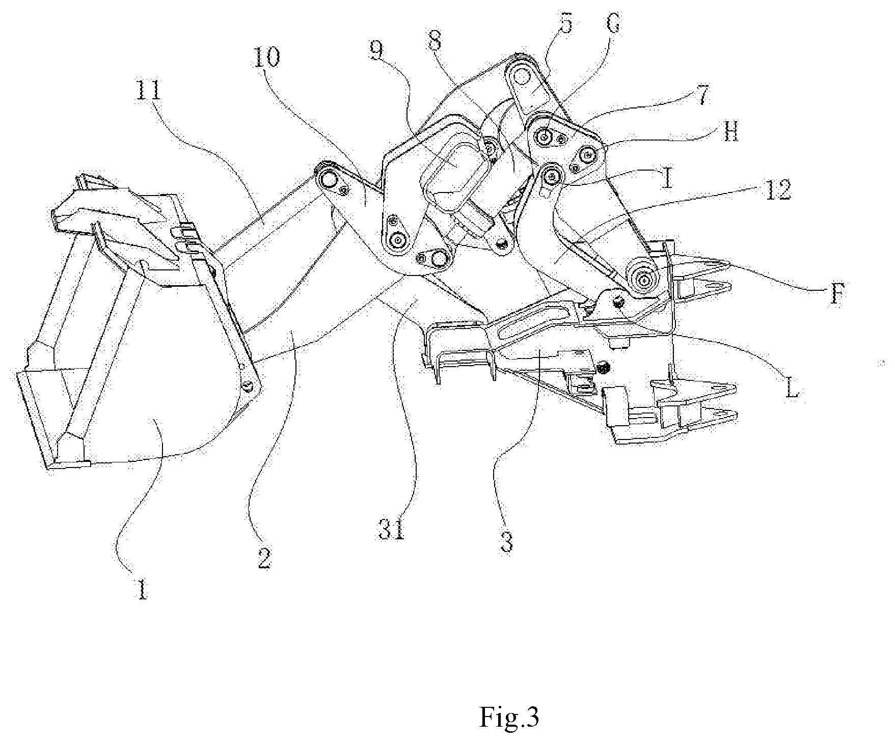
[0017] FIG. 3 is a sectional view of the loader working device according to the present disclosure.
DETAILED DESCRIPTION
[0018] The detailed embodiment is described with reference to the drawings.
[0019] As shown in FIG. 1 and FIG. 2, a loader working device in the embodiment is a loader bucket working device, which comprises an accessory bucket, a bucket lifting mechanism connected between the bucket and a front frame of the loader, and a bucket overturning mechanism, wherein the bucket lifting mechanism is symmetrical left and right about a vertical central plane, and comprises a movable arm 2, a movable arm oil cylinder 4, a front link rod 6 and a rear link rod 5 on left and right sides; and the two movable arms 2 are fixedly connected by a movable arm beam 9. A front end of the front frame 3 is provided with a support 31. One end of the movable arm oil cylinder 4 is hinged to a point A on the movable arm 2, and the other end is hinged to a point B on the front frame 3; a front end of the front link rod 6 is hinged to a point C on the support 31, the movable arm 2 is provided with a front link rod hinge arm 21 extending downwardly, a rear end of the front link rod 6 is hinged to a lower end of the front link rod hinge arm 21, and the hinge point is a point D. An upper end of the rear link rod 5 is hinged to a point E at the rear end of the movable arm, and a lower end is hinged to a point F on the front frame. A convex quadrilateral is formed by connecting lines between projection points of the hinge points A, E, F and D on a central plane; the connecting lines between projection points of the hinge points C, E and D on the central plane form a triangle, a projection point of the point D is located below the connecting line of the projection points of the point C and the point E, and the hinge point D is located between the movable arm oil cylinder 4 and the support 31 of the front frame at the front end.
[0020] As shown in FIG. 3, a bucket overturning mechanism comprises a pulling rod 11, a rocker arm 10, an overturning oil cylinder 8, a three-hinge point holder 7 and a self-leveling link rod 12; the rear link rods at left and right sides are connected into an H shape by a middle beam, a middle portion of the rocker arm 10 is hinged to the movable arm beam 9, an upper end of the rocker arm 10 is hinged to a rear end of the pulling rod 11, a front end of the pulling rod 11 is hinged to the bucket 1, a lower end of the rocker arm 10 is hinged to a front end of the overturning oil cylinder 8, a rear end of the overturning oil cylinder 8 is hinged to a G hinge point of the three-hinge point holder 7, an H hinge point of the three-hinge point holder 7 is hinged to the middle beam, an I hinge point of the three-hinge point holder 7 is hinged to an upper end of the self-leveling link rod 12, a lower end of the self-leveling link rod 12 is hinged to an L hinge point on the front frame 3, the G hinge point is located above the I hinge point, and the H hinge point is located at a rear side of a connecting line between the G hinge point and the I hinge point. Connecting lines of the G hinge point, the H hinge point and the I hinge point of the three-hinge point holder form an equilateral triangle. Connecting lines between projection points of the I hinge point, the H hinge point, the F hinge point and the L hinge point on a central plane form a parallelogram. The self-leveling link rod is L-shaped, and an upper section thereof is bent backwardly, thus avoiding interference between the self-leveling link rod and the middle beam connecting the two rear link rods. The overturning oil cylinder is located below the movable arm beam.
[0021] In the present disclosure, the bucket lifting mechanism is formed by superposing two four-link rods to realize vertical lifting, and a first four-link rod mechanism consisting of the movable arm 2, the rear link rod 5, the front frame 3 and the movable arm oil cylinder 4 realizes a lifting movement of the movable arm 2; and a second four-link rod consisting of the movable arm 2, the front link rod 6, the front frame 3 and the movable arm oil cylinder 4 realizes horizontal restraint in a lifting process, and controls a load moment arm to swing in a small range, so that a distance between the bucket 1 and a front wheel is basically kept unchanged in the lifting process, so as to realize vertical lifting.
[0022] A forward Z-shaped six-link rod consisting of the bucket 1, the pulling rod 11, the rocker arm 10, the movable arm 2, the overturning oil cylinder 8 and the three-hinge point holder 7 at the front end of the accessory overturning mechanism realizes an overturning action, and controls an overturning angle of the bucket and a digging force of the bucket. The overturning oil cylinder 8 is mounted at the lower end of the rocker arm 10, and the pulling rod 11 is mounted at the upper end of the rocker arm 10, thus reducing a mounting height of the overturning oil cylinder 8 and improving a front visual field. Meanwhile, an overturning movement direction of the bucket is consistent with a movement direction of the rocker arm 10, which is beneficial to increasing the overturning angle of the bucket. A four-link rod mechanism consisting of the three-hinge point holder 7, the self-leveling link rod 12, the rear link rod 5 and the front frame 3 at the rear end of the bucket overturning mechanism realizes automatic leveling in an overturning process, which solves the problem of asynchronous angle turnover of the bucket lifting mechanism and the bucket overturning mechanism, and the four-link rod structure at the rear end controls the change of the bucket overturning angle in the lifting process of the bucket lifting mechanism, so that the change of the bucket angle relative to the ground is smaller. The three-hinge point holder 7 skillfully solves the connection problem of the overturning oil cylinder 8, the rear link rod 5 and the self-leveling link rod 12, and reduces the assembly difficulty.
* * * * *
D00000
D00001
D00002
D00003
XML
uspto.report is an independent third-party trademark research tool that is not affiliated, endorsed, or sponsored by the United States Patent and Trademark Office (USPTO) or any other governmental organization. The information provided by uspto.report is based on publicly available data at the time of writing and is intended for informational purposes only.
While we strive to provide accurate and up-to-date information, we do not guarantee the accuracy, completeness, reliability, or suitability of the information displayed on this site. The use of this site is at your own risk. Any reliance you place on such information is therefore strictly at your own risk.
All official trademark data, including owner information, should be verified by visiting the official USPTO website at www.uspto.gov. This site is not intended to replace professional legal advice and should not be used as a substitute for consulting with a legal professional who is knowledgeable about trademark law.