Transfer Gearbox Device
LEGL; Lukas
U.S. patent application number 16/613770 was filed with the patent office on 2020-03-12 for transfer gearbox device. The applicant listed for this patent is Magna Powertrain GmbH & Co KG. Invention is credited to Lukas LEGL.
| Application Number | 20200079212 16/613770 |
| Document ID | / |
| Family ID | 62089722 |
| Filed Date | 2020-03-12 |


| United States Patent Application | 20200079212 |
| Kind Code | A1 |
| LEGL; Lukas | March 12, 2020 |
TRANSFER GEARBOX DEVICE
Abstract
A transfer gearbox device, comprising a differential gear with a crown wheel in a first oil chamber, and a friction clutch in a second oil chamber. The first oil chamber comprises a first oil sump and the second oil chamber comprises a second oil sump. A valve is between the first oil chamber and the second oil chamber. When the valve is open, oil can pass via the valve out of the first oil chamber into the second oil chamber. When the valve is closed, oil cannot pass via the valve out of the first oil chamber. When the valve is open, by rotating the crown wheel, oil is conveyed by the crown wheel from the first oil sump into a first oil collector and is guided therefrom via a first oil guide and via the valve to the friction clutch cool and/or to lubricate the friction clutch.
| Inventors: | LEGL; Lukas; (Graz, AT) | ||||||||||
| Applicant: |
|
||||||||||
|---|---|---|---|---|---|---|---|---|---|---|---|
| Family ID: | 62089722 | ||||||||||
| Appl. No.: | 16/613770 | ||||||||||
| Filed: | April 18, 2018 | ||||||||||
| PCT Filed: | April 18, 2018 | ||||||||||
| PCT NO: | PCT/EP2018/059869 | ||||||||||
| 371 Date: | November 14, 2019 |
| Current U.S. Class: | 1/1 |
| Current CPC Class: | F16H 57/04 20130101; F16H 57/045 20130101; F16H 57/0473 20130101; B60K 17/346 20130101; F16H 57/0453 20130101; F16H 57/0409 20130101; F16H 57/0483 20130101; F16D 13/74 20130101; F16H 57/0445 20130101; F16D 13/72 20130101; F16H 57/0457 20130101; F16H 57/0424 20130101; F16H 57/0435 20130101; F16H 57/0423 20130101 |
| International Class: | B60K 17/346 20060101 B60K017/346; F16H 57/04 20060101 F16H057/04 |
Foreign Application Data
| Date | Code | Application Number |
|---|---|---|
| May 18, 2017 | DE | 10 2017 208 433.2 |
Claims
1. A transfer gear device for a motor vehicle, comprising a differential gear with at least one crown wheel in a first oil chamber, and a friction clutch in a second oil chamber, wherein the first oil chamber comprises a first oil sump and the second oil chamber comprises a second oil sump, wherein a valve is arranged between the first oil chamber and the second oil chamber, and therefore, when the valve is open, oil can pass via the valve out of the first oil chamber into the second oil chamber and, when the valve is closed, oil cannot pass via the valve out of the first oil chamber into the second oil chamber, wherein the valve and the crown wheel are arranged in such a manner that, when the valve is open, upon rotation of the crown wheel oil is conveyed by means of the crown wheel out of the first oil sump into a first oil collector and is guided from the first oil collector via a first oil guide and via the valve to the friction clutch in order to cool and/or to lubricate the friction clutch.
2. The transfer gear device as claimed in claim 1, wherein a second oil collector and a second oil guide of the transfer gear device are arranged in such a manner that, upon rotation of a component of the friction clutch, in particular a clutch cage of the friction clutch and/or plates of the friction clutch, oil is conveyed by means of the component of the friction clutch out of the friction clutch into the second oil collector and is guided from the second oil collector via the second oil guide into the first oil sump.
3. The transfer gear device as claimed in claim 1, wherein the transfer gear device comprises an actuator which is configured to open the valve when the friction clutch is closed, and to close the valve when the friction clutch is open.
4. The transfer gear device as claimed in claim 1, wherein the first oil guide is designed in such a manner that the oil is supplied radially on the inside to the friction clutch.
5. The transfer gear device as claimed in claim 1, wherein the first oil guide comprises an oil finger, wherein the oil finger is arranged coaxially on a first output shaft of the differential gear and preferably rotates with the first output shaft.
6. The transfer gear device as claimed in claim 1, wherein the first oil guide comprises an oil downpipe, wherein oil is guided out of the first oil collector via the oil downpipe by means of gravity in the direction of the friction clutch.
7. The transfer gear device as claimed in claim 6, wherein oil is guided out of the first oil collector via the oil downpipe by means of gravity to the oil finger, wherein the valve is preferably arranged be-tween oil downpipe and oil finger.
8. The transfer gear device as claimed in claim 1, wherein the second oil guide is arranged substantially radially outside the first oil guide.
9. The transfer gear device as claimed in claim 1, wherein the valve is actuated by a clutch actuator for actuating the friction clutch, where-in the clutch actuator preferably comprises a ball ramp mechanism.
10. The transfer gear device as claimed in claim 1, wherein the differential gear has at least one side wheel, and, when the valve is closed, the oil in the first oil sump, after reaching a static oil level in the first oil sump, reaches at least as far as the lower edge of the side wheel.
Description
CROSS-REFERENCE TO RELATED APPLICATIONS
[0001] This U.S. National Stage Patent Application claims the benefit of and priority to PCT International Patent Application Serial No. PCT/EP2018/059869, filed Apr. 18, 2018, which claims the benefit of and priority to DE102017208433.2, filed May 18, 2017. The entire disclosures of each of the above applications are incorporated herein by reference.
FIELD OF THE INVENTION
[0002] The present invention relates to a transfer gearbox device for a motor vehicle, comprising a differential gear and a friction clutch.
BACKGROUND OF THE INVENTION
[0003] This section provides information related to the present disclosure which is not necessarily prior art.
[0004] Transfer gearbox devices for motor vehicles, by means of which an input torque can be distributed between usually two output shafts, are known per se. They can comprise a differential gear for infinitely variable distribution of the input torque between two output shafts and a friction clutch for coupling and decoupling one of the output shafts from the drive train. A transfer gearbox device of this kind can also be used for selective distribution of a torque to a second drive axle of the motor vehicle.
[0005] All-wheel drive systems can have a friction clutch of this kind with a multiplicity of friction disks or plates, around which a fluid flows in order to provide lubrication and cooling of the plates when the clutch is engaged (closed, connect state). Such a fluid is usually formed by an oil and is referred to below as "oil", although it is intended that any suitable fluid for lubrication and/or cooling should be included.
[0006] When the clutch is disengaged (opened, disconnect state), the disks or plates are separated. When they are separated, excess fluid between the disks and within the clutch cage through which the disks rotate can increase the drag torque. It is advantageous to reduce this drag torque. However, sufficient oil must be available during the engagement of the clutch to avoid excessive temperatures of the disks.
[0007] If the plates of a friction clutch of a transfer gearbox device are situated in an oil sump, even in a disconnect state, i.e. when the clutch is open, this therefore causes high efficiency losses.
SUMMARY OF THE INVENTION
[0008] This section provides a general summary of the disclosure, and is not a comprehensive disclosure of its full scope or all of its features.
[0009] It is an object of the invention to improve a transfer gearbox device in this respect and, in particular, to specify a transfer gearbox device which is optimized for efficiency and has lower drag losses.
[0010] The object is achieved by a transfer gearbox device for a motor vehicle, comprising a differential gear with at least one crown wheel in a first oil chamber, and a friction clutch in a second oil chamber, wherein the first oil chamber comprises a first oil sump and the second oil chamber comprises a second oil sump, wherein a valve is arranged between the first oil chamber and the second oil chamber, and therefore, when the valve is open, oil can pass via the valve out of the first oil chamber into the second oil chamber and, when the valve is closed, oil cannot pass via the valve out of the first oil chamber into the second oil chamber, wherein the valve and the crown wheel are arranged in such a manner that, when the valve is open, upon rotation of the crown wheel oil is conveyed by means of the crown wheel out of the first oil sump into a first oil collector and is guided from the first oil collector via a first oil guide and via the valve to the friction clutch in order to cool and/or to lubricate the friction clutch.
[0011] According to the invention, the rotation of a crown wheel which, in particular, forms an input element of the differential gear of the transfer gearbox device, said rotation being present in any case during operation, is used to ensure state-dependent oil circulation between the first oil chamber (drive assembly, differential) and the second oil chamber (clutch).
[0012] For this purpose the pumping action of the crown wheel is used to supply the oil to the friction clutch, and the pumping action of the clutch cage is preferably also used to return the oil.
[0013] The oil circulation is made possible by an oil guide, which can be implemented by means of various oil guiding devices, preferably made of plastic, and/or by means of housing parts. In order to allow an oil supply to the clutch in a manner appropriate to requirements, a valve, preferably actuated by the clutch actuator, is also employed.
[0014] In this case, the valve and the crown wheel are arranged in such a manner that, during operation, i.e. when the crown wheel is rotating, oil is conveyed by means of the crown wheel out of the first oil sump into a first oil collector when the valve is open, said collector preferably being situated above the oil sump and/or above the crown wheel in the installed position. In particular, the first oil collector can be a collecting tank. A collecting tank of this kind can have a volume sufficient to act as a temporary store for the oil. From the first oil collector, the oil is guided via a first oil guide and via the valve to the friction clutch in order to cool and/or to lubricate the friction clutch.
[0015] This arrangement allows both efficient and economical lubrication and/or cooling when the valve is open and stopping of the oil supply when the valve is closed. Here, the valve is preferably open when the friction clutch is closed and closed when the friction clutch is open--in particular automatically by means of a common actuating system.
[0016] It is preferable if a second oil collector and a second oil guide of the transfer gearbox device are arranged in such a manner that, upon rotation of a component of the friction clutch, in particular a clutch cage of the friction clutch and/or plates of the friction clutch, oil is conveyed by means of the component of the friction clutch out of the friction clutch into the second oil collector and is guided from the second oil collector via the second oil guide into the first oil sump. The pumping action of the clutch cage is thus used to return the oil.
[0017] Here, the first oil guide is preferably designed in such a manner that the oil is supplied radially on the inside to the friction clutch. The oil can then be flung outward on the friction clutch.
[0018] The first oil guide preferably comprises an oil finger, wherein the oil finger is arranged coaxially on a first output shaft of the differential gear, particularly preferably directly on the output shaft and, in particular, in such a manner that the oil finger rotates with the first output shaft.
[0019] The first oil guide preferably comprises an oil downpipe, wherein oil is guided out of the first oil collector via the oil downpipe by means of gravity to the oil finger.
[0020] The valve is preferably arranged between the oil downpipe and the oil finger.
[0021] The second oil collector is preferably designed as an oil catching device. The oil catching device preferably essentially forms a radially inwardly open cylinder jacket situated radially on the outside in the second oil chamber, close to a housing of the transfer gearbox device.
[0022] The second oil guide is preferably arranged substantially radially outside the first oil guide. The first output shaft preferably forms the center around which the first and then the second oil guide are arranged in a radially spaced manner.
[0023] The first oil chamber and the second oil chamber are preferably connected fluidically or can be connected fluidically exclusively via the first oil guide and the second oil guide. The second oil guide is preferably permanently open, while the first oil guide can be closed by means of the valve.
[0024] The valve is preferably actuated by a clutch actuator for actuating the friction clutch, wherein the clutch actuator preferably comprises a ball ramp mechanism. The same actuator which defines the state of connection of the transfer gearbox device can therefore also open and close the valve and hence the oil circuit--preferably automatically when the state of connection is changed. It is thus possible to actively control the oil circuit by means of a component which is present in any case.
[0025] The differential gear preferably has at least one side wheel. When the valve is closed, the oil in the first oil sump, after reaching a static oil level, preferably reaches at least as far as the lower edge of the side wheel in order to lubricate the differential gear in this operating state.
[0026] Further areas of applicability will become apparent from the description provided herein. The description and specific examples in this summary are intended for purposes of illustration only and are not intended to limit the scope of the present disclosure.
DRAWINGS
[0027] The drawings described herein are for illustrative purposes only of selected embodiments and not all possible implementations, and are not intended to limit the scope of the present disclosure.
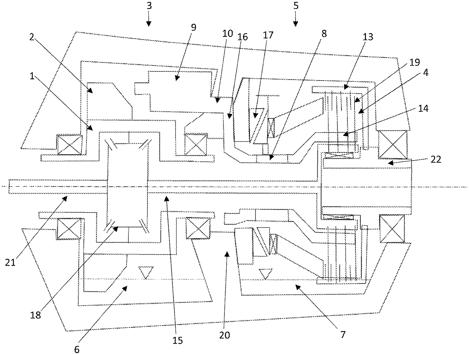
[0028] FIG. 1 is a sectional view of a transfer gearbox device according to the invention with the clutch closed and the valve open, showing especially the oil feed (first oil guide).
[0029] FIG. 2 is a sectional view of a transfer gearbox device according to the invention with the clutch closed and the valve closed, showing especially the oil return (second oil guide) at a first time.
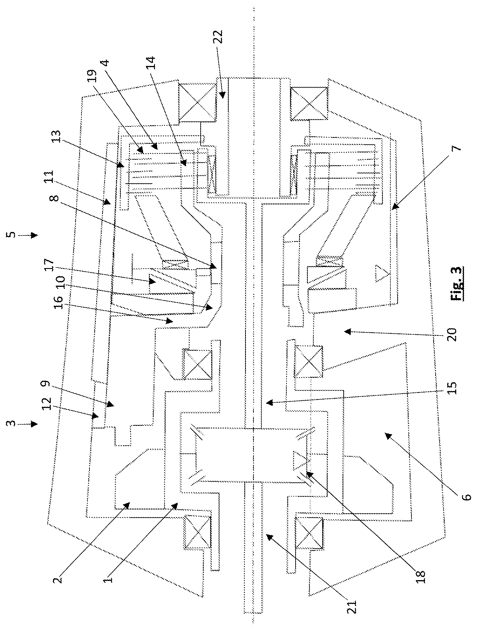
[0030] FIG. 3 is a sectional view of a transfer gearbox device according to the invention with the clutch open and the valve closed, showing especially the oil return (second oil guide) at a second time.
DESCRIPTION OF THE INVENTION
[0031] A transfer gearbox device according to the invention is illustrated in FIGS. 1-3.
[0032] The transfer gearbox device comprises a differential gear 1, having at least one crown wheel 2, as an input element of the differential gear 1, and having a first output shaft 15 and a second output shaft 21 on the two sides of the differential gear 1. The differential gear 1 is arranged in a first oil chamber 3 of the transfer gearbox device, and a friction clutch 4 is arranged in a second oil chamber 5 of the transfer gearbox device. By means of the friction clutch 4, the first output shaft 15 can be coupled to a clutch output shaft 22.
[0033] As can be seen in FIG. 1 (oil feed with the clutch 4 closed and the valve 8 open), the first oil chamber 3 comprises a first oil sump 6 and the second oil chamber 5 comprises a second oil sump 7 in the bottom region in the installed position. The oil level in the oil sumps is in each case indicated by a dotted line and a triangle resting by its tip on said line.
[0034] Arranged between the first oil chamber 3 and the second oil chamber 5 is a valve 8, and therefore, when the valve 8 is open, oil can pass via the valve 8 out of the first oil chamber 3 into the second oil chamber 5. The first and the second oil chamber 3, 5 are operated with a common oil quantity for the transfer gearbox device. When the valve 8 is closed, oil cannot pass via the valve 8 out of the first oil chamber 3 into the second oil chamber 5.
[0035] The valve 8 and the crown wheel 2 are arranged in such a manner that, when the valve 8 is open, upon rotation of the crown wheel 2 oil is conveyed by means of the crown wheel 2 out of the first oil sump 3 into a first oil collector 9 and is guided from the first oil collector 9 via a first oil guide 10, comprising an oil downpipe 16 and an oil finger 14, and via the open valve 8 radially inward to the friction clutch 4 in order to cool and/or to lubricate the friction clutch 4.
[0036] As can be seen in FIGS. 2 and 3, a second oil collector 11 and a second oil guide 12 of the transfer gearbox device are arranged in such a manner that, upon rotation of a component of the friction clutch 4, in particular a clutch cage 13 of the friction clutch 4 and/or plates 19 of the friction clutch 4, oil is conveyed by means of the component of the friction clutch 4, i.e. by means of clutch cage 13 and/or plates 19, out of the friction clutch 4 into the second oil collector 11 and is guided from the second oil collector 11 via the second oil guide 12 into the first oil sump 3.
[0037] In the connect state (closed clutch, FIGS. 1 and 2), the crown wheel 2 thus rotates and picks up oil from the first oil sump 3 and flings this oil at a high level into the first oil collector 9. The oil subsequently runs in the direction of an intermediate wall 20, which is positioned between the left-hand and the right-hand oil chamber and which therefore separates the first oil chamber 3 (drive assembly oil chamber), illustrated on the left, and the second oil chamber 5 (clutch oil chamber), illustrated on the right.
[0038] The intermediate wall 20 also serves as a bearing receptacle of the differential cage of the differential gear 1. Via the oil downpipe 16, the oil reaches the positions of actuation of the ball ramp, i.e. the clutch actuator 17. The valve 8 which can close and open the oil flow between the oil downpipe 16 and the oil finger 14 in a controlled manner is also implemented on this actuating mechanism, clutch actuator 17.
[0039] In the connect state (clutch closed, FIGS. 1 and 2), the valve 8 is open in a normal operating state (FIG. 1), with the result that the oil flows onward in the direction of the rotating oil finger 14. The oil is supplied radially on the inside to the clutch pack of the friction clutch 4 and flung off outward.
[0040] The oil flung off drips into the second oil sump 7 of the second oil chamber 5 and, once there, is immediately conveyed upward out of an oil pan by the pumping action of the clutch cage 13 and at that location is flung into an oil catching device, namely the second oil collector 11 (see FIG. 2).
[0041] From this oil catching device, the second oil collector 11, the oil can then flow back into the first oil chamber 3 (drive assembly oil chamber) with the second oil guide 12 as an oil return. This oil return via the second oil guide 12 can take place even when the valve 8 is closed (see FIG. 2), and this can take place, in particular, immediately before the opening of the friction clutch 4.
[0042] In the disconnect state (clutch open, FIG. 3), the valve 8 is closed and the feed to the second oil chamber 5 is thus blocked. The remaining oil present in the second oil chamber 5 is pumped off through the rotating clutch cage 13 by means of oil return to the left.
[0043] Thus, the first oil sump 6 in the left-hand, first oil chamber 3 is increased, and the tips of the side wheels 18 of the differential gear 1 dip into the sump in order in this way to ensure adequate lubrication of the differential. The crown wheel 2 can be stationary in this state.
[0044] The second oil sump 7 in the right-hand, second oil chamber 5 is reduced to a minimum, and the second oil chamber 5 becomes "virtually dry".
[0045] The size of the first oil chamber 3 can also be adapted, in particular the volumetric capacity thereof can be increased, in such a manner that, although the differential gear 1 receives sufficient oil for "torque idling", only slight drag torques are caused.
LIST OF REFERENCE SIGNS
[0046] 1 differential gear [0047] 2 crown wheel [0048] 3 first oil chamber [0049] 4 friction clutch [0050] 5 second oil chamber [0051] 6 first oil sump [0052] 7 second oil sump 8 valve [0053] 9 first oil collector [0054] 10 first oil guide [0055] 11 second oil collector [0056] 12 second oil guide [0057] 13 clutch cage [0058] 14 oil finger [0059] 15 first output shaft [0060] 16 oil downpipe [0061] 17 clutch actuator [0062] 18 side wheel [0063] 19 plates [0064] 20 intermediate wall [0065] 21 second output shaft [0066] 22 clutch output shaft
* * * * *
D00000
D00001
D00002
D00003
XML
uspto.report is an independent third-party trademark research tool that is not affiliated, endorsed, or sponsored by the United States Patent and Trademark Office (USPTO) or any other governmental organization. The information provided by uspto.report is based on publicly available data at the time of writing and is intended for informational purposes only.
While we strive to provide accurate and up-to-date information, we do not guarantee the accuracy, completeness, reliability, or suitability of the information displayed on this site. The use of this site is at your own risk. Any reliance you place on such information is therefore strictly at your own risk.
All official trademark data, including owner information, should be verified by visiting the official USPTO website at www.uspto.gov. This site is not intended to replace professional legal advice and should not be used as a substitute for consulting with a legal professional who is knowledgeable about trademark law.