Coating Installation And Corresponding Coating Method
Fritz; Hans-Georg ; et al.
U.S. patent application number 16/468694 was filed with the patent office on 2020-03-12 for coating installation and corresponding coating method. The applicant listed for this patent is Durr Systems AG. Invention is credited to Timo Beyl, Moritz Bubek, Hans-Georg Fritz, Frank Herre, Marcus Kleiner, Steffen Sotzny, Benjamin Wohr.
| Application Number | 20200078814 16/468694 |
| Document ID | / |
| Family ID | 60515409 |
| Filed Date | 2020-03-12 |


View All Diagrams
| United States Patent Application | 20200078814 |
| Kind Code | A1 |
| Fritz; Hans-Georg ; et al. | March 12, 2020 |
COATING INSTALLATION AND CORRESPONDING COATING METHOD
Abstract
The disclosure relates to a painting installation for painting components with a paint, in particular for painting motor vehicle body components, with a paint booth and an application device, in particular a print head, arranged in the paint booth, for applying the paint to the component located inside the paint booth, the application device operating essentially without overspray, so that the paint applied by the application device essentially completely on the component to be coated without overspray deposits. The disclosure provides that no paint separation is arranged below the first paint booth.
| Inventors: | Fritz; Hans-Georg; (Ostfildern, DE) ; Wohr; Benjamin; (Eibensbach, DE) ; Kleiner; Marcus; (Besigheim, DE) ; Bubek; Moritz; (Ludwigsburg, DE) ; Beyl; Timo; (Besigheim, DE) ; Herre; Frank; (Oberriexingen, DE) ; Sotzny; Steffen; (Oberstenfeld, DE) | ||||||||||
| Applicant: |
|
||||||||||
|---|---|---|---|---|---|---|---|---|---|---|---|
| Family ID: | 60515409 | ||||||||||
| Appl. No.: | 16/468694 | ||||||||||
| Filed: | December 1, 2017 | ||||||||||
| PCT Filed: | December 1, 2017 | ||||||||||
| PCT NO: | PCT/EP2017/081105 | ||||||||||
| 371 Date: | June 12, 2019 |
| Current U.S. Class: | 1/1 |
| Current CPC Class: | B05B 16/00 20180201; B05B 1/14 20130101; B05D 1/26 20130101; B05D 1/36 20130101; B05B 13/0452 20130101; B05D 1/02 20130101; B05B 13/0431 20130101; B05D 7/14 20130101; B05D 7/577 20130101 |
| International Class: | B05B 13/04 20060101 B05B013/04; B05D 7/14 20060101 B05D007/14 |
Foreign Application Data
| Date | Code | Application Number |
|---|---|---|
| Dec 14, 2016 | DE | 10 2016 014 953.1 |
Claims
1.-18. (canceled)
19. Painting installation for painting components with a paint, with a) at least one first paint booth, b) an application device arranged in the first paint booth for applying the paint to the component located inside the paint booth, the application device operating essentially without overspray, so that the paint applied by the application device deposits essentially completely on the component to be coated without overspray, c) wherein no paint separation is arranged below the first paint booth.
20. Painting installation according to claim 19, wherein a) the painting installation additionally has at least one second paint booth with at least one overspray-generating atomizer as application device, b) the first paint booth with the overspray-free application device is preferably designed for coating outer surfaces of the components to be coated, c) the second paint booth with the overspray-generating atomizer is designed for coating inner surfaces of the components to be coated.
21. Painting installation according to claim 20, wherein the first paint booth is arranged laterally next to the second paint booth.
22. Painting installation according to claim 19, wherein a) the painting installation has a floor foundation at floor level, the paint booth without the paint separation being arranged essentially at the floor level, and b) the first paint booth is arranged directly on the floor foundation, without a floor construction which raises the paint booth above the floor height, and c) the painting installation has a conveyor which conveys the components to be painted along a conveying path through the first paint booth, the conveyor being arranged at floor level, and d) the conveyor extends at floor level over the entire length of the painting installation.
23. Painting installation according to claim 19, further comprising a) a floor structure with a lower mounting level and an upper mounting level, b) a painting line running on the upper mounting level of the floor structure, c) a discharge for discharging the components to be painted from the raised painting line at the upper mounting level into the first paint booth at the floor level, and d) an infeed for infeeding the components to be painted from the first paint booth at the floor level into the raised painting line on the upper mounting level.
24. Painting installation according to claim 19, wherein a) the painting installation has a painting line with a plurality of successive painting stations, b) the components to be painted are conveyed by a conveyor along the painting line through the painting stations and are coated in the painting stations.
25. Painting installation according to claim 24, wherein a) the first paint booth without a paint separation is arranged outside the painting line, b) the components to be painted are discharged from the painting line by discharge means into the first paint booth without the paint separation means, and c) the components to be painted are introduced from the first paint booth without a paint separation into the painting line.
26. Painting installation according to claim 24, wherein the first paint booth without a paint separation is arranged in the painting line.
27. Painting installation according to claim 19, wherein a) external surfaces of the components to be painted are painted with the overspray-free application device, b) inner surfaces of the components to be painted are painted with an atomizer which applies a spray mist of the paint, and c) wraps around component edges of the components to be painted are painted with an atomizer which applies a spray mist of the paint.
28. Painting installation according to claim 27, wherein a) inner surfaces of the components to be painted are painted in an interior paint booth, b) outer surfaces of the components to be painted are painted in an exterior paint booth, and c) the wraps around the component edges of the components to be painted are painted in the interior paint booth or in the exterior paint booth.
29. Painting installation according to claim 19, wherein a) the painting line has a specific first cycle time with which the components to be painted are coated, and b) the first paint booth without the separation has a specific second cycle time with which the components to be painted are coated, and
30. Painting installation according to claim 29, wherein the second cycle time is at least 10% greater than the first cycle time.
31. Painting installation according to claim 29, wherein the second cycle time is equal to the first cycle time.
32. Painting installation according to claim 19, wherein a) in the first paint booth without the paint separation only rare special paintwork is painted, whereas frequent standard paintwork is painted in the painting line, and b) at least one of primer, adhesion promoter and seam sealings is applied in the first paint booth without the paint separation.
33. Painting installation according to claim 19, further comprising the following stations which are arranged one behind the other along a painting line so that the components to be painted are conveyed successively through the stations: a) a first filler station for the application of a filler layer in the interior of the component and at the wrap-around around component edges, wherein the application in the first filler station is effected by means of an atomizer which delivers a spray jet of the filler, b) a second filler station for applying a filler layer to the outer surface of the component, the application in the second filler station being effected by means of an overspray-free applicator, c) a first drying station for drying the filler layer on the component, d) a first base coat station for applying a first base coat layer to the inner surface of the component to be painted and at the wrap-around around component edges, the application in the first base coat station being effected by means of an atomizer which emits a spray jet, e) a second base coat station for applying the first base coat layer to the outer surface of the component to be coated, the application in the second base coat station being effected by means of an overspray-free applicator, f) a third base coat station for applying a second base coat layer to the outer surface of the component to be coated, the application in the third base coat station being effected by means of an overspray-free applicator or by means of an atomizer, g) a second drying station for intermediate drying of the first base coat layer and the second base coat layer, h) a first clear coat station for applying a clear coat layer in the interior of the component and at the wrap-around around component edges, the application in the first clear coat station being effected by means of an atomizer which delivers a spray jet of the clear coat, i) a second clear coat station for applying a clear coat layer to the outer surface of the component to be coated, the application in the second clear coat station being effected by means of an overspray-free applicator, and j) a third drying station for drying the clear coat.
34. Painting installation according to claim 19, further comprising the following stations which are arranged one behind the other along a painting line so that the components to be painted are conveyed successively through the stations: a) optionally a pre-coat station for applying a pre-coat layer to the component, the application in the second base coat station being effected by means of an overspray-free applicator, b) a first drying station for drying or evaporating the component, c) a first base coat station for applying a first base coat layer to the inner surface of the component to be coated and at the wrap-around around component edges, the application in the first base coat station being effected by means of an atomizer which emits a spray jet, d) a second base coat station for applying the first base coat layer to the outer surface of the component to be coated, the application in the second base coat station being effected by means of an overspray-free applicator, e) a third base coat station for applying a second base coat layer to the outer surface of the component to be coated, the application in the third base coat station being effected by means of an overspray-free applicator or by means of an atomizer, f) a second drying station for intermediate drying of the first base coat layer and the second base coat layer, g) a first clear coat station for applying a clear coat layer in the interior of the component and at the wrap-around around component edges, the application in the first clear coat station being effected by means of an atomizer which delivers a spray jet of the clear coat, h) a second clear coat station for applying a clear coat layer to the outer surface of the component to be coated, the application in the second clear coat station taking place by means of an overspray-free applicator, and i) a third drying station for drying the clear coat.
35. Painting installation according to claim 19, further comprising the following stations which are arranged one behind the other along a painting line so that the components to be painted are conveyed successively through the stations: a) a first filler station for the application of a filler layer in the interior of the component and at the wrap-around around component edges, wherein the application in the first filler station is effected by means of an atomizer which delivers a spray jet of the filler, b) a second filler station for applying a filler layer to the outer surface of the component, the application in the second filler station being effected by means of an overspray-free applicator, c) a first base coat station for applying a first base coat layer to the inner surface of the component to be coated and at the wrap-around around component edges, the application in the first base coat station being effected by means of an atomizer which emits a spray jet, d) a second base coat station for applying the first base coat layer to the outer surface of the component to be coated, the application in the second base coat station being effected by means of an overspray-free applicator, e) a third base coat station for applying a second base coat layer to the outer surface of the component to be coated, the application in the third base coat station being effected by means of an overspray-free applicator or by means of an atomizer, f) optionally a first drying station for intermediate drying of the first base coat layer and the second base coat layer, g) a first clear coat station for applying a clear coat layer in the interior of the component and at the wrap-around around component edges, the application in the first clear coat station being effected by means of an atomizer which delivers a spray jet of the clear coat, h) a second clear coatstation for applying a clear coat layer to the outer surface of the component to be coated, the application in the second clear coatstation being effected by means of an overspray-free applicator, and i) a second drying station for drying the clear coat layer.
36. Painting installation according to claim 19, further comprising a primerless painting process without a primer with the following process steps in the following order: a) Application of a first base coat layer instead of the filler, b) Optional application of a second base coat layer as top coat and optional metallic effect, c) Optional application of a metallic paint layer, d) application of a clear coat layer.
37. Painting installation conforming to claim 19, further comprising a primerless painting process without a primer with the following process steps in the following order: a) Application of a precoat with a filler function, b) Application of a first base coat layer as top coat, c) Application of a second base coat layer as top coat, d) application of a layer of clear coat layer.
38. Painting installation according to claim 19, further comprising the following process steps: a) application of a paint having at least one base coat layer and optionally a clear coat layer to the component to be painted by means of an atomizer which applies a spray mist of the paint, and b) applying a decoration to the component to be painted by an overspray-free application device, and c) optional application of a clear coat layer.
Description
CROSS-REFERENCE TO RELATED APPLICATIONS
[0001] This application is a national stage of, and claims priority to, Patent Cooperation Treaty Application No. PCT/EP2017/081105, filed on Dec. 1, 2017, which application claims priority to German Application No. DE 10 2016 014 953.1, filed on Dec. 14, 2016, which applications are hereby incorporated herein by reference in their entireties.
BACKGROUND
[0002] The disclosure concerns a painting installation for the painting of components with a paint, in particular for the painting of car body components. Furthermore, the disclosure concerns a corresponding painting process.
[0003] In modern painting installations for the painting of car body components, atomizers (e.g. rotary atomizers, air atomizers, airmix atomizers, airless atomizers, etc.) are usually used as application devices, which emit a spray of the paint to be applied. A disadvantage of these well-known atomizers is the fact that only part of the applied paint deposits on the surface of the vehicle body components to be coated, while the rest of the applied paint has to be disposed of as so-called overspray or is deposited on other areas of the component to be coated where no paint is to be deposited. For this purpose, a so-called paint separation system is located under the actual paint booth, which removes the unwanted overspray from the downward flowing booth air.
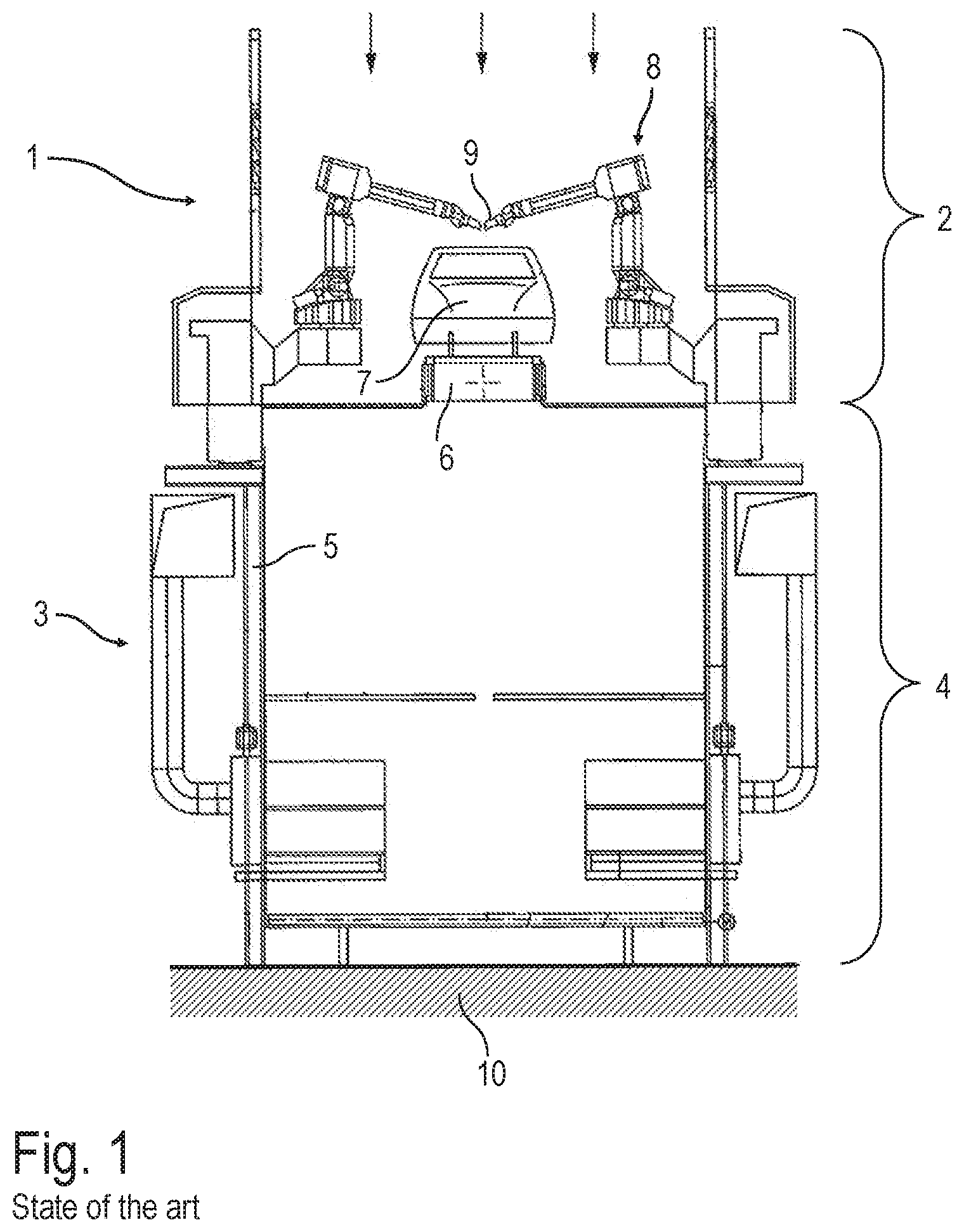
[0004] FIG. 1 shows a schematic cross-sectional view through a conventional painting installation with a paint booth 1 on an upper floor 2 and a paint separation 3 on a lower floor 4. The construction of the painting installation with the two floors 2, 4 one above the other requires a steel construction 5 or alternatively a concrete ceiling with a cut-out to lift the paint booth above the level of the paint separation 3, so that the air flowing downwards from the paint booth 1 can enter the paint separation 3 through the grid floor, as schematically indicated by the arrows. In paint booth 1, a conveyor 6 runs at right angles to the drawing plane, with the conveyor 6 conveying the vehicle body components to be painted through the painting installation at right angles to the drawing plane. Multi-axis painting robots 8 are arranged on both sides of the conveyor 6, each of which guides a rotary atomizer 9 as an application device. An example of the design and construction of the paint separation 3 is described in DE 20 2006 021 158 U1. It should also be mentioned that the steel structure 5 rests on a concrete foundation 10.
[0005] A main disadvantage of this well-known structure of a painting installation is the fact that paint separation 3 is necessary at all, since the paint separation 3 requires water, chemicals, stone flour and/or cardboard filters.
[0006] Another disadvantage of this well-known structure of a painting installation is the fact that the steel structure 5 is required to support the paint booth 1 and to position it above paint separation 3.
[0007] With regard to the technical background of the disclosure, reference is also made to DE 10 2010 019 612 A1, DE 197 31 829 A1, DE 602 12 523 T2, DE 94 22 327 U1, DE 10 2013 002 412 A1, DE 196 30 290 A1, DE 41 15 111 A1 and DE 196 06 716 C1.
BRIEF DESCRIPTION OF THE DRAWINGS
[0008] FIG. 1 a cross-sectional view through a conventional painting installation with a paint separation under the paint booth,
[0009] FIG. 2A a cross-sectional view through a paint booth according to the disclosure,
[0010] FIG. 2B a modification of FIG. 2A,
[0011] FIG. 2C a modification of FIG. 2A,
[0012] FIG. 3 shows an example of a painting method according to the disclosure in the form of a flow chart,
[0013] FIG. 4 a modification of FIG. 3,
[0014] FIG. 5 a modification of FIG. 3 with a 3-wet process,
[0015] FIG. 6 another modification of a painting process according to the disclosure,
[0016] FIG. 7 a modification of FIG. 6,
[0017] FIG. 8 another modification, and
[0018] FIG. 9 a schematic illustration of the painting of wrap-arounds around component edges.
DETAILED DESCRIPTION
[0019] The disclosure is therefore based on the task of creating a correspondingly improved painting installation and a corresponding painting method.
[0020] The painting installation according to the disclosure first has at least one first paint booth in which the components to be painted are painted by an application device. Here, however, a rotary atomizer is not used as the application device--as in the conventional structure of a painting installation described at the beginning and shown in FIG. 1--but rather a print head which essentially works without overspray, so that the paint applied by the application device is deposited essentially completely on the component to be coated without overspray.
[0021] Such printheads are known from the state of the art and are described for example in DE 10 2013 002 412 A1, U.S. Pat. No. 9,108,424 B2 and DE 10 2010 019 612 A1. However, the term "printhead" used in the disclosure is to be understood generally and is not limited to the specific printheads described in the above publications. Rather, the term "print head" used in the context of the disclosure merely serves to distinguish between atomizers that emit a spray of the paint to be applied. In contrast, a print head according to the disclosure emits a spatially narrowly limited jet of coating medium, which can be formed either as a droplet jet or as a jet of coating medium, which is continuous in the longitudinal direction of the jet.
[0022] For the first time, the disclosure provides for the elimination of the time-consuming separation of paint under the first paint booth. However, the disclosure does not only claim protection for painting installations where all paint booths are designed without an associated paint separation. Rather, the disclosure also claims protection for a painting installation with several paint booths, whereby at least one of the paint booths works with an overspray-free print head as an application device and therefore has no associated paint separation, while the other paint booths can rather use conventional atomizers (e.g. rotary atomizers) as an application device.
[0023] The combination of overspray-free print heads with overspray-generating atomizers in a painting line is advantageous because, for example, so-called wrap-around component edges are difficult to paint with the currently known print heads. It therefore makes sense to continue painting these areas (e.g. wrap-around component edges) with conventional atomizers (e.g. rotary atomizers). The wrap-around creates the layer of paint produced during electrostatic painting, which is deposited in the effective area of the field lines, which could not be coated without the effect of the field lines.
[0024] The overspray-free print heads, on the other hand, are preferably used for painting the outer surfaces of the components to be painted, while the overspray-generating atomizers can be used for painting the inner surfaces of the components to be painted or for painting the above-mentioned wrap-arounds at the edges of the components.
[0025] In the painting installation according to the disclosure, the first paint booth with the overspray-free print heads can be arranged at floor level without the steel construction described above, especially directly on a floor foundation. The renunciation of a paint separation thus also allows the combination of overspray-free print heads with overspray-generating atomizers in a painting line to dispense with the steel construction described above and thus enables the arrangement of the at least one overspray-free paint booth directly on a floor foundation which is arranged at the level of the grating of the paint booth with overspray separation. Accordingly, the conveyor for conveying the components to be painted can also be arranged at floor level and, in particular, directly on the floor foundation, which is also advantageous.
[0026] It should be mentioned here that the conveyor can run at floor level over the entire length of the painting installation.
[0027] Alternatively, it is also possible that the first paint booth with the overspray-free print heads as application device is arranged at floor level, whereas the other paint booths with the atomizers as application device are arranged in the conventional way above a paint separation. In this case, the components to be painted must be lowered or raised as they pass through the painting line. The painting line can run on an upper assembly level, as is known from the state of the art. If the paint booth with the overspray-free print heads is now arranged at floor level, the components to be painted must be discharged from the upper paint line to the bottom and then returned to the top, which can be done using a lift, for example.
[0028] Alternatively, it is also possible for the paint booth with the overspray-free print heads to be located to the side of the actual main painting line, which, however, also requires the components to be painted to be introduced or discharged again.
[0029] In one example, the painting installation has an interior paint booth and an exterior paint booth, which are arranged one behind the other along the painting line and through which the components to be painted pass one after the other. In the interior paint booth, the inner surfaces of the components to be painted are painted. In the exterior paint booth, on the other hand, the exterior surfaces of the components to be painted are painted. The aforementioned wrap-around component edges are then painted either in the interior paint booth or in the exterior paint booth, so that these paint booths have an extended painting scope.
[0030] It should also be mentioned that the painting line preferably has a certain cycle time with which the components to be painted are coated. The cycle time of the paint booth with the overspray-free print heads is then preferably longer than the cycle time of the main painting line, for example by 10%, 20%, 50%, 100%, 200%, 300% or 500%. Alternatively, it is also possible that the cycle time of the paint booth with the overspray-free print heads is equal to or less than the cycle time of the main spray line.
[0031] In a preferred example of the disclosure, in the paint booth with overspray-free print heads, i.e. without paint separation, only rare special paints or decorative paints are applied, whereas frequent standard paints are painted with atomizers in the general painting line. In addition, primers, adhesion promoters or seam sealing (NAD: Nahtabdichtung) can also be applied in the paint booth with the overspray-free print heads.
[0032] In one example, the painting installation has the following painting stations (e.g. paint booths) which are arranged one behind the other along a painting line so that the components to be painted are conveyed through the stations one after the other in a filling process:
[0033] A first filler station for the application of a filler layer in the interior of the component and at the wrap around component edges, whereby the application in the first filler station takes place using an atomizer (e.g. rotary atomizer) and the wrap also extends to outer surfaces.
[0034] A second filler station for applying a filler layer to the outer surface of the component, the application in the second filler station using an overspray-free applicator, in particular with a print head.
[0035] A first drying station for drying the filler layer on the component.
[0036] A first base coat station for applying a first base coat layer to the inner surface of the component to be coated and around the edges of the component at the wrap around, the application in the first base coat station using an atomizer which emits a spray jet and the wrap-around also extends to outer surfaces.
[0037] A second base coat station for applying the first base coat layer to the outer surface of the component to be coated, the application being carried out in the second base coat layer with an overspray-free applicator.
[0038] A third base coat station for applying a second base coat layer to the outer surface of the component to be painted, the application being carried out in the third base coat station by an overspray-free applicator or by an atomizer.
[0039] A second drying station for intermediate drying of the first base coat layer and the second base coat layer.
[0040] A first clear coat station for the application of a clear coat layer in the interior of the component and at the wrap-around component edges, the application in the first clear coat station being carried out by an atomizer which emits a spray mist of the clear coat and the wrap-around also extends to outer surfaces.
[0041] A second clear coat station for applying a clear coat layer to the outer surface of the component to be coated, the application being carried out in the second clear coat station by an overspray-free applicator, in particular by a print head.
[0042] A third drying station for drying the clear coat layer.
[0043] In another example, a fillerless process is used. Instead of the filler application described above, in the first two stations a precoat or a so-called BC0=BC zero (a base coat applied before the actual first base coat, which can be done using an overspray-free print head) is optionally used.
[0044] In a further example, a so-called "3-wet process" is provided. A filler is optionally applied in a first station, which can be done by means of a conventional atomizer. It should be mentioned here that a wrap-around is required for all paint layers. The remaining steps then correspond to the steps described above with the exception of the 3-wet process.
[0045] In a variant of the disclosure, it is provided to first apply a first base coat layer instead of the filler. A second base coat can then optionally be applied as a top coat and optionally with a metallic effect. Finally, a clear coat can be applied. This, too, is preferably a primerless coating process.
[0046] The following process steps are provided in a further example of a fillerless painting process:
[0047] Application of a precoat with a filler function,
[0048] Application of a first base coat as top coat,
[0049] Application of a second base coat as top coat,
[0050] Application of a clear coat.
[0051] Furthermore, the painting installation according to the disclosure is very suitable for decorative painting. A base coat can first be applied to the component to be painted, which can be done using a conventional atomizer. The desired decor (e.g. graphic) can then be applied to the component using an overspray-free application device. The decor is then protected with a clear coat layer.
[0052] Furthermore, the paint booth without paint separation comprises an air duct with a supply air duct and an exhaust air duct. The supply air duct can be realised as a supply air ceiling, while the exhaust air ducting can be designed as an exhaust air floor. Alternatively, the exhaust air duct can have exhaust air ducts on the floor, e.g. next to the body, under the body or on the cabin wall. However, the supply air could also come from ducts on the ceiling. The supply and exhaust air is also necessary without paint separation, as paint is still being applied to the car. For example, the solvents still have to be removed and the paint has to evaporate.
[0053] With reference to the figures, FIG. 2A shows a cross-sectional view of a paint booth 1 according to the disclosure, partially identical with the conventional paint booth 1 shown in FIG. 1, so that reference is made to the above description to avoid repetition, using the same reference marks for corresponding details.
[0054] A feature of this design example is that print heads 11, which are guided by the painting robots 8, are used as the application device instead of the rotary atomizers 9. The print heads 11, however, do not emit a spray of the paint to be applied, but a narrowly confined jet of coating agent and are therefore essentially free of overspray. This offers the advantage that the paint separation 3 can be dispensed with. Rather, there is only one exhaust air duct 12 below the paint booth 1, through which the downward air flow in the paint booth 1 can be discharged.
[0055] This renunciation of the paint separation 3, which is possible according to the disclosure, again makes it possible to dispense with the steel construction 5, so that the paint booth 1 can be mounted almost at floor level.
[0056] FIG. 2B shows another modification, so that to avoid repetitions, reference is made again to the above description, using the same reference symbols for corresponding details.
[0057] A special feature of this example is that the conveyor 6 for conveying the motor vehicle body components 7 is arranged directly on the concrete foundation 10'.
[0058] The painting installation according to the disclosure therefore only has to have a single floor, since no separate floor is required for the paint separation 3. This in turn allows the painting installation to be installed in relatively low halls. However, this only applies if overspray-free application equipment is used exclusively.
[0059] FIG. 2C shows a further modification so that the above description is referred to again in order to avoid repetitions, whereby the same reference symbols are used for corresponding details.
[0060] FIG. 2C, for example, shows a modification according to the disclosure in which an overspray-free paint booth 1' is connected to the paint booth 1 with the paint separation 3 (overspray separation). The concrete foundation 10' of the overspray-free paint booth 1' is arranged at the same height as the grating of the paint booth 1 with the paint separation 3 (overspray separation).
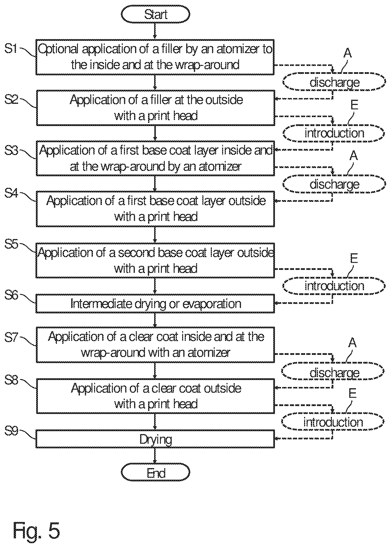
[0061] FIG. 3 shows a flow chart to illustrate an example of a painting process according to the disclosure with a filler.
[0062] In a first step, S1, a filler is applied in the conventional way by means of a atomizer to the inner surfaces of the vehicle body components to be painted and around the edges of the component.
[0063] In a further step, S2, a filler is then applied to the outer surfaces of the vehicle body components to be painted using an overspray-free print head.
[0064] In the next step, S3, the vehicle body components are then dried.
[0065] A step S4 then provides for a first base coat layer to be applied to the inner surfaces of the vehicle body components and around the edges of the component by means of an atomizer.
[0066] In a further step, S5, a first base coat layer is applied to the outer surfaces of the vehicle body components using an overspray-free print head.
[0067] Step S6 then involves applying a second base coat layer to the outer surfaces of the vehicle body component using an overspray-free print head.
[0068] In a step S7, the vehicle body components are then dried.
[0069] A step S8 then provides for a clear coat to be applied to the inner surfaces and around the edges of the component by an atomizer.
[0070] In a further step, S9, a clear coat is then applied to the outer surfaces of the vehicle body components using an overspray-free print head.
[0071] In one step S10, the vehicle body components are then finally dried.
[0072] In a modification of this example, the entire painting line runs through all the painting cabins on an upper floor, so that there is no difference in height between the painting cabins with the atomizers and the painting cabins with the overspray-free print heads. The paint booths with the overspray-free print heads can then also have a steel or concrete construction so that these paint booths are at the same height level as the other paint booths with the overspray-generating atomizers. The paint booths with the overspray-free print heads can also be installed on solid false ceilings and/or without recesses or basements.
[0073] In another modification of the disclosure, the paint booths with the overspray-free print heads are lowered, since they do not require paint separation. In this case, it is necessary to overcome the difference in height, which is done by means of a discharge A or an infeed E. This discharge A or the infeed E from the elevated painting line or into the elevated painting line can be carried out, for example, by means of a lift.
[0074] FIG. 4 shows a modification of the example according to FIG. 3, so that to avoid repetitions, reference is made to the above description, using the same reference signs for corresponding details.
[0075] A feature of this example is that it is a primerless painting process. In step S1, therefore, no filler is applied, but a precoat or a BC0, which can be done using a print head. Furthermore, in step S2, either evaporation or intermediate drying takes place.
[0076] Otherwise, this painting process essentially corresponds to the painting process described above and shown in FIG. 3.
[0077] FIG. 5 shows a further modification, which in turn partially corresponds to the examples given in FIGS. 3 and 4, so that reference is made to the above description in order to avoid repetitions, whereby the same reference signs are used for corresponding details.
[0078] A feature of this example is that it is a so-called 3-wet process. In the first step, a filler is optionally applied inside and on the wrap-around by means of a atomizer.
[0079] In the second step, S2, a filler is then applied to the outer surfaces of the vehicle body components, which can be done using an overspray-free print head.
[0080] The further procedural steps again essentially correspond to the procedural steps described above, so that reference is made to the above description in this regard.
[0081] FIG. 6 shows another simple example. In the first step S1, a first base coat layer is applied instead of a filler, i.e. the base coat layer also has a filler function. In a second step, S2, a second base coat layer is applied, which can also have a metallic effect. Finally, a clear coat layer is applied in step S3.
[0082] FIG. 7 shows another example of a coating process based on the disclosure. In a first step S1, a precoat with a filler function is applied. A first base coat layer is then applied in step S2 and a second base coat layer in step S3. Finally, a clear coat layer is applied in step S4.
[0083] In the example shown in FIG. 8, a conventional paint structure with filler and base coat is first applied using an atomizer. In one step S2, a decor is then applied, which can be done using an overspray-free print head. Then a clear coat layer is applied.
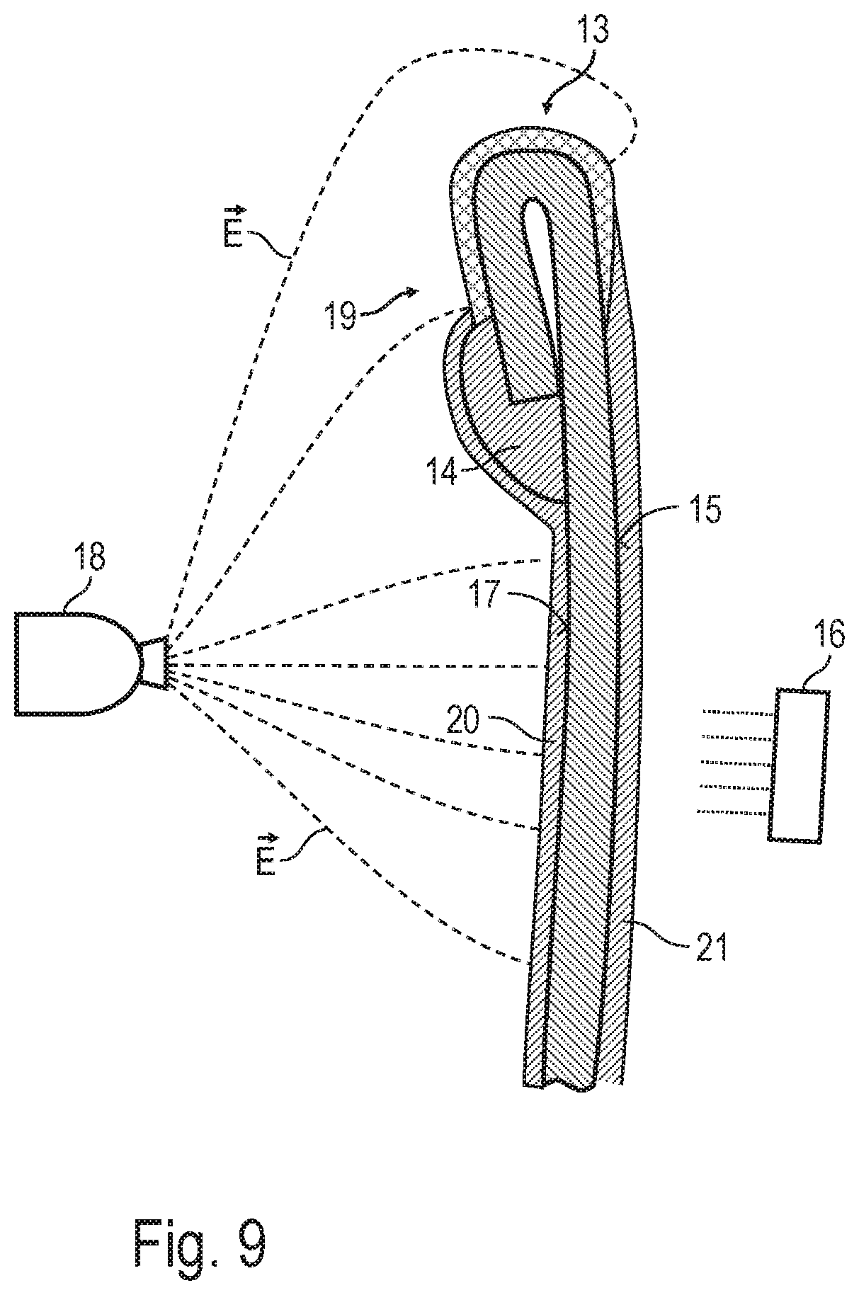
[0084] FIG. 9 shows a simplified and schematic cross-sectional view through a component edge 13 of a component, such as a car body component. The component edge 30 is flanged and sealed with a flange seam seal 14. The outer surfaces 15 of the motor vehicle body component are coated with a paint layer 21 by an overspray-free print head 16, while the inner surfaces 17 of the component are coated with a paint layer 20 by a conventional atomizer 18. In addition, the component edge 13 is coated with the paint layer 19, which is also applied by the atomizer 18, by the electrostatic wrap-around.
[0085] The coating of the wrap-around area and the component edge 13 with the atomizer 18 instead of the print head 16 is advantageous, since the coating of extremely strongly curved surfaces with a very small radius of curvature with the print heads 16 is so far only very badly possible.
[0086] The disclosure is not limited to the preferred examples described above. Rather, a large number of variants and modifications are possible which also make use of the idea of the disclosure and therefore fall within the scope of protection.
* * * * *
D00000
D00001
D00002
D00003
D00004
D00005
D00006
D00007
D00008
D00009
D00010
D00011
XML
uspto.report is an independent third-party trademark research tool that is not affiliated, endorsed, or sponsored by the United States Patent and Trademark Office (USPTO) or any other governmental organization. The information provided by uspto.report is based on publicly available data at the time of writing and is intended for informational purposes only.
While we strive to provide accurate and up-to-date information, we do not guarantee the accuracy, completeness, reliability, or suitability of the information displayed on this site. The use of this site is at your own risk. Any reliance you place on such information is therefore strictly at your own risk.
All official trademark data, including owner information, should be verified by visiting the official USPTO website at www.uspto.gov. This site is not intended to replace professional legal advice and should not be used as a substitute for consulting with a legal professional who is knowledgeable about trademark law.