Golf Ball
Watanabe; Hideo ; et al.
U.S. patent application number 16/540618 was filed with the patent office on 2020-03-12 for golf ball. This patent application is currently assigned to Bridgestone Sports Co., Ltd.. The applicant listed for this patent is Bridgestone Sports Co., Ltd.. Invention is credited to Katsunori Sato, Hideo Watanabe.
| Application Number | 20200078643 16/540618 |
| Document ID | / |
| Family ID | 69721079 |
| Filed Date | 2020-03-12 |

| United States Patent Application | 20200078643 |
| Kind Code | A1 |
| Watanabe; Hideo ; et al. | March 12, 2020 |
GOLF BALL
Abstract
A golf ball for amateur golfers is endowed with both an excellent flight and a good feel at impact that is soft and solid when hit by the average golfer whose head speed is not very high. The golf ball, which includes a core and a cover, has a compressive deformation A when subjected to a final load of 5 kg from an initial load of 0.2 kg that is 0.21 mm or less, a compressive deformation B when subjected to a final load of 30 kg from an initial load of 5 kg that is from 0.72 to 0.90 mm and a compressive deformation C when subjected to a final load of 60 kg from an initial load of 5 kg that is from 1.55 to 1.80 mm.
| Inventors: | Watanabe; Hideo; (Chichibushi, JP) ; Sato; Katsunori; (Chichibushi, JP) | ||||||||||
| Applicant: |
|
||||||||||
|---|---|---|---|---|---|---|---|---|---|---|---|
| Assignee: | Bridgestone Sports Co.,
Ltd. Tokyo JP |
||||||||||
| Family ID: | 69721079 | ||||||||||
| Appl. No.: | 16/540618 | ||||||||||
| Filed: | August 14, 2019 |
| Current U.S. Class: | 1/1 |
| Current CPC Class: | A63B 37/0031 20130101; A63B 37/0063 20130101; A63B 37/0068 20130101; A63B 37/0087 20130101; A63B 37/0076 20130101; A63B 37/0032 20130101; A63B 2037/0079 20130101; A63B 37/0043 20130101; A63B 37/0084 20130101; A63B 37/0044 20130101; A63B 37/0022 20130101; A63B 37/0062 20130101; A63B 37/0092 20130101 |
| International Class: | A63B 37/00 20060101 A63B037/00 |
Foreign Application Data
| Date | Code | Application Number |
|---|---|---|
| Sep 11, 2018 | JP | 2018-169572 |
Claims
1. A golf ball comprising a core and a cover, wherein the ball has an amount of compressive deformation such that the compressive deformation A when the ball is subjected to a final load of 5 kg from an initial load state of 0.2 kg is 0.21 mm or less, the compressive deformation B when the ball is subjected to a final load of 30 kg from an initial load state of 5 kg is from 0.72 to 0.90 mm and the compressive deformation C when the ball is subjected to a final load of 60 kg from an initial load state of 5 kg is from 1.55 to 1.80 mm.
2. The golf ball of claim 1, wherein the compressive deformation D when the ball is subjected to a final load of 130 kg from an initial load state of 10 kg is from 2.80 to 3.40 mm.
3. The golf ball of claim 2, wherein the ratio D/C between compressive deformation D and compressive deformation C is from 1.80 to 1.90.
4. The golf ball of claim 2, wherein the ratio D/B between compressive deformation D and compressive deformation B is from 3.65 to 4.20.
5. The golf ball of claim 2, wherein the ratio D/A between compressive deformation D and compressive deformation A is from 16.0 to 25.0.
6. The golf ball of claim 1, wherein the ball further comprises, between the core and the cover, at least an envelope layer and an intermediate layer, which golf ball has a construction of four or more layers that includes a core, an envelope layer, an intermediate layer and a cover.
7. The golf ball of claim 6 which satisfies the following surface hardness relationship: (1) Shore D hardness at surface of cover>Shore D hardness at surface of intermediate layer>Shore D hardness at surface of envelope layer>Shore D hardness at center of core.
8. The golf ball of claim 1 wherein, letting Cc be the Shore C hardness at a center of the core and Cs be the Shore C hardness at a surface of the core, the Shore D hardness difference between the surface and center of the core (Cs-Cc) is 20 or more.
9. The golf ball of claim 1, wherein the cover has a paint film layer formed on a surface thereof, which paint film layer has a material hardness that is higher than the core center hardness (Cc).
10. The golf ball of claim 6 which satisfies the following initial velocity relationships (2), (3) and (4): (2) -0.8 m/s.ltoreq.(ball initial velocity-core initial velocity).ltoreq.0 m/s, (3) -0.4 m/s.ltoreq.(ball initial velocity-initial velocity of intermediate layer-encased sphere).ltoreq.0.4 m/s, and (4) 0 m/s.ltoreq.(initial velocity of intermediate layer-encased sphere-initial velocity of envelope layer-encased sphere).ltoreq.0.4 m/s.
11. A golf ball comprising a core and a cover, wherein the ball has an amount of compressive deformation such that, letting A be the compressive deformation when the ball is subjected to a final load of 5 kg from an initial load state of 0.2 kg, B be the compressive deformation when the ball is subjected to a final load of 30 kg from an initial load state of 5 kg, C be the compressive deformation when the ball is subjected to a final load of 60 kg from an initial load state of 5 kg and D be the compressive deformation when the ball is subjected to a final load of 130 kg from an initial load state of 10 kg, D has a value of from 2.80 to 3.40 mm, the ratio D/C is from 1.80 to 1.90, the ratio D/B is from 3.65 to 4.20 and the ratio D/A is from 16.0 to 25.0.
Description
CROSS-REFERENCE TO RELATED APPLICATION
[0001] This non-provisional application claims priority under 35 U.S.C. .sctn. 119(a) on Patent Application No. 2018-169572 filed in Japan on Sep. 11, 2018, the entire contents of which are hereby incorporated by reference.
TECHNICAL FIELD
[0002] The present invention relates to a golf ball which has a core and a cover, and is intended for use by amateur golfers lacking a fast head speed.
BACKGROUND ART
[0003] In the field of golf balls for amateur golfers, numerous balls intended to satisfy amateur players in terms of flight performance and feel have hitherto been developed. For example, JP-A H08-280845 describes a golf ball wherein, using the amount of compressive deformation when a final load of 5 kg is applied from an initial load state of 0.2 kg as an indicator of the influence exerted on the ball properties when a small impact force has acted upon a golf ball, this value is set in the range of from 0.26 to 0.40 mm. However, this golf ball is a spin-type ball that is targeted primarily at the spin on approach shots, and does not fully satisfy the flight performance desired on shots with a driver.
[0004] In addition, a variety of functional, multi-piece solid golf balls in which the ball has a multilayer construction and the surface hardnesses of the respective layers--i.e., the core, envelope layer, intermediate layer and cover (outermost layer)--are optimized have been described. These include the multi-piece solid golf balls disclosed in JP-A 2014-132955, JP-A 2015-173860, JP-A 2016-16117 and JP-A 2016-179052. The golf balls disclosed in these patent publications satisfy the following hardness relationship: ball surface hardness>intermediate layer surface hardness>envelope layer surface hardness<core surface hardness, and impart an excellent flight performance even when used by amateur golfers lacking a fast head speed. However, these prior-art golf balls do not optimize the amount of compressive deformation when subjected to a final load of 5 kg from an initial load state of 0.2 kg and the amount of compressive deformation when subjected to a final load of 30 kg from an initial load state of 5 kg. That is, no attention has been paid to how the golf ball properties are affected by the magnitude of the impact force acting on the ball, and so there remains room for improvement in obtaining a good flight performance and a good feel at impact in golf ball products for amateur golfers.
SUMMARY OF THE INVENTION
[0005] It is therefore an object of the present invention to provide a golf ball for amateur golfers which has an excellent flight when hit by the average golfer whose head speed is not that high and which also has a good feel at impact that is both soft and solid.
[0006] As a result of extensive investigations, we have focused on the relationship, in golf balls having a core and a cover, between the magnitude of the force of impact applied to the golf ball and the ball characteristics of flight performance and feel. We have discovered in particular that, in the amount of compressive deformation by the golf ball, by specifying the following respective compressive deformations: the compressive deformation A when the ball is subjected to a final load of 5 kg from an initial load state of 0.2 kg, the compressive deformation B when the ball is subjected to a final load of 30 kg from an initial load state of 5 kg, the compressive deformation C when the ball is subjected to a final load of 60 kg from an initial load state of 5 kg and the compressive deformation D when the ball is subjected to a final load of 130 kg from an initial load state of 10 kg, as well as the ratios therebetween, a flight performance that is satisfactory when the ball is hit with all golf clubs, including drivers (W #1) and irons, can be fully obtained by golfers lacking a fast head speed, in addition to which a feel that is both soft and solid can be obtained.
[0007] Accordingly, in a first aspect, the invention provides a golf ball that includes a core and a cover, wherein the ball has an amount of compressive deformation such that the compressive deformation A when the ball is subjected to a final load of 5 kg from an initial load state of 0.2 kg is 0.21 mm or less, the compressive deformation B when the ball is subjected to a final load of 30 kg from an initial load state of 5 kg is from 0.72 to 0.90 mm, and the compressive deformation C when the ball is subjected to a final load of 60 kg from an initial load state of 5 kg is from 1.55 to 1.80 mm.
[0008] In a preferred embodiment of the golf ball of the invention, the compressive deformation D when the ball is subjected to a final load of 130 kg from an initial load state of 10 kg is from 2.80 to 3.40 mm.
[0009] In another preferred embodiment of the inventive golf ball, the ratio D/C between compressive deformation D and compressive deformation C is from 1.80 to 1.90.
[0010] In yet another preferred embodiment, the ratio D/B between compressive deformation D and compressive deformation B is from 3.65 to 4.20.
[0011] In still another preferred embodiment, the ratio D/A between compressive deformation D and compressive deformation A is from 16.0 to 25.0.
[0012] In a further preferred embodiment, the ball additionally includes, between the core and the cover, at least an envelope layer and an intermediate layer, thus having a construction of four or more layers that includes a core, an envelope layer, an intermediate layer and a cover.
[0013] In a still further preferred embodiment, the golf ball satisfies the following surface hardness relationship:
(1) Shore D hardness at surface of cover>Shore D hardness at surface of intermediate layer>Shore D hardness at surface of envelope layer>Shore D hardness at center of core.
[0014] In another preferred embodiment of the inventive golf ball, letting Cc be the Shore C hardness at a center of the core and Cs be the Shore C hardness at a surface of the core, the Shore C hardness difference between the surface and center of the core (Cs-Cc) is 20 or more.
[0015] In yet another preferred embodiment, the cover has a paint film layer formed on a surface thereof, which paint film layer has a material hardness that is higher than the core center hardness (Cc).
[0016] In still another preferred embodiment, the golf ball satisfies the following initial velocity relationships (2), (3) and (4):
(2) -0.8 m/s.ltoreq.(ball initial velocity-core initial velocity).ltoreq.0 m/s, (3) -0.4 m/s.ltoreq.(ball initial velocity-initial velocity of intermediate layer-encased sphere).ltoreq.0.4 m/s, and (4) 0 m/s.ltoreq.(initial velocity of intermediate layer-encased sphere-initial velocity of envelope layer-encased sphere).ltoreq.0.4 m/s.
[0017] In a second aspect, the invention provides a golf ball that includes a core and a cover, wherein the ball has an amount of compressive deformation such that, letting A be the compressive deformation when the ball is subjected to a final load of 5 kg from an initial load state of 0.2 kg, B be the compressive deformation when the ball is subjected to a final load of 30 kg from an initial load state of 5 kg, C be the compressive deformation when the ball is subjected to a final load of 60 kg from an initial load state of 5 kg and D be the compressive deformation when the ball is subjected to a final load of 130 kg from an initial load state of 10 kg, D has a value of from 2.80 to 3.40 mm, the ratio D/C is from 1.80 to 1.90, the ratio D/B is from 3.65 to 4.20 and the ratio D/A is from 16.0 to 25.0.
Advantageous Effects of the Invention
[0018] The golf ball of the invention has an excellent flight performance when hit by golfers whose head speeds are not that high and also has a good feel at impact that is both soft and solid, making it highly suitable for use by amateur golfers.
BRIEF DESCRIPTION OF THE DIAGRAMS
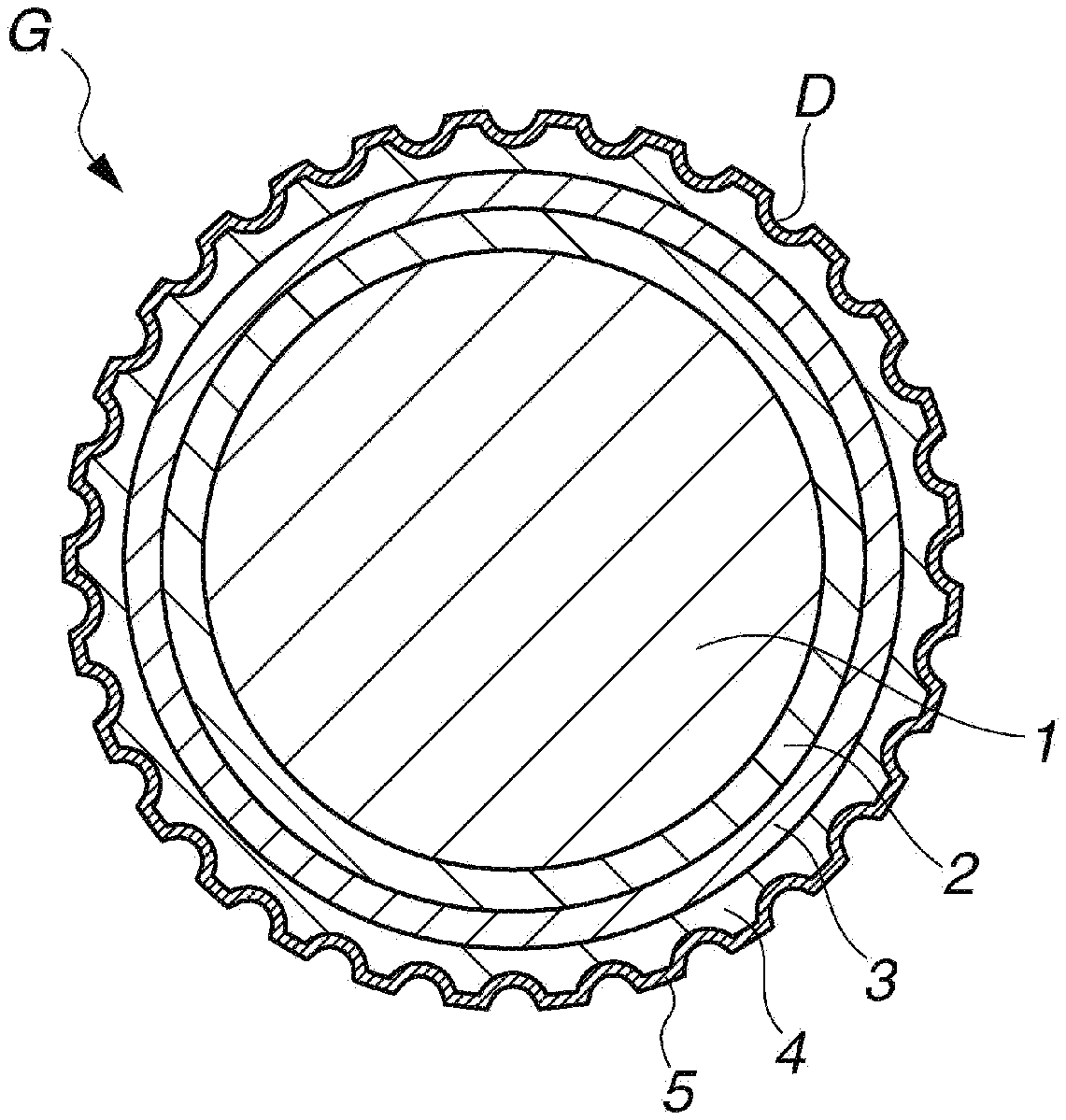
[0019] The FIGURE is a schematic cross-sectional view of a golf ball having a four-layer construction according to one embodiment of the invention.
DESCRIPTION OF THE PREFERRED EMBODIMENTS
[0020] The objects, features and advantages of the invention will become more apparent from the following detailed description taken in conjunction with the appended diagrams.
[0021] The golf ball of the invention has a core and a cover. In this invention, the cover refers to the member positioned as the outermost layer in the ball construction and typically is formed by injection molding or the like. Numerous dimples are typically formed on the outer surface of the cover at the same time that the cover material is injection molded.
[0022] The core has a diameter of preferably at least 34.0 mm, more preferably at least 34.5 mm, and even more preferably at least 35.0 mm. The upper limit is preferably not more than 37.0 mm, more preferably not more than 36.5 mm, and even more preferably not more than 36.0 mm. When the core diameter is too small, the spin rate on shots with a driver (W #1) may become high, as a result of which it may not be possible to achieve the desired distance. On the other hand, when the core diameter is too large, the durability to repeated impact may worsen or the feel at impact may worsen.
[0023] The core has an amount of compressive deformation (mm) when subjected to a final load of 1,275 N (130 kgf) from an initial load of 98 N (10 kgf) which, although not particularly limited, is preferably at least 3.0 mm, more preferably at least 3.5 mm, and even more preferably at least 4.0 mm. The upper limit is preferably not more than 7.0 mm, more preferably not more than 6.0 mm, and even more preferably not more than 5.0 mm. When the compressive deformation of the core is too small, i.e., when the core is too hard, the spin rate of the ball may rise excessively and a good distance may not be achieved, or the feel at impact may be too hard. On the other hand, when the compressive deformation of the core is too large, i.e., when the core is too soft, the ball rebound may become too low and a good distance may not be achieved, the feel at impact may be too soft, or the durability to cracking on repeated impact may worsen.
[0024] The core is formed of a single layer or a plurality of layers of rubber material. A rubber composition can be prepared as this core-forming rubber material by using a base rubber as the chief component and including, together with this, other ingredients such as a co-crosslinking agent, an organic peroxide, an inert filler and an organosulfur compound. It is preferable to use polybutadiene as the base rubber.
[0025] Commercial products may be used as the polybutadiene. Illustrative examples include BR01, BR51 and BR730 (all products of JSR Corporation). The proportion of polybutadiene within the base rubber is preferably at least 60 wt %, and more preferably at least 80 wt %. Rubber ingredients other than the above polybutadienes may be included in the base rubber, provided that doing so does not detract from the advantageous effects of the invention. Examples of rubber ingredients other than the above polybutadienes include other polybutadienes and also other diene rubbers, such as styrene-butadiene rubbers, natural rubbers, isoprene rubbers and ethylene-propylene-diene rubbers.
[0026] Examples of co-crosslinking agents include unsaturated carboxylic acids and metal salts of unsaturated carboxylic acids. Specific examples of unsaturated carboxylic acids include acrylic acid, methacrylic acid, maleic acid and fumaric acid. The use of acrylic acid or methacrylic acid is especially preferred. Metal salts of unsaturated carboxylic acids are exemplified by, without particular limitation, the above unsaturated carboxylic acids that have been neutralized with desired metal ions. Specific examples include the zinc salts and magnesium salts of methacrylic acid and acrylic acid. The use of zinc acrylate is especially preferred.
[0027] The unsaturated carboxylic acid and/or metal salt thereof is included in an amount, per 100 parts by weight of the base rubber, which is typically at least 5 parts by weight, preferably at least 9 parts by weight, and more preferably at least 13 parts by weight. The amount included is typically not more than 60 parts by weight, preferably not more than 50 parts by weight, and more preferably not more than 40 parts by weight. Too much may make the core too hard, giving the ball an unpleasant feel at impact, whereas too little may lower the rebound.
[0028] Commercial products may be used as the organic peroxide. Examples of such products that may be suitably used include Percumyl D, Perhexa C-40 and Perhexa 3M (all from NOF Corporation), and Luperco 231XL (from AtoChem Co.). One of these may be used alone, or two or more may be used together. The amount of organic peroxide included per 100 parts by weight of the base rubber is preferably at least 0.1 part by weight, more preferably at least 0.3 part by weight, even more preferably at least 0.5 part by weight, and most preferably at least 0.6 part by weight. The upper limit is preferably not more than 5 parts by weight, more preferably not more than 4 parts by weight, even more preferably not more than 3 parts by weight, and most preferably not more than 2.5 parts by weight. When too much or too little is included, it may not be possible to obtain a ball having a good feel, durability and rebound.
[0029] Another compounding ingredient typically included with the base rubber is an inert filler, preferred examples of which include zinc oxide, barium sulfate and calcium carbonate. One of these may be used alone, or two or more may be used together. The amount of inert filler included per 100 parts by weight of the base rubber is preferably at least 1 part by weight, and more preferably at least 5 parts by weight. The upper limit is preferably not more than 50 parts by weight, more preferably not more than 40 parts by weight, and even more preferably not more than 35 parts by weight. Too much or too little inert filler may make it impossible to obtain a proper weight and a suitable rebound.
[0030] In addition, an antioxidant may be optionally included. Illustrative examples of suitable commercial antioxidants include Nocrac NS-6 and Nocrac NS-30 (both available from Ouchi Shinko Chemical Industry Co., Ltd.), and Yoshinox 425 (available from Yoshitomi Pharmaceutical Industries, Ltd.). One of these may be used alone, or two or more may be used together.
[0031] The amount of antioxidant included per 100 parts by weight of the base rubber is set to 0 part by weight or more, preferably at least 0.05 part by weight, and more preferably at least 0.1 part by weight. The upper limit is set to preferably not more than 3 parts by weight, more preferably not more than 2 parts by weight, even more preferably not more than 1 part by weight, and most preferably not more than 0.5 part by weight. Too much or too little antioxidant may make it impossible to achieve a suitable ball rebound and durability.
[0032] An organosulfur compound may be included in the core in order to impart a good resilience. The organosulfur compound is not particularly limited, provided it can enhance the rebound of the golf ball. Exemplary organosulfur compounds include thiophenols, thionaphthols, halogenated thiophenols, and metal salts of these. Specific examples include pentachlorothiophenol, pentafluorothiophenol, pentabromothiophenol, p-chlorothiophenol, the zinc salt of pentachlorothiophenol, the zinc salt of pentafluorothiophenol, the zinc salt of pentabromothiophenol, the zinc salt of p-chlorothiophenol, and any of the following having 2 to 4 sulfur atoms: diphenylpolysulfides, dibenzylpolysulfides, dibenzoylpolysulfides, dibenzothiazoylpolysulfides and dithiobenzoylpolysulfides. The use of the zinc salt of pentachlorothiophenol is especially preferred.
[0033] The amount of organosulfur compound included per 100 parts by weight of the base rubber is 0 part by weight or more, and it is recommended that the amount be preferably at least 0.1 part by weight, and even more preferably at least 0.2 part by weight, and that the upper limit be preferably not more than 5 parts by weight, more preferably not more than 3 parts by weight, and even more preferably not more than 2 parts by weight. Including too much organosulfur compound may make a greater rebound-improving effect (particularly on shots with a W #1) unlikely to be obtained, may make the core too soft or may worsen the feel of the ball at impact. On the other hand, including too little may make a rebound-improving effect unlikely.
[0034] Decomposition of the organic peroxide within the core formulation can be promoted by the direct addition of water (or a water-containing material) to the core material. The decomposition efficiency of the organic peroxide within the core-forming rubber composition is known to change with temperature; starting at a given temperature, the decomposition efficiency rises with increasing temperature. If the temperature is too high, the amount of decomposed radicals rises excessively, leading to recombination between radicals and, ultimately, deactivation. As a result, fewer radicals act effectively in crosslinking. Here, when a heat of decomposition is generated by decomposition of the organic peroxide at the time of core vulcanization, the vicinity of the core surface remains at substantially the same temperature as the temperature of the vulcanization mold, but the temperature near the core center, due to the build-up of heat of decomposition by the organic peroxide which has decomposed from the outside, becomes considerably higher than the mold temperature. In cases where water (or a water-containing material) is added directly to the core, because the water acts to promote decomposition of the organic peroxide, radical reactions like those described above can be made to differ at the core center and core surface. That is, decomposition of the organic peroxide is further promoted near the center of the core, bringing about greater radical deactivation, which leads to a further decrease in the amount of active radicals. As a result, it is possible to obtain a core in which the crosslink densities at the core center and the core surface differ markedly. It is also possible to obtain a core having different dynamic viscoelastic properties at the core center.
[0035] The water included in the core material is not particularly limited, and may be distilled water or tap water. The use of distilled water that is free of impurities is especially preferred. The amount of water included per 100 parts by weight of the base rubber is preferably at least 0.1 part by weight, and more preferably at least 0.3 part by weight. The upper limit is preferably not more than 5 parts by weight, and more preferably not more than 4 parts by weight.
[0036] The core can be produced by vulcanizing and curing the rubber composition containing the above ingredients. For example, the core can be produced by using a Banbury mixer, roll mill or other mixing apparatus to intensively mix the rubber composition, subsequently compression molding or injection molding the mixture in a core mold, and curing the resulting molded body by suitably heating it under conditions sufficient to allow the organic peroxide or co-crosslinking agent to act, such as at a temperature of between 100 and 200.degree. C., preferably between 140 and 180.degree. C., for 10 to 40 minutes.
[0037] The core may consist of a single layer alone, or may be formed as a two-layer core consisting of an inner core layer and an outer core layer. When the core is formed as a two-layer core consisting of an inner core layer and an outer core layer, the inner core layer and outer core layer materials may each be composed primarily of the above-described rubber material. Also, the rubber material making up the outer core layer encasing the inner core layer may be the same as or different from the inner core layer material. The details here are the same as those given above for the ingredients of the core-forming rubber material.
[0038] Next, the core hardness profile is described.
[0039] The core center has a hardness (Cc) which, expressed on the Shore C hardness scale, is preferably at least 50, more preferably at least 53, and even more preferably at least 55. The upper limit is preferably not more than 65, more preferably not more than 62, and even more preferably not more than 60. When this value is too large, the feel at impact may become hard, or the spin rate on full shots may rise, as a result of which the intended distance may not be achieved. On the other hand, when this value is too small, the rebound may become low, resulting in a poor distance, or the durability to cracking on repeated impact may worsen. The Shore C hardness is the hardness value measured with a Shore C durometer in general accordance with ASTM D2240. Although, for example, the timing of the read-off of measurements differs from that in the technique used for measuring JIS-C hardness, the measured Shore C hardness values do not differ much from and, in fact, are closely similar to the JIS-C values.
[0040] Alternatively, the core center hardness (Cc) expressed on the Shore D hardness scale is preferably at least 26, more preferably at least 28, and even more preferably at least 30. The upper limit is preferably not more than 40, more preferably not more than 37, and even more preferably not more than 34.
[0041] The core surface has a hardness (Cs) which, expressed on the Shore C hardness scale, is preferably at least 73, more preferably at least 77, and even more preferably at least 80. The upper limit is preferably not more than 89, more preferably not more than 87, and even more preferably not more than 85. A value outside of this range may lead to undesirable results similar to those described above for the core center hardness (Cc).
[0042] Alternatively, the core surface hardness (Cs) expressed on the Shore D hardness scale is preferably at least 40, more preferably at least 43, and even more preferably at least 45. The upper limit is preferably not more than 54, more preferably not more than 52, and even more preferably not more than 50.
[0043] The difference between the core surface hardness (Cs) and the core center hardness (Cc), expressed on the Shore C hardness scale, is preferably at least 20, more preferably at least 22, and even more preferably at least 24. The upper limit is preferably not more than 32, and more preferably not more than 30. When this value is too small, the ball spin rate-lowering effect on shots with a driver may be inadequate, resulting in a poor distance. When this value is too large, the initial velocity of the ball when struck may decrease, resulting in a poor distance, or the durability to cracking on repeated impact may worsen.
[0044] Next, the cover is described.
[0045] The cover has a material hardness on the Shore D scale which, although not particularly limited, is preferably at least 55, more preferably at least 59, and even more preferably at least 61. The upper limit is preferably not more than 70, more preferably not more than 68, and even more preferably not more than 65. The surface hardness of the cover (also referred to herein as the "ball surface hardness"), expressed on the Shore D scale, is preferably at least 61, more preferably at least 65, and even more preferably at least 67. The upper limit is preferably not more than 76, more preferably not more than 74, and even more preferably not more than 71. When the material hardness of the cover and the ball surface hardness are too much lower than the above respective ranges, the spin rate of the ball on shots with a driver (W #1) may rise and the ball initial velocity may decrease, as a result of which a good distance may not be obtained. On the other hand, when the material hardness of the cover and the ball surface hardness are too high, the durability to cracking on repeated impact may worsen.
[0046] The cover has a thickness of preferably at least 0.6 mm, more preferably at least 0.8 mm, and even more preferably at least 1.1 mm. The upper limit in the cover thickness is preferably not more than 1.5 mm, more preferably not more than 1.4 mm, and even more preferably not more than 1.3 mm. When the cover is too thin, the durability to cracking on repeated impact may worsen. When the cover is too thick, the spin rate of the ball on shots with a driver (W #1) may rise excessively and a good distance may not be obtained, or the feel at impact in the short game and on shots with a putter may be too hard.
[0047] Various types of thermoplastic resins, particularly ionomer resins, that are employed as cover stock in golf balls may be suitably used as the cover material. Commercial products may be used as the ionomer resin. Alternatively, the cover-forming resin material that is used may be one obtained by blending, of commercially available ionomer resins, a high-acid ionomer resin having an acid content of at least 18 wt % into a conventional ionomer resin. The high rebound and the spin rate-lowering effect obtained with such a blend make it possible to achieve a good distance on shots with a driver (W #1). The amount of such a high-acid ionomer resin included per 100 parts by weight of the resin material is preferably at least 10 wt %, more preferably at least 30 wt %, and even more preferably at least 60 wt %. The upper limit is generally up to 100 wt %, preferably up to 90 wt %, and more preferably up to 80 wt %. When the content of this high-acid ionomer resin is too low, the spin rate on shots with a driver (W #1) may rise, resulting in a poor distance. On the other hand, when the content of the high-acid ionomer resin is too high, the durability to cracking on repeated impact may worsen.
[0048] The envelope layer and intermediate layer described below may be provided between the core and cover. Suitable ball constructions in the present invention are not limited to two-piece golf balls having a core and a single-layer cover; three-piece golf balls and four-piece golf balls may also be used. The use of golf balls composed of four layers--a core, an envelope layer, an intermediate layer and a cover--is especially suitable. Such golf balls are exemplified by the golf ball G shown in the FIGURE. The golf ball G in the FIGURE has a core 1, an envelope layer 2 encasing the core 1, an intermediate layer 3 encasing the envelope layer 2, and a cover 4 encasing the intermediate layer 3. This cover 4 is positioned as the outermost layer, aside from a paint film layer, in the layer structure of the golf ball. The intermediate layer and the envelope layer may each be either a single layer or may be formed of two or more layers. Numerous dimples D are generally formed on the surface of the cover (outermost layer) 4 in order to enhance the aerodynamic properties. In addition, a paint film layer 5 is formed on the surface of the cover 4.
[0049] Next, the envelope layer is described.
[0050] The envelope layer has a material hardness on the Shore D scale which, although not particularly limited, is preferably at least 20, more preferably at least 23, and even more preferably at least 27. The upper limit is preferably not more than 45, more preferably not more than 42, and even more preferably not more than 40. The surface hardness of the sphere obtained by encasing the core with the envelope layer (envelope layer-encased sphere), expressed on the Shore D scale, is preferably at least 28, more preferably at least 31, and even more preferably at least 35. The upper limit is preferably not more than 53, more preferably not more than 50, and even more preferably not more than 48. When the material and surface hardnesses of the envelope layer are lower than the above respective ranges, the spin rate of the ball on full shots may rise excessively, resulting in a poor distance, or the durability of the ball to repeated impact may worsen. On the other hand, when the material and surface hardnesses are too high, the durability to cracking on repeated impact may worsen or the spin rate on full shots may rise, as a result of which, particularly on low head speed shots, a good distance may not be achieved, and the feel at impact may worsen.
[0051] The envelope layer has a thickness of preferably at least 0.7 mm, more preferably at least 0.9 mm, and even more preferably at least 1.1 mm. The upper limit in the envelope layer thickness is preferably not more than 1.5 mm, more preferably not more than 1.4 mm, and even more preferably not more than 1.3 mm. When this envelope layer is too thin, the durability to cracking on repeated impact may worsen or the feel at impact may worsen. When the envelope layer is too thick, the spin rate of the ball on full shots may rise and a good distance may not be achieved.
[0052] The envelope layer material is not particularly limited, although various types of thermoplastic resin materials may be suitably employed for this purpose. For example, use can be made of ionomer resins, urethane, amide, ester, olefin or styrene-type thermoplastic elastomers, and mixtures thereof. From the standpoint of obtaining a good rebound in the desired hardness range, the use of a thermoplastic polyether ester elastomer is especially suitable.
[0053] The sphere obtained by encasing the core with the envelope layer (envelope layer-encased sphere) has an amount of compressive deformation (mm) when subjected to a final load of 1,275 N (130 kgf) from an initial load of 98 N (10 kgf) which, although not particularly limited, is preferably at least 3.4 mm, more preferably at least 3.8 mm, and even more preferably at least 3.9 mm. The upper limit is preferably not more than 4.7 mm, more preferably not more than 4.5 mm, and even more preferably not more than 4.3 mm. When the compressive deformation of the sphere is too small, that is, when the sphere is too hard, the ball spin rate may rise excessively, resulting in a poor distance, or the feel at impact may become too hard. On the other hand, when the compressive deformation of the sphere is too large, that is, when the sphere is too soft, the ball rebound may become too low, resulting in a poor distance, the feel at impact may become too soft, or the durability to cracking on repeated impact may worsen.
[0054] Next, the intermediate layer is described.
[0055] The intermediate layer has a material hardness on the Shore D scale which, although not particularly limited, is preferably at least 40, more preferably at least 45, and even more preferably at least 50. The upper limit is preferably not more than 62, more preferably not more than 60, and even more preferably not more than 58. The surface hardness of the sphere obtained by encasing the envelope layer-encased sphere with the intermediate layer (intermediate layer-encased sphere), expressed on the Shore D scale, is preferably at least 46, more preferably at least 51, and even more preferably at least 56. The upper limit is preferably not more than 68, more preferably not more than 66, and even more preferably not more than 64. When the material and surface hardnesses of the intermediate layer are lower than the above respective ranges, the spin rate of the ball on full shots may rise excessively, resulting in a poor distance, or the ball may cease to have a solid feel at impact. On the other hand, when the material and surface hardnesses are too high, the durability to cracking on repeated impact may worsen or the ball may cease to have a soft feel at impact.
[0056] The intermediate layer has a thickness of preferably at least 0.7 mm, more preferably at least 0.9 mm, and even more preferably at least 1.1 mm. The upper limit in the intermediate layer thickness is preferably not more than 1.5 mm, more preferably not more than 1.4 mm, and even more preferably not more than 1.35 mm. When the intermediate layer is too thin, the durability to cracking on repeated impact may worsen or the feel at impact may worsen. When the intermediate layer is too thick, the spin rate of the ball on full shots may rise and a good distance may not be obtained.
[0057] The intermediate layer-forming material is not particularly limited and may be a known resin. Examples of preferred materials include resin compositions containing as the essential ingredients:
100 parts by weight of a resin component composed of, in admixture,
[0058] (A) a base resin of (a-1) an olefin-unsaturated carboxylic acid random copolymer and/or a metal ion neutralization product of an olefin-unsaturated carboxylic acid random copolymer mixed with (a-2) an olefin-unsaturated carboxylic acid-unsaturated carboxylic acid ester random terpolymer and/or a metal ion neutralization product of an olefin-unsaturated carboxylic acid-unsaturated carboxylic acid ester random terpolymer in a weight ratio between 100:0 and 0:100, and
[0059] (B) a non-ionomeric thermoplastic elastomer in a weight ratio between 100:0 and 50:50;
[0060] (C) from 5 to 80 parts by weight of a fatty acid and/or fatty acid derivative having a molecular weight of from 228 to 1,500; and
[0061] (D) from 0.1 to 17 parts by weight of a basic inorganic metal compound capable of neutralizing un-neutralized acid groups in components A and C.
[0062] Components A to D in the intermediate layer-forming resin material described in, for example, JP-A 2010-253268 may be advantageously used as above components A to D.
[0063] A non-ionomeric thermoplastic elastomer may be included in the intermediate layer material. The amount of non-ionomeric thermoplastic elastomer included is preferably from 0 to 50 parts by weight per 100 parts by weight of the total amount of the base resin.
[0064] Exemplary non-ionomeric thermoplastic elastomers include polyolefin elastomers (including polyolefin and metallocene polyolefins), polystyrene elastomers, diene polymers, polyacrylate polymers, polyamide elastomers, polyurethane elastomers, polyester elastomers and polyacetals.
[0065] Depending on the intended use, optional additives may be suitably included in the intermediate layer material. For example, pigments, dispersants, antioxidants, ultraviolet absorbers and light stabilizers may be added. When these additives are included, the amount added per 100 parts by weight of the overall base resin is preferably at least 0.1 part by weight, and more preferably at least 0.5 part by weight. The upper limit is preferably not more than 10 parts by weight, and more preferably not more than 4 parts by weight.
[0066] The sphere obtained by encasing the envelope-encased sphere with the intermediate layer (intermediate layer-encased sphere) has an amount of compressive deformation when subjected to a final load of 1,275 N (130 kgf) from an initial load of 98 N (10 kgf) which, although not particularly limited, is preferably at least 3.3 mm, more preferably at least 3.45 mm, and even more preferably at least 3.6 mm. The upper limit is preferably not more than 4.2 mm, more preferably not more than 4.0 mm, and even more preferably not more than 3.8 mm. When the compressive deformation of the sphere is too small, that is, when the sphere is too hard, the ball spin rate may rise excessively, resulting in a poor distance, or the feel at impact may become too hard. On the other hand, when the compressive deformation of the sphere is too large, that is, when the sphere is too soft, the ball rebound may become too low, resulting in a poor distance, the feel at impact may become too soft, or the durability to cracking on repeated impact may worsen.
[0067] The manufacture of multi-piece solid golf balls in which the above-described core, envelope layer, intermediate layer and cover (outermost layer) are formed as successive layers may be carried out by a customary method such as a known injection molding process. For example, a multi-piece golf ball can be obtained by successively injection-molding the envelope layer material and the intermediate layer material over the core so as to obtain an intermediate layer-encased sphere, and then injection-molding the cover material over the intermediate layer-encased sphere. Alternatively, the encasing layers may each be formed by enclosing the sphere to be encased within two half-cups that have been pre-molded into hemispherical shapes and then molding under applied heat and pressure.
[0068] The compressive deformation A of the inventive golf ball when subjected to a final load of 5 kg from an initial load state of 0.2 kg is 0.21 mm or less, preferably 0.19 mm or less, and more preferably 0.17 mm or less. The lower limit is preferably at least 0.10 mm, and more preferably at least 0.12 mm. When this value becomes smaller, in cases where this is attributable to the cover hardness, the cover may be too hard and the durability of the ball to cracking under repeated impact may worsen. Alternatively, when this value becomes smaller owing to compression of an inner layer, the feel of the ball on full shots may become too hard. On the other hand, when the above value becomes larger, in cases where this is attributable to the cover hardness, the spin rate of the ball on full shots may end up rising, so that a good distance is not achieved. Alternatively, when this value becomes larger owing to compression of an inner layer, the ball may cease to have a crisp feel on full shots and a good distance may not be achieved.
[0069] The compressive deformation B of the inventive golf ball when subjected to a final load of 30 kg from an initial load state of 5 kg is preferably at least 0.72 mm, more preferably at least 0.73 mm, and even more preferably at least 0.74 mm. The upper limit is preferably not more than 0.90 mm, more preferably not more than 0.88 mm, and even more preferably not more than 0.86 mm. If this value is small, the ball may have too hard a feel when struck with a utility club (also abbreviated below as "UT") or an iron. On the other hand, if this value is large, the crisp feel of the ball when struck with a utility club or an iron may diminish and a good distance may not be achieved.
[0070] The compressive deformation C of the inventive golf ball when subjected to a final load of 60 kg from an initial load state of 5 kg is preferably at least 1.55 mm, more preferably at least 1.56 mm, and even more preferably at least 1.58 mm. The upper limit is preferably not more than 1.80 mm, more preferably not more than 1.77 mm, and even more preferably not more than 1.74 mm. If this value is small, the ball may have too hard a feel at impact when struck with a utility club or an iron. On the other hand, if this value is large, the crisp feel of the ball when struck with a utility club or an iron may diminish and a good distance may not be achieved.
[0071] The compressive deformation D of the inventive golf ball when subjected to a final load of 130 kg from an initial load state of 10 kg is preferably at least 2.80 mm, more preferably at least 2.90 mm, and even more preferably at least 2.95 mm. The upper limit is preferably not more than 3.40 mm, more preferably not more than 3.30 mm, and even more preferably not more than 3.15 mm. If this value is small, the spin rate of the ball may rise, resulting in a poor distance, or the feel of the ball may become too hard. On the other hand, if this value is large, the ball rebound may become too low, resulting in a poor distance, the feel of the ball may become too soft, or the durability to cracking under repeated impact may worsen.
[0072] The ratio D/C between compressive deformation D and compressive deformation C is preferably from 1.80 to 1.90. Outside of this range, the solid feel of the ball may worsen and impact conditions under which the distance falls may arise.
[0073] The ratio D/B between compressive deformation D and compressive deformation B is preferably at least 3.65, more preferably at least 3.67, and even more preferably at least 3.69. The upper limit is preferably not more than 4.20, more preferably not more than 4.15, and even more preferably not more than 4.10. Outside of this range, the solid feel of the ball may worsen and impact conditions under which the distance falls may arise.
[0074] The ratio D/A between compressive deformation D and compressive deformation A is preferably at least 16.0, more preferably at least 17.0, and even more preferably at least 17.5. The upper limit is preferably not more than 25.0, more preferably not more than 24.0, and even more preferably not more than 23.0. Outside of this range, the ball may become too receptive to spin or the initial velocity of the ball when struck may decrease and, depending on the number of the golf club, the distance may decrease.
Surface Hardness Relationships Among Layers
[0075] In this invention, it is desirable for the hardness relationships among the layers to satisfy formula (1) below:
(1) Shore D hardness at cover surface>Shore D hardness at intermediate layer surface>Shore D hardness at envelope layer surface>Shore D hardness at core center.
[0076] Here, the hardness at the cover surface refers to the surface hardness of the ball. The hardness at the intermediate layer surface refers to the surface hardness of the intermediate layer-encased sphere, and the hardness at the envelope layer surface refers to the surface hardness of the envelope layer-encased sphere.
[0077] When the above hardness relationship is not satisfied, a good flight performance and a feel at impact that is both soft and solid may not be obtained.
[0078] As indicated in the above formula, the cover surface hardness is larger than the intermediate layer surface hardness. The difference therebetween, i.e., the "cover surface hardness-intermediate layer surface hardness" value, expressed on the Shore D hardness scale, is preferably from 1 to 14, more preferably from 3 to 10, and even more preferably from 5 to 8. When this value is small, the spin rate of the ball on full shots may end up rising, as a result of which a good distance may not be achieved. On the other hand, when this value is large, the feel at impact may worsen or the durability to cracking on repeated impact may worsen.
[0079] As indicated in the above formula, the intermediate layer surface hardness is larger than the envelope layer surface hardness. The difference therebetween, i.e., the "intermediate layer surface hardness-envelope layer surface hardness" value, expressed on the Shore D hardness scale, is preferably from 10 to 28, more preferably from 13 to 26, and even more preferably from 15 to 24. When this value is small, the spin rate of the ball on full shots may end up rising, as a result of which a good distance may not be achieved. On the other hand, when this value is large, the feel at impact may worsen or the durability to cracking on repeated impact may worsen.
[0080] As indicated in the above formula, the envelope layer surface hardness is larger than the core center hardness. The difference therebetween, i.e., the "envelope layer surface hardness-core center hardness" value, expressed on the Shore D hardness scale, is preferably from 3 to 23, more preferably from 5 to 20, and even more preferably from 7 to 17. Also, the "envelope layer surface hardness-core surface hardness" value, expressed on the Shore D hardness scale, is preferably from -20 to 8, more preferably from -15 to 5, and even more preferably from -10 to 2. When these values are small, the spin rate of the ball on full shots may end up rising, as a result of which a good distance may not be achieved. On the other hand, when these values are large, the feel at impact may worsen or the durability to cracking on repeated impact may worsen.
[0081] Also, the "core surface hardness-ball surface hardness" value, expressed on the Shore D hardness scale, is preferably from -30 to -10, more preferably from -27 to -14, and even more preferably from -24 to -17. When this value is small, the solid feel of the ball at impact may be lost or the durability to cracking on repeated impact may worsen. On the other hand, when this value is large, impact conditions may emerge under which the spin rate of the ball rises and a good distance is not achieved.
Compressive Deformation Relationships among Encased Spheres
[0082] Letting P and Q be the respective compressive deformations (mm) of the core and the envelope layer-encased sphere when subjected to a final load of 1,275 N (130 kg) from an initial load of 98 N (10 kgf), the value P-Q is preferably from 0 to 0.6 mm, more preferably from 0.1 to 0.5 mm, and even more preferably from 0.2 to 0.4 mm. When this value is small, the feel at impact may worsen or the durability to cracking under repeated impact may worsen. When this value is large, the spin rate of the ball on full shots may end up rising, as a result of which a good distance may not be obtained.
[0083] Letting Q and R be the respective compressive deformations (mm) of the envelope layer-encased sphere and the intermediate layer-encased sphere when subjected to a final load of 1,275 N (130 kg) from an initial load of 98 N (10 kgf), the value Q-R is preferably from 0.1 to 0.8 mm, more preferably from 0.2 to 0.7 mm, and even more preferably from 0.3 to 0.6 mm. When this value is small, the spin rate of the ball on full shots may end up rising, as a result of which a good distance may not be achieved. On the other hand, when this value is large, the feel at impact may worsen or the durability to cracking on repeated impact may worsen.
[0084] Letting P and D be the respective compressive deformations (mm) of the core and the ball when subjected to a final load of 1,275 N (130 kg) from an initial load of 98 N (10 kgf), the value P-D is preferably from 1.0 to 1.7 mm, more preferably from 1.1 to 1.6 mm, and even more preferably from 1.2 to 1.5 mm. When this value is small, the spin rate of the ball on full shots may end up rising, as a result of which a good distance may not be achieved. On the other hand, when this value is large, the solid feel at impact may be lost or the durability to cracking on repeated impact may worsen.
Initial Velocity Relationships Among Encased Spheres
[0085] The "ball initial velocity-core initial velocity" value is preferably from -0.8 to 0 m/s, more preferably from -0.6 to -0.1 m/s, and even more preferably from -0.5 to -0.3 m/s. When this value is too small, the rebound of the overall ball may become low or the spin rate on full shots may rise excessively, as a result of which a good distance may not be obtained. On the other hand, when this value is too large, the cover may become hard and the durability to cracking on repeated impact may worsen. As used herein, "initial velocity" refers to the initial velocity of the various spheres--i.e., the ball, the core, and the subsequently described intermediate layer-encased sphere and envelope layer-encased sphere--as measured by the method, set forth in the Rules of Golf, for measuring the initial velocity of golf balls using an initial velocity measuring apparatus of the same type as the USGA drum rotation-type initial velocity instrument.
[0086] The "ball initial velocity-intermediate layer-encased sphere initial velocity" value is preferably from -0.4 to 0.4 m/s, more preferably from -0.3 to 0.3 m/s, and even more preferably from -0.2 to 0.1 m/s. When this value is too large, the spin rate-lowering effect on full shots may be inadequate and a good distance may not be achieved, or the cover may become hard, worsening the durability to cracking on repeated impact. On the other hand, when this value is too small, the cover may become soft, as a result of which the spin rate on full shots may rise, resulting in a poor distance, or a solid feel at impact may not be obtained.
[0087] The "intermediate layer-encased sphere initial velocity-envelope layer-encased sphere initial velocity" value is at least 0.0 m/s, preferably from 0.1 to 0.4 m/s, and more preferably from 0.15 to 0.3 m/s. When this value is too small, the spin rate-lowering effect on full shots may be inadequate and a good distance may not be achieved. On the other hand, when this value is too large, the intermediate layer material may become brittle and the durability to cracking on repeated impact may worsen.
[0088] Numerous dimples may be formed on the outside surface of the cover serving as the outermost layer. The number of dimples arranged on the cover surface, although not particularly limited, is preferably at least 250, more preferably at least 300, and even more preferably at least 320. The upper limit is preferably not more than 380, more preferably not more than 350, and even more preferably not more than 340. When the number of dimples is higher than this range, the ball trajectory may become lower, as a result of which the distance traveled by the ball may decrease. On the other hand, when the number of dimples is lower that this range, the ball trajectory may become higher, as a result of which a good distance may not be achieved.
[0089] The dimple shapes used may be of one type or may be a combination of two or more types suitably selected from among, for example, circular shapes, various polygonal shapes, dewdrop shapes and oval shapes. When circular dimples are used, the dimple diameter may be set to at least about 2.5 mm and up to about 6.5 mm, and the dimple depth may be set to at least 0.08 mm and up to 0.30 mm.
[0090] In order for the aerodynamic properties to be fully manifested, it is desirable for the dimple coverage ratio on the spherical surface of the golf ball, i.e., the dimple surface coverage SR, which is the sum of the individual dimple surface areas, each defined by the flat plane circumscribed by the edge of a dimple, as a percentage of the spherical surface area of the ball were the ball to have no dimples thereon, to be set to at least 70% and not more than 90%. Also, to optimize the ball trajectory, it is desirable for the value V.sub.0, defined as the spatial volume of the individual dimples below the flat plane circumscribed by the dimple edge, divided by the volume of the cylinder whose base is the flat plane and whose height is the maximum depth of the dimple from the base, to be set to at least 0.35 and not more than 0.80. Moreover, it is preferable for the ratio VR of the sum of the volumes of the individual dimples, each formed below the flat plane circumscribed by the edge of a dimple, with respect to the volume of the ball sphere were the ball surface to have no dimples thereon, to be set to at least 0.6% and not more than 1.0%. Outside of the above ranges in these respective values, the resulting trajectory may not enable a good distance to be obtained and so the ball may fail to travel a fully satisfactory distance.
[0091] To ensure a good ball appearance, it is preferable to apply a clear coating onto the cover surface. The coating composition used in clear coating is preferably one which uses two types of polyester polyol as the base resin and uses a polyisocyanate as the curing agent. In this case, various organic solvents can be admixed depending on the intended coating conditions. Examples of organic solvents that can be used include aromatic solvents such as toluene, xylene and ethylbenzene; ester solvents such as ethyl acetate, butyl acetate, propylene glycol methyl ether acetate and propylene glycol methyl ether propionate; ketone solvents such as acetone, methyl ethyl ketone, methyl isobutyl ketone and cyclohexanone; ether solvents such as diethylene glycol dimethyl ether, diethylene glycol diethyl ether and dipropylene glycol dimethyl ether; alicyclic hydrocarbon solvents such as cyclohexane, methyl cyclohexane and ethyl cyclohexane; and petroleum hydrocarbon-based solvents such as mineral spirits.
[0092] The paint film layer (coating layer) obtained by clear coating has a hardness which, on the Shore C hardness scale, is preferably from 40 to 80, more preferably from 47 to 72, and even more preferably from 55 to 65. When the coating layer is too soft, mud may tend to stick to the surface of the ball when used for golfing. On the other hand, when the coating layer is too hard, it may tend to peel off when the ball is struck.
[0093] The "core center hardness (Cc)-coating layer hardness" value on the Shore C hardness scale is preferably from -15 to 5, more preferably from -10 to 0, and even more preferably from -7 to -5. When this value falls outside of the above range, the spin rate of the ball on full shots may end up rising, as a result of which a good distance may not be achieved.
[0094] The paint film layer (coating layer) has a thickness of typically from 9 to 22 .mu.m, preferably from 11 to 20 .mu.m, and more preferably from 13 to 18 .mu.m.
[0095] The multi-piece solid golf ball of the invention can be made to conform to the Rules of Golf for play. The inventive ball may be formed to a diameter which is such that the ball does not pass through a ring having an inner diameter of 42.672 mm and is not more than 42.80 mm, and to a weight which is preferably between 45.0 and 45.93 g.
EXAMPLES
[0096] The following Examples and Comparative Examples are provided to illustrate the invention, and are not intended to limit the scope thereof.
Examples 1 to 4, Comparative Examples 1 to 5
Formation of Core
[0097] Solid cores were produced by preparing rubber compositions for the respective Examples and Comparative Examples shown in Table 1, and then molding/vulcanizing the compositions under vulcanization conditions of 155.degree. C. and 15 minutes.
TABLE-US-00001 TABLE 1 Core formulation Example Comparative Example (pbw) 1 2 3 4 1 2 3 4 5 Polybutadiene A 80 80 80 80 80 80 80 80 100 Polybutadiene B 20 20 20 20 20 20 20 20 Zinc acrylate 28.2 26.9 29.6 28.2 28.2 29.6 30.9 29.6 27.0 Organic peroxide (1) 1.0 1.0 1.0 1.0 1.0 1.0 1.0 1.0 0.6 Organic peroxide (2) 0.6 Water 1.0 1.0 1.0 1.0 1.0 1.0 1.0 1.0 Antioxidant 0.1 0.1 0.1 0.1 0.1 0.1 0.1 0.1 0.1 Barium sulfate 27.4 27.9 26.8 27.4 27.4 26.8 26.3 26.8 24.3 Zinc oxide 4.0 4.0 4.0 4.0 4.0 4.0 4.0 4.0 4.0 Zinc salt of pentachlorothiophenol 0.3 0.3 0.3 0.3 0.3 0.3 0.3 0.3 Details on the ingredients mentioned in Table 1 are given below. Polybutadiene A: Available under the trade name "BR 01" from JSR Corporation Polybutadiene B: Available under the trade name "BR 51" from JSR Corporation Zinc acrylate: Available as "ZN-DA85S" from Nippon Shokubai Co., Ltd. Organic Peroxide (1): Dicumyl peroxide, available under the trade name "Percumyl D" from NOF Corporation Organic Peroxide (2): A mixture of 1,1-di(t-butylperoxy)cyclohexane and silica, available under the trade name "Perhexa C-40" from NOF Corporation Water: Pure water (from Seiki Chemical Industrial Co., Ltd.) Antioxidant: 2,2'-Methylenebis(4-methyl-6-butylphenol), available under the trade name "Nocrac NS-6" from Ouchi Shinko Chemical Industry Co., Ltd. Barium sulfate: Baryte powder available as "Barico #100" from Hakusui Tech Zinc oxide: Available as "Zinc Oxide Grade 3" from Sakai Chemical Co., Ltd. Zinc salt of pentachlorothiophenol: Available from Wako Pure Chemical Industries, Ltd.
Formation of Envelope Layer and Intermediate Layer
[0098] Next, in each Example and Comparative Example other than Comparative Example 5, an envelope layer was formed by injection molding the envelope layer material formulated as shown in Table 2 over the core, following which the intermediate layer was formed by injection molding the intermediate layer material formulated as shown in the same table, thereby giving a sphere encased by an envelope layer and an intermediate layer. In Comparative Example 5, an intermediate layer was formed by injection molding the intermediate layer material formulated as shown in Table 2 over the core, thereby giving an intermediate layer-encased sphere.
Formation of Cover (Outermost Layer)
[0099] Next, in all of the Examples and Comparative Examples, a cover (outermost layer) was formed by injection molding the cover material formulated as shown in Table 2 over the intermediate layer-encased sphere obtained as described above. A plurality of given dimples common to all the Examples and Comparative Examples were formed at this time on the surface of the cover.
TABLE-US-00002 TABLE 2 Resin composition (pbw) No. 1 No. 2 No. 3 No. 4 No. 5 No. 6 No. 7 No. 8 Hytrel 4001 100 Hytrel 3001 100 HPF 2000 100 HPF 1000 100 56 Himilan 1605 44 50 AM 7318 75 AM 7327 25 AM 7329 50 Surlyn 9320 70 AN 4221C 30 Magnesium 60 stearate Magnesium 1.12 oxide Titanium oxide 4 4 Trade names of the chief materials mentioned in the table are given below. Hytrel: Polyester elastomers available from DuPont-Toray Co., Ltd. HPF 1000: DuPont .TM. HPF1000 HPF 2000: DuPont .TM. HPF 2000 Himilan, AM7318, AM7327, AM7329: Ionomers available from DuPont-Mitsui Polychemicals Co., Ltd. Surlyn: An ionomer available from E.I. DuPont de Nemours & Co. AN 4221C: Available under the trade name "Nucrel" from DuPont-Mitsui Polychemicals Co., Ltd. Magnesium stearate: Available as "Magnesium Stearate G" from NOF Corporation Magnesium oxide: Available as "Kyowamag MF-150" from Kyowa Chemical Industry Co., Ltd. Titanium oxide: Available from Sakai Chemical Industry Co., Ltd.
Formation of Paint Film Layer (Coating Layer)
[0100] Next, the paint formulated as shown in Table 3 below was applied with an air spray gun onto the surface of the cover (outermost layer) on which numerous dimples had been formed, thereby producing golf balls having a 15 .mu.m-thick paint film layer formed thereon.
TABLE-US-00003 TABLE 3 Paint C Base resin Polyol 29.77 composition Additive 0.22 (pbw) Solvent 70.01 Curing agent Isocyanate 42 Solvent 58 Paint film properties Shore C hardness 62.5 Thickness (.mu.m) 15
[0101] A polyester polyol synthesized as follows was used as the polyol in the base resin.
[0102] A reactor equipped with a reflux condenser, a dropping funnel, a gas inlet and a thermometer was charged with 140 parts by weight of trimethylolpropane, 95 parts by weight of ethylene glycol, 157 parts by weight of adipic acid and 58 parts by weight of 1,4-cyclohexanedimethanol, following which the temperature was raised to between 200 and 240.degree. C. under stirring and the reaction was effected by 5 hours of heating. This yielded a polyester polyol having an acid value of 4, a hydroxyl value of 170 and a weight-average molecular weight (Mw) of 28,000. The additives were water repellent additives. All the additives used were commercial products. Products that were silicone-based additives, stain resistance-improving silicone additives, or fluoropolymers having an alkyl group chain length of 7 or less were added.
[0103] The isocyanate used in the curing agent was Duranate.TM. TPA-100 (from Asahi Kasei Corporation; NCO content, 23.1%; 100% nonvolatiles), an isocyanurate of hexamethylene diisocyanate (HMDI).
[0104] Butyl acetate was used as the base resin solvent, and ethyl acetate and butyl acetate were used as the curing agent solvents. The Shore C hardness values in the table were obtained by preparing sheets having a thickness of 2 mm, stacking together three such sheets, and carrying out measurement with a Shore C durometer in general accordance with ASTM D2240.
[0105] Various properties of the resulting golf balls, including the core center and surface hardnesses, the diameters of the core and the respective layer-encased spheres, the thickness and material hardness of each layer, and the surface hardness, initial velocity and compressive deformation under specific loading of the respective layer-encased spheres were evaluated by the following methods. The results are presented in Table 4.
Diameters of Core, Envelope Layer-Encased Sphere and Intermediate Layer-Encased Sphere
[0106] The diameters at five random places on the surface were measured at a temperature of 23.9.+-.1.degree. C. and, using the average of these measurements as the measured value for a single core, envelope layer-encased sphere or intermediate layer-encased sphere, the average diameters for ten test specimens were determined.
Diameter of Ball
[0107] The diameters at 15 random dimple-free areas on the surface of a ball were measured at a temperature of 23.9.+-.1.degree. C. and, using the average of these measurements as the measured value for a single ball, the average diameter for ten measured balls was determined.
Compressive Deformations of Core, Envelope Layer-Encased Sphere, Intermediate Layer-Encased Sphere and Ball
[0108] A core, envelope layer-encased sphere, intermediate layer-encased sphere or ball was placed on a hard plate and the compressive deformation A when subjected to a final load of 5 kgf from an initial load of 0.2 kg, the compressive deformation B when subjected to a final load of 30 kgf from an initial load of 5 kg, the compressive deformation C when subjected to a final load of 60 kgf from an initial load of 5 kg and the compressive deformation D when subjected to a final load of 130 kgf from an initial load of 10 kg were each measured. These compressive deformations refer in each case to a measured value obtained after holding the test specimen isothermally at 23.9.degree. C. The instrument used was a high-load compression tester available from MU Instruments Trading Corporation. Measurement was carried out with the pressing head moving downward at a speed of 4.7 mm/sec.
Core Hardness Profile
[0109] The indenter of a durometer was set substantially perpendicular to the spherical surface of the core, and the surface hardness of the core on the Shore C hardness scale was measured in accordance with ASTM D2240. The hardness at the center of the core was measured by perpendicularly pressing the indenter of a durometer against the center region of the flat cross-section obtained by cutting the core into hemispheres. The measurement results are indicated as Shore C hardness values.
Material Hardnesses (Shore D Hardnesses) of Envelope Layer, Intermediate Layer and Cover
[0110] The resin materials for each of these layers were molded into sheets having a thickness of 2 mm and left to stand for at least two weeks, following which the Shore D hardnesses were measured in accordance with ASTM D2240.
Surface Hardnesses (Shore D Hardnesses) of Envelope Layer-Encased Sphere, Intermediate Layer-Encased Sphere and Ball
[0111] Measurements were taken by pressing the durometer indenter perpendicularly against the surface of each sphere. The surface hardness of the ball (cover) is the measured value obtained at dimple-free places (lands) on the ball surface. The Shore D hardnesses were measured with a type D durometer in accordance with ASTM D2240.
Initial Velocities of Core, Envelope Layer-Encased Sphere, Intermediate Layer-Encased Sphere and Ball
[0112] The initial velocity was measured using an initial velocity measuring apparatus of the same type as the USGA drum rotation-type initial velocity instrument approved by the R&A. The cores, envelope layer-encased spheres, intermediate layer-encased spheres and balls (referred to collectively below as the "test spheres") were tested in a chamber at a room temperature of 23.9.+-.2.degree. C. after being held isothermally in a 23.9.+-.1.degree. C. environment for at least 3 hours. Each test sphere was hit using a 250-pound (113.4 kg) head (striking mass) at an impact velocity of 143.8 ft/s (43.83 m/s). One dozen test spheres were each hit four times. The time taken for the test sphere to traverse a distance of 6.28 ft (1.91 m) was measured and used to compute the initial velocity (m/s). This cycle was carried out over a period of about 15 minutes.
TABLE-US-00004 TABLE 4 Example Comparative Example 1 2 3 4 1 2 3 4 5 Construction 4-piece 4-piece 4-piece 4-piece 4-piece 4-piece 4-piece 4-piece 3-piece Core Diameter (mm) 35.17 35.18 35.23 35.17 35.17 35.23 35.18 35.23 37.29 Weight (g) 27.8 27.8 27.9 27.8 27.8 27.9 27.8 27.9 32.6 Compressive deformation P (mm) 4.4 4.6 4.2 4.4 4.4 4.2 4.0 4.2 3.2 Initial velocity (m/s) 77.6 77.5 77.5 77.6 77.6 77.5 77.6 77.5 77.0 Core Surface hardness (Cs) Shore C 83.2 80.8 84.3 83.2 83.2 84.3 85.0 84.3 83.9 hardness Center hardness (Cc) 55.9 55.6 57.2 55.9 55.9 57.2 57.4 57.2 66.5 profile Surface hardness - Center hardness 27.3 25.2 27.1 27.3 27.3 27.1 27.6 27.1 17.4 (Cs - Cc) Surface hardness (Cs) Shore D 48.2 46.4 49.1 48.2 48.2 49.1 49.6 49.1 48.8 Center hardness (Cc) 31.7 31.5 32.4 31.7 31.7 32.4 32.5 32.4 37.3 Surface hardness - Center hardness 16.5 14.9 16.7 16.5 16.5 16.7 17.1 16.7 11.5 (Cs - Cc) Envelope Material No. 1 No. 1 No. 2 No. 2 No. 2 No. 1 No. 2 No. 2 -- layer Thickness (mm) 1.24 1.24 1.22 1.25 1.25 1.21 1.25 1.22 -- Material hardness (sheet hardness: Shore D) 40 40 27 27 27 40 27 27 -- Envelope Diameter (mm) 37.65 37.66 37.67 37.67 37.67 37.65 37.68 37.67 -- layer- Weight (g) 33.6 33.7 33.6 33.5 33.5 33.7 33.6 33.6 -- encased Compressive deformation Q (mm) 4.05 4.30 3.90 4.12 4.12 3.86 3.68 3.90 -- sphere Initial velocity (m/s) 77.0 77.0 76.9 77.0 77.0 77.0 76.8 76.9 -- Surface hardness Shore D 46 46 41 41 41 46 41 41 -- Envelope layer surface hardness - Core Shore D 14 14 9 9 9 14 9 9 -- center hardness Envelope layer surface hardness - Core Shore D -2 0 -8 -7 -7 -3 -9 -8 -- surface hardness Difference in compressive deformation between 0.38 0.29 0.33 0.31 0.31 0.36 0.33 0.33 -- core and envelope layer-encased sphere: P - Q (mm) Inter- Material No. 5 No. 5 No. 5 No. 5 No. 6 No. 5 No. 3 No. 3 No. 4 mediate Thickness (mm) 1.31 1.30 1.29 1.30 1.28 1.31 1.29 1.29 1.36 layer Material hardness (sheet hardness: Shore D) 57 57 57 57 52 57 47 47 51 Inter- Diameter (mm) 40.27 40.27 40.26 40.28 40.24 40.28 40.26 40.26 40.00 mediate Weight (g) 39.57 39.53 39.35 39.38 39.41 39.57 39.44 39.45 38.7 layer- Compressive deformation R (mm) 3.61 3.78 3.58 3.76 3.76 3.44 3.49 3.71 3.01 encased Initial velocity (m/s) 77.2 77.1 77.1 77.2 77.1 77.1 76.9 76.9 77.0 sphere Surface hardness Shore D 63 63 63 63 60 63 53 53 58 Intermediate layer surface hardness - Shore D 17 17 22 22 19 17 12 12 -- Envelope layer surface hardness Difference in compressive deformation between envelope 0.44 0.52 0.32 0.36 0.37 0.42 0.19 0.19 -- layer-encased sphere and intermediate layer-encased sphere: Q - R (mm) Initial velocity of intermediate layer-encased sphere - 0.2 0.2 0.2 0.2 0.2 0.0 0.0 0.0 -- Initial velocity of envelope layer-encased sphere (m/s) Cover Material No. 7 No. 7 No. 7 No. 7 No. 7 No. 7 No. 7 No. 7 No. 8 Thickness (mm) 1.23 1.22 1.23 1.22 1.25 1.22 1.23 1.23 1.34 Material hardness (sheet hardness: Shore D) 62 62 62 62 62 62 62 62 64 Paint film Material Paint C Paint C Paint C Paint C Paint C Paint C Paint C Paint C Paint C layer Material hardness (sheet hardness) 62.5 62.5 62.5 62.5 62.5 62.5 62.5 62.5 62.5 Core center hardness - Material hardness of Shore C -6.6 -6.9 -5.3 -6.6 -6.6 -5.3 -5.1 -5.3 4.0 paint film layer Ball Diameter (mm) 42.73 42.72 42.72 42.72 42.73 42.72 42.73 42.73 42.67 Weight (g) 45.6 45.5 45.4 45.4 45.5 45.6 45.5 45.4 45.4 Compressive deformation (A) under 0.2 to 5 kg 0.17 0.16 0.13 0.17 0.14 0.16 0.17 0.18 0.13 loading (mm) Compressive deformation (B) under 5 to 30 kg 0.74 0.78 0.75 0.84 0.86 0.71 0.98 0.98 0.72 loading (mm) Compressive deformation (C) under 5 to 60 kg 1.58 1.68 1.66 1.72 1.81 1.53 1.86 1.93 1.40 loading (mm) Compressive deformation (D) under 10 to 130 kg 2.98 3.12 3.01 3.10 3.24 2.89 3.20 3.31 2.64 loading (mm) Initial velocity (m/s) 77.2 77.1 77.1 77.1 77.3 77.1 77.0 77.1 77.3 Surface hardness Shore D 68 68 68 68 68 68 68 68 71 Core surface hardness - Ball surface hardness Shore D -20 -22 -19 -20 -20 -19 -18 -19 -22 Ball surface hardness - Intermediate layer Shore D 5 5 5 5 8 5 15 15 13 surface hardness Difference in compressive deformation between core and 1.45 1.47 1.22 1.33 1.18 1.33 0.81 0.92 0.56 ball: P - D (mm) Ball initial velocity - Core initial velocity (m/s) -0.5 -0.4 -0.5 -0.5 -0.4 -0.4 -0.6 -0.5 0.3 Ball initial velocity - Intermediate layer-encased sphere initial -0.1 0.0 0.0 0.0 0.1 0.1 0.2 0.2 0.3 velocity (m/s) Compressive deformation ratio D/C 1.89 1.86 1.81 1.80 1.79 1.89 1.72 1.72 1.88 Compressive deformation ratio D/B 4.03 4.02 4.00 3.69 3.75 4.08 3.27 3.37 3.64 Compressive deformation ratio D/A 17.5 19.8 22.8 18.7 23.5 18.5 18.4 18.8 20.9
[0113] The flight performance and feel at impact of each golf ball were evaluated by the following methods. The results are shown in Table 6.
Flight Performance
[0114] Various clubs (W #1, UT #4, I #6) were mounted on a golf swing robot and the distance traveled by the balls when struck under the conditions shown in Table 5 below were measured and rated according to the criteria in the table.
TABLE-US-00005 TABLE 5 Sum of W#1 W#1 UT#4 I#6 4 conditions Clubused Product name PHYZ PHYZ PHYZ PHYZ Conditions HS, 40 m/s HS, 35 m/s HS, 35 m/s HS, 35 m/s Rating Good .gtoreq.205.0 m .gtoreq.176.0 m .gtoreq.160.0 m .gtoreq.140.0 m .gtoreq.683.0 m criteria NG .ltoreq.204.9 m .ltoreq.175.9 m .ltoreq.159.9 m .ltoreq.139.9 m .ltoreq.682.9 m
[0115] Regarding the club name "PHYZ" in the above table, the PHYZ Driver (loft angle, 10.5.degree.), PHYZ Utility U4 and PHYZ Iron I #6, all manufactured by Bridgestone Sports Co., Ltd., were used.
Feel
[0116] Sensory evaluations were carried out when the balls were hit with a driver (W #1) by amateur golfers having head speeds of 30 to 40 m/s. Both the "soft feel" and "solid feel" of the balls were rated according to the following criteria.
(1) Rating Criteria for "Soft Feel"
[0117] Good: Twelve or more out of 20 golfers rated the ball as having a soft feel
[0118] Fair: From 7 to 11 out of 20 golfers rated the ball as having a soft feel
[0119] NG: Six or fewer out of 20 golfers rated the ball as having a soft feel
(2) Rating Criteria for "Solid Feel"
[0120] Good: Twelve or more out of 20 golfers rated the ball as having a solid feel
[0121] Fair: From 7 to 11 out of 20 golfers rated the ball as having a solid feel
[0122] NG: Six or fewer out of 20 golfers rated the ball as having a solid feel
TABLE-US-00006 TABLE 6 Example Comparative Example 1 2 3 4 1 2 3 4 5 Flight W#1 Spin rate (rpm) 2,830 2,774 2,801 2,761 2,679 2,853 2,719 2,693 2,755 HS, 40 m/s Total distance (m) 206.5 205.6 205.3 206.1 205.4 205.8 206.0 205.3 205.9 Rating good good good good good good good good good W#1 Spin rate (rpm) 2,968 2,891 2,996 2,906 2,870 3,031 2,853 2,824 2,946 HS, 35 m/s Total distance (m) 176.8 177.2 176.6 177.3 175.7 177.0 177.3 177.8 175.8 Rating good good good good NG good good good NG UT#4 Spin rate (rpm) 4,389 4,355 4,442 4,372 4,316 4,481 4,405 4,328 4,247 Total distance (m) 161.5 162.0 160.7 161.3 161.1 160.9 159.0 159.5 158.8 Rating good good good good good good NG NG NG I#6 Spin rate (rpm) 4,897 4,806 5,053 4,910 5,009 4,925 5,262 4,999 5,535 Total distance (m) 141.1 141.4 140.4 140.5 139.8 139.7 138.2 139.8 138.3 Rating good good good good NG NG NG NG NG Sum of Total distance (m) 685.9 686.2 683.0 685.2 682.1 683.4 680.5 682.4 678.8 4 conditions Rating good good good good NG good NG NG NG Feel Soft feel Rating good good good good good fair good good NG Solid feel Rating good good good good fair good fair fair good
[0123] As demonstrated by the results in Table 6, the golf balls of Comparative Examples 1 to 5 were inferior in the following respects to the golf balls according to the present invention that were obtained in the Examples.
[0124] In Comparative Example 1, the compressive deformation C when the ball was subjected to a final load of 60 kg from an initial load state of 5 kg was a value larger than 1.80 mm. As a result, the solid feel was inferior and the distances traveled by the ball when hit with a driver (W #1) at a head speed of 35 m/s and when hit with a number six iron (I #6) were inferior.
[0125] In Comparative Example 2, the compressive deformation B when the ball was subjected to a final load of 30 kg from an initial load state of 5 kg was a value smaller than 0.72 mm and the compressive deformation C when the ball was subjected to a final load of 60 kg from an initial load state of 5 kg was a value smaller than 1.55 mm. As a result, the soft feel was inferior and the distance traveled by the ball when hit with a number six iron (I #6) was inferior.
[0126] In Comparative Example 3, the compressive deformation B was a value larger than 0.90 mm and the compressive deformation C was a value larger than 1.80. As a result, the solid feel was inferior and the distances traveled by the ball when hit with a utility club and a number six iron were inferior.
[0127] In Comparative Example 4, the compressive deformation B was a value larger than 0.90 mm and the compressive deformation C was a value larger than 1.80. As a result, the solid feel was inferior and the distances traveled by the ball when hit with a utility club and a number six iron were inferior.
[0128] In Comparative Example 5, the compressive deformation C was a value smaller than 1.55 mm. As a result, the soft feel was inferior and the distances traveled by the ball when hit with a W #1 (HS=35 m/s), a utility club and a number six iron were inferior.
Comparative Examples 6 to 8
[0129] Using other company's products, namely the XXIO Premium (2018 model) from Sumitomo Rubber Industries, Ltd., the Titleist VG3 (2018 model) from Acushnet Company and the CHROME SOFT (2018 model) from Callaway Golf Company as, respectively, Comparative Example 6, Comparative Example 7 and Comparative Example 8, the various compressive deformations of the golf balls in these Comparative Examples were measured in the same way as in the above Examples. The flight performance and feel of each of these golf balls were evaluated in the same way as in the Examples. The compressive deformations and ball properties are shown in Table 7. Comparative Example 6 was a three-piece solid golf ball having a single-layer core, an intermediate layer and a cover, Comparative Example 7 was a three-piece solid golf ball having a two-layer core and a cover, and Comparative Example 8 was a four-piece solid golf ball having a two-layer core, an intermediate layer and a cover.
TABLE-US-00007 TABLE 7 Comparative Example 6 7 8 Construction 3-piece 3-piece 4-piece Compressive Compressive deformation A under 0.23 0.22 0.23 deformations 0.2 to 5 kg loading (mm) of ball Compressive deformation B under 1.08 0.96 0.82 5 to 30 kg loading (mm) Compressive deformation C under 5 to 2.07 1.85 1.66 60 kg loading (mm) Compressive deformation D under 10 to 3.55 3.28 3.05 130 kg loading (mm) Compressive deformation ratio D/C 1.72 1.78 1.84 Compressive deformation ratio D/B 3.29 3.41 3.72 Compressive deformation ratio D/A 15.6 15.2 13.5 Flight W#1: HS, 40 m/s Spin rate (rpm) 2,757 2,702 2,867 Total distance (m) 204.4 205.2 204.1 Rating NG good NG W#1: HS, 35 m/s Spin rate (rpm) 2,872 2,905 3,005 Total distance (m) 176.5 176.9 177.3 Rating good good good UT#4 Spin rate (rpm) 4,049 4,387 4,155 Total distance (m) 161.0 159.6 162.8 Rating good NG good I#6 Spin rate (rpm) 5,259 4,931 5,298 Total distance (m) 139.7 141.8 138.8 Rating NG good NG Sum of 4 conditions Total distance (m) 681.5 683.5 683.0 Rating NG good good Feel Soft feel Rating good good good Solid feel Rating NG fair fair
[0130] As demonstrated by the results in Table 7, the golf balls of Comparative Examples 6 to 8 were inferior in the following respects to the golf balls according to the present invention that were obtained in the Examples.
[0131] In Comparative Example 6, the compressive deformation A was a value larger than 0.21 mm, the compressive deformation B was a value larger than 0.90 mm and the compressive deformation C was a value larger than 1.80 mm. As a result, the solid feel was inferior, and the distances traveled by the ball when hit with a W #1 (HS=40 m/s) and a number six iron were inferior.
[0132] In Comparative Example 7, the compressive deformation A was a value larger than 0.21 mm, the compressive deformation B was a value larger than 0.90 mm and the compressive deformation C was a value larger than 1.80 mm. As a result, the solid feel was inferior and the distance traveled by the ball when hit with a utility club was inferior.
[0133] In Comparative Example 8, the compressive deformation A was a value larger than 0.21 mm. As a result, the solid feel was inferior and the distances traveled by the ball when hit with a W #1 (HS=40 m/s) and a number six iron were inferior.
[0134] Japanese Patent Application No. 2018-169572 is incorporated herein by reference.
[0135] Although some preferred embodiments have been described, many modifications and variations may be made thereto in light of the above teachings. It is therefore to be understood that the invention may be practiced otherwise than as specifically described without departing from the scope of the appended claims.
* * * * *
D00000
D00001
XML
uspto.report is an independent third-party trademark research tool that is not affiliated, endorsed, or sponsored by the United States Patent and Trademark Office (USPTO) or any other governmental organization. The information provided by uspto.report is based on publicly available data at the time of writing and is intended for informational purposes only.
While we strive to provide accurate and up-to-date information, we do not guarantee the accuracy, completeness, reliability, or suitability of the information displayed on this site. The use of this site is at your own risk. Any reliance you place on such information is therefore strictly at your own risk.
All official trademark data, including owner information, should be verified by visiting the official USPTO website at www.uspto.gov. This site is not intended to replace professional legal advice and should not be used as a substitute for consulting with a legal professional who is knowledgeable about trademark law.