Preservative-free Single Dose Inhaler Systems
Patton; John S. ; et al.
U.S. patent application number 16/685382 was filed with the patent office on 2020-03-12 for preservative-free single dose inhaler systems. The applicant listed for this patent is Dance Biopharm Inc.. Invention is credited to Yehuda Ivri, Mei-chang Kuo, John S. Patton, Ryan S. Patton.
| Application Number | 20200078539 16/685382 |
| Document ID | / |
| Family ID | 44257547 |
| Filed Date | 2020-03-12 |


| United States Patent Application | 20200078539 |
| Kind Code | A1 |
| Patton; John S. ; et al. | March 12, 2020 |
PRESERVATIVE-FREE SINGLE DOSE INHALER SYSTEMS
Abstract
An aerosolization system includes a container that is configured to deliver a unit dosage of a liquid when squeezed a single time. The system also includes an aerosolizer that is constructed of a housing defining a mouthpiece, and an aerosol generator disposed in the housing. The aerosol generator includes a vibratable membrane having a front face and a rear face, and a vibratable element used to vibrate the membrane. Further, the housing includes an opening that is adapted to receive a unit dosage of the liquid from the container. The opening provides a liquid path to the rear face of the vibratable membrane.
| Inventors: | Patton; John S.; (San Francisco, CA) ; Patton; Ryan S.; (San Francisco, CA) ; Kuo; Mei-chang; (Palo Alto, CA) ; Ivri; Yehuda; (Newport Beach, CA) | ||||||||||
| Applicant: |
|
||||||||||
|---|---|---|---|---|---|---|---|---|---|---|---|
| Family ID: | 44257547 | ||||||||||
| Appl. No.: | 16/685382 | ||||||||||
| Filed: | November 15, 2019 |
Related U.S. Patent Documents
| Application Number | Filing Date | Patent Number | ||
|---|---|---|---|---|
| 15165662 | May 26, 2016 | 10525214 | ||
| 16685382 | ||||
| 14606623 | Jan 27, 2015 | 9545488 | ||
| 15165662 | ||||
| 14039254 | Sep 27, 2013 | 9004061 | ||
| 14606623 | ||||
| 13004662 | Jan 11, 2011 | 8950394 | ||
| 14039254 | ||||
| 61335769 | Jan 12, 2010 | |||
| Current U.S. Class: | 1/1 |
| Current CPC Class: | A61K 9/0073 20130101; A61K 38/28 20130101; A61M 15/0065 20130101; A61P 3/10 20180101; A61M 2205/3334 20130101; A61M 15/0085 20130101; A61M 15/009 20130101; A61K 9/122 20130101; A61M 2016/0039 20130101; A61M 15/0021 20140204; A61M 15/0091 20130101; A61K 33/30 20130101; A61M 2205/583 20130101; A61M 2016/0021 20130101; A61M 2205/587 20130101; A61M 2202/0468 20130101; A61M 15/0028 20130101; A61M 11/005 20130101; A61M 11/00 20130101; A61M 11/001 20140204 |
| International Class: | A61M 15/00 20060101 A61M015/00; A61M 11/00 20060101 A61M011/00; A61K 9/00 20060101 A61K009/00; A61K 38/28 20060101 A61K038/28; A61K 9/12 20060101 A61K009/12; A61K 33/30 20060101 A61K033/30 |
Claims
1. An inhaler, comprising: a housing comprising two lateral faces and a plurality of side walls extending between the two lateral faces, the housing defining a mouthpiece on one of the plurality of side walls and a liquid receptacle fluidly coupled to the mouthpiece, wherein the liquid receptacle defines an opening that extends through an exterior surface of one of the plurality of side walls of the housing at an inlet end of the opening and that is configured to receive a dosage of liquid; an aerosol generator disposed within the housing, wherein during use the aerosol generator aerosolizes the dosage of liquid as a user inhales, the aerosol generator comprises: a membrane having a front face, a rear face, and a plurality of apertures that extend between the front face and the rear face, wherein the dosage of liquid is received onto the rear face of the membrane; and a vibratable element configured to vibrate the membrane to aerosolize the dosage of liquid; and a visual indicator configured to provide: a first indication that the dosage of liquid has been received within a receiving chamber within the housing; and a second indication that the vibratable element has aerosolized the dosage of liquid and the entire dosage of liquid has been delivered to a user, wherein: the inlet end of the opening is positioned between, and in general alignment with, the mouthpiece and the visual indicator, with the visual indicator and the opening being positioned on a same one of the plurality of side walls and the visual indicator being oriented such that the visual indicator is visible to the user while the user inhales through the mouthpiece.
2. The inhaler of claim 1, wherein: the visual indicator comprises a first light for providing the first indication and a second light for providing the second indication.
3. The inhaler of claim 1, further comprising: a controller that is configured to activate the visual indicator once the dosage of liquid is within the receiving chamber and once the dosage of liquid is aerosolized and inhaled by the user.
4. The inhaler of claim 1, wherein: delivery of the entire dosage comprises delivery of 98% or more of the liquid received onto the rear face of the membrane.
5. The inhaler of claim 1, wherein: the visual indicator is disposed on a flat surface of one of the plurality of side walls of the housing aligned with the mouthpiece.
6. The inhaler of claim 1, further comprising: a flow sensor configured to detect fluid flow through the mouthpiece as a user inhales; and a controller coupled to the flow sensor and to the aerosol generator, wherein the controller activates the aerosol generator in response to a signal from the flow sensor indicating fluid flow through the mouthpiece.
7. The inhaler of claim 1, further comprising: a cover coupled to the housing, wherein the cover is configured to open and close to expose and cover the opening in the liquid receptacle.
8. An aerosolization system, comprising: a dispenser, comprising: a container having a proximal end and a distal end; and a dispensing mechanism comprising a tip, the dispensing mechanism being configured to dispense a dosage of liquid from the tip upon being actuated; and an inhaler, comprising: a housing comprising two lateral faces and a plurality of side walls extending between the two lateral faces, the housing defining a mouthpiece on one of the plurality of side walls and a liquid receptacle fluidly coupled to the mouthpiece, wherein the liquid receptacle defines an opening that extends through an exterior surface of one of the plurality of side walls of the housing at an inlet end of the opening and that is configured to receive the dosage of liquid from the tip of the dispensing mechanism; an aerosol generator disposed within the housing, wherein during use the aerosol generator aerosolizes the dosage of liquid as a user inhales, the aerosol generator comprising: a membrane having a front face, a rear face, and a plurality of apertures that extend between the front face and the rear face, wherein the dosage of liquid is received onto the rear face of the membrane; and a vibratable element configured to vibrate the membrane to aerosolize the dosage of liquid; and a visual indicator configured to provide: a first indication that the dosage of liquid has been received from the tip of the container within a receiving chamber within the housing; and a second indication that the vibratable element has aerosolized the dosage of liquid and the entire dosage of liquid has been delivered to a user, wherein: the inlet end of the opening is positioned between, and in general alignment with, the mouthpiece and the visual indicator, with the visual indicator and the opening being positioned on a same one of the plurality of side walls and the visual indicator being oriented such that the visual indicator is visible to the user while the user inhales through the mouthpiece.
9. The aerosolization system of claim 8, wherein: the dispenser delivers the dosage of liquid from the tip to the rear face of the membrane while the container remains external to the housing of the inhaler.
10. The aerosolization system of claim 8, wherein: the inhaler further comprises a flow sensor configured to detect fluid flow through the mouthpiece as a user inhales; the inhaler further comprises a controller coupled to the flow sensor and to the aerosol generator; and the controller activates the aerosol generator in response to a signal from the flow sensor indicating fluid flow through the mouthpiece.
11. The aerosolization system of claim 8, wherein: one or both of the first indication or the second indication comprising the visual indicator producing a blinking light.
12. The aerosolization system of claim 8, wherein: the dispensing mechanism further comprises a tip seal.
13. The aerosolization system of claim 8, wherein: the visual indicator comprises at least one light producing element.
14. The aerosolization system of claim 8, wherein: the opening comprises tapered walls that slope toward the membrane.
15. A method for aerosolizing a volume of liquid medicament, comprising: providing an inhaler, comprising: a housing comprising two lateral faces and a plurality of side walls extending between the two lateral faces, the housing defining a mouthpiece on one of the plurality of side walls and a liquid receptacle fluidly coupled to the mouthpiece, wherein the liquid receptacle defines an opening that extends through an exterior surface of one of the plurality of side walls of the housing at an inlet end of the opening; an aerosol generator disposed within the housing, the aerosol generator comprising: a membrane having a front face, a rear face, and a plurality of apertures that extend between the front face and the rear face; and a vibratable element; and a visual indicator, wherein: the inlet end of the opening is positioned between, and in general alignment with, the mouthpiece and the visual indicator, with the visual indicator and the opening being positioned on a same one of the plurality of side walls and the visual indicator being oriented such that the visual indicator is visible to a user while the user inhales through the mouthpiece; providing, using the visual indicator, a first indication that a dosage of liquid has been received within a receiving chamber within the housing; activating the vibratable element to aerosolize a volume of liquid medicament that has been supplied to a rear face of the membrane as a user inhales via the mouthpiece; and providing, using the visual indicator, a second indication that the vibratable element has aerosolized the dosage of liquid and the entire dosage of liquid has been delivered to a user.
16. The method for aerosolizing a volume of liquid medicament of claim 15, further comprising: providing a dispenser, comprising: a container having a proximal end and a distal end; and a dispensing mechanism comprising a tip; interfacing the tip of the dispensing mechanism with the opening; and actuating the dispensing mechanism to dispense a dose of liquid from the tip.
17. The method for aerosolizing a volume of liquid medicament of claim 16, further comprising: moving a cover coupled to the housing to expose the opening prior to interfacing the tip of the dispensing mechanism with the opening.
18. The method for aerosolizing a volume of liquid medicament of claim 16, wherein: the dispensing mechanism is actuated while the container is outside the housing of the inhaler.
19. The method for aerosolizing a volume of liquid medicament of claim 15, further comprising: detecting fluid flow through the mouthpiece as a user inhales using a flow sensor, wherein the aerosol generator is activated by a controller in response to a signal from the flow sensor indicating fluid flow through the mouthpiece.
20. The method for aerosolizing a volume of liquid medicament of claim 15, wherein: one or both of providing the first indication or providing the second indication comprises illuminating a light element of the visual indicator.
Description
CROSS-REFERENCES TO RELATED APPLICATIONS
[0001] This application is a continuation of U.S. patent application Ser. No. 15/165,662, filed on May 26, 2016, which is a continuation of U.S. patent application Ser. No. 14/606,623, filed on Jan. 27, 2015, now U.S. Pat. No. 9,545,488, which is a continuation of U.S. patent application Ser. No. 14/039,254, filed on Sep. 27, 2013, now U.S. Pat. No. 9,004,061, which is a continuation of U.S. patent application Ser. No. 13/004,662, filed on Jan. 11, 2011, now U.S. Pat. No. 8,950,394, which claims priority from U.S. Provisional Application No. 61/335,769, filed on Jan. 12, 2010, which are incorporated by reference herein in their entireties.
FIELD OF THE INVENTION
[0002] This invention relates generally to a single dose inhaler and insulin formation containers. The inhaler dispenses aerosolized pharmaceutical agents for local or systemic inhalation drug delivery to the lungs. The invention is particularly, but not exclusively, useful for delivery of preservative free doses of insulin for treating type I and/or type II diabetic patients.
BACKGROUND OF THE INVENTION
[0003] Various types of inhalers exist for aerosolizing liquids. For example, U.S. Pat. No. 5,586,550, incorporated herein by reference, describes an inhaler which comprises a dispensing apparatus in which a membrane with tapered apertures is vibrated such that liquid in contact with a rear face of the membrane is dispensed from a front face of the membrane as an aerosol.
[0004] While effective at nebulizing liquids, such inhalers may not be particularly suited for certain applications, such as aerosolizing unit doses of insulin for pulmonary delivery.
[0005] Hence, the invention provides inhalers for delivering doses in a repeatable and predictable fashion. As described hereinafter, the inhalers of the invention may find particular use in aerosolizing liquid insulin for pulmonary delivery.
BRIEF SUMMARY OF THE INVENTION
[0006] The invention provides various aerosolization systems, including containers for supplying liquid to inhalers, as well as methods for their use. In one exemplary embodiment, the invention provides an aerosolization system that comprises a squeezable container having a resilient container body. The container is configured to deliver a unit dosage of a liquid when squeezed a single time.
[0007] The system further includes an aerosolizer that comprises a housing defining a mouthpiece, and an aerosol generator disposed in the housing. The aerosol generator comprises a vibratable membrane having a front face and a rear face, and a vibratable element used to vibrate the membrane. Further, the housing includes an opening that is adapted to receive a unit dosage of the liquid from the container. The opening provides a liquid path to the rear face of the vibratable membrane.
[0008] In one aspect, the aerosolizer includes a hollow needle that is configured to pierce the squeezable container and to supply the liquid to the rear face of the vibratable membrane. Also, the squeezable container may comprise a blister containing a single unit dosage. For example, the blister may comprise a blow-fill-seal container that contains a preservative free solution. The blister may further comprise a squeezable body containing the solution, a twist off top and a tab adapted to display information about the solution.
[0009] In a further aspect, the single unit dosage has a concentration in the range from about 200 insulin units ("IU")/ml to about 800 IU/ml.
[0010] In another embodiment, the container comprises a bottle containing of volume of the liquid. In one aspect, the bottle may include a metering valve that permits dispensing of a discrete droplet of the liquid each time the bottle is squeezed. In other cases, the size of the droplet may be controlled based at least in part on the diameter of the tip of the bottle and the viscosity of the liquid.
[0011] The invention further provides another aerosolization system that comprises a container in the form of an ampoule containing a capillary that holds a single unit dosage of a liquid. The system also includes an aerosolizer comprising a housing defining a mouthpiece, and an aerosol generator disposed in the housing. The aerosol generator comprises a vibratable membrane having a front face and a rear face, and a vibratable element used to vibrate the membrane. Also, the housing includes an opening that is adapted to receive a unit dosage of the liquid from the container. Further, the opening provides a liquid path to the rear face of the vibratable membrane.
[0012] In one particular aspect, the ampoule further comprises a snap-off top and a snap-off bottom. The capillary is sized such that surface tension in the capillary prevents leakage of the liquid after removal of the top but prior to removal of the bottom.
[0013] A further embodiment of the invention provides an aerosolization system having a container comprising a container body that holds a supply of liquid, and a plunger device that is movable to dispense a single unit dosage of a liquid from the container upon operation of the plunger device a set distance. An aerosolizer comprises a housing defining a mouthpiece, and an aerosol generator disposed in the housing. The aerosol generator comprises a vibratable membrane having a front face and a rear face, and a vibratable element used to vibrate the membrane. Further, the housing includes an opening that is adapted to receive a unit dosage of the liquid from the container. The opening provides a liquid path to the rear face of the vibratable membrane.
[0014] In one aspect, the container further includes a metering device that is rotated to control movement of the plunger in order to set a single unit dosage amount.
BRIEF DESCRIPTION OF THE DRAWINGS
[0015] FIG. 1 is a perspective, partial cut-away view of one embodiment of a dispensing apparatus and squeezable container according to the invention.
[0016] FIG. 2 is a more detailed view of the dispensing apparatus and container of FIG. 1.
[0017] FIG. 3 is illustrates the dispensing device of FIG. 1, showing a more detailed view of a seat for holding the container and a needle for supplying dispensed liquid to an aerosol generator.
[0018] FIG. 4 is a perspective view of another embodiment of a dispensing apparatus and an a squeezable bottle according to the invention.
[0019] FIG. 4A is a cross sectional schematic view of a portion of the bottle of FIG. 4 in a closed position.
[0020] FIG. 4B is a cross sectional schematic view of a portion of the bottle of FIG. 4 in an open position
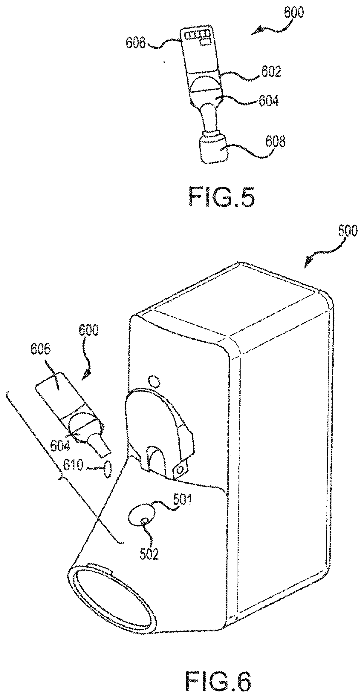
[0021] FIG. 5 illustrates another embodiment of a container for dispensing a unit volume of a liquid according to the invention.
[0022] FIG. 6 illustrates the container of FIG. 5 when dispensing a unit volume of liquid into the dispensing apparatus of FIG. 4.
[0023] FIG. 7 illustrates an embodiment of an ampoule for dispensing a unit volume of a liquid according to the invention.
[0024] FIG. 8 illustrates the ampoule of FIG. 7 with an end removed.
[0025] FIG. 9 illustrates the ampoule of FIG. 8 with the top end also removed and being deposited into a dispensing apparatus.
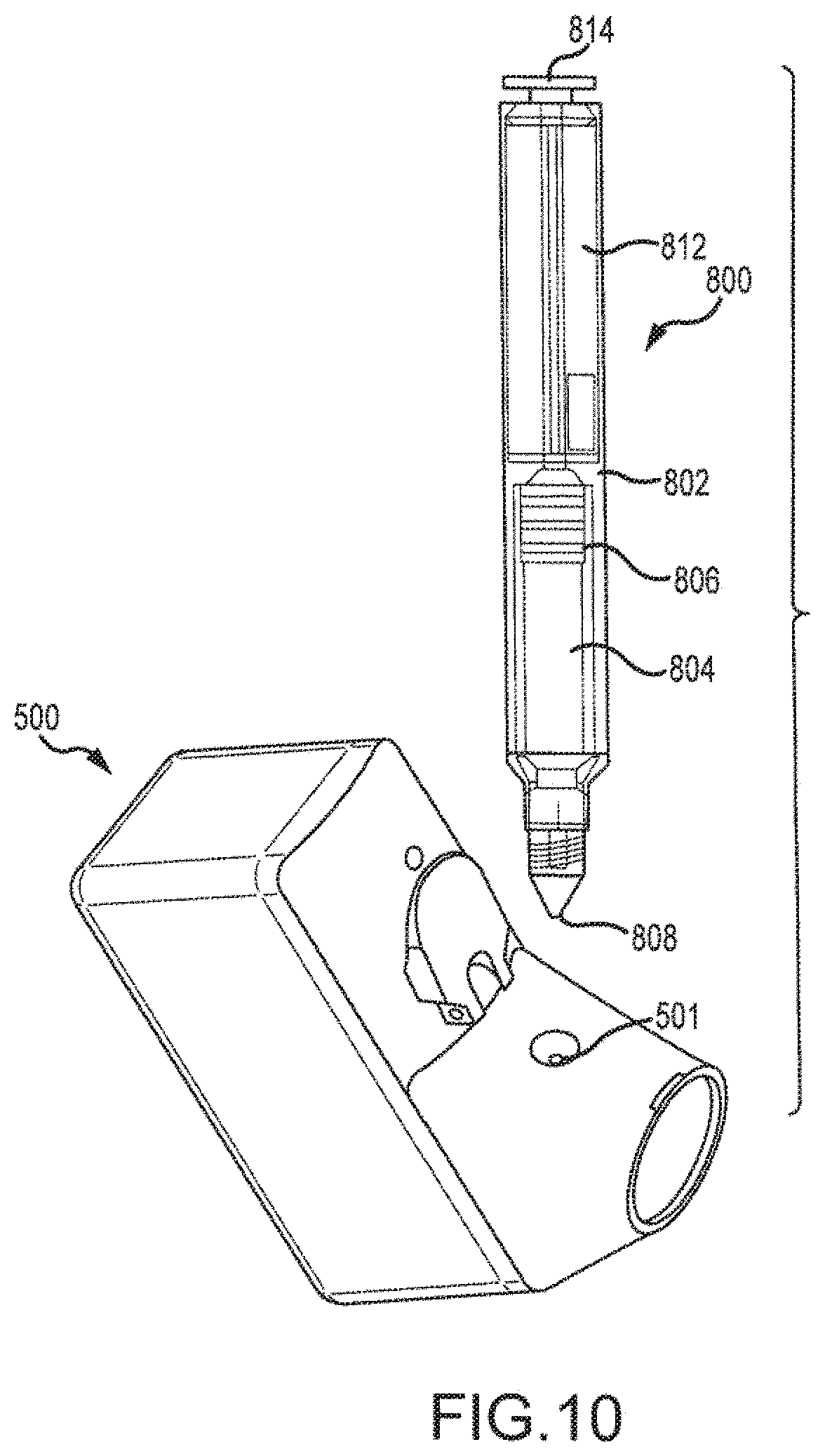
[0026] FIG. 10 illustrates another embodiment of a container for dispensing a unit volume of a liquid into the dispensing apparatus of FIG. 4.
DETAILED DESCRIPTION OF THE INVENTION
[0027] Certain aspects of the invention describe an aerosolizing apparatus comprising a housing defining a dispensing outlet, a vibratable membrane having a front face exposed at the outlet and a rear face for receiving a liquid to be dispensed, and a vibrating mechanism connected to the housing and operable to vibrate the membrane to dispense aerosol of the liquid through the membrane. A liquid delivery system is used to deliver a metered quantity of the liquid from to the rear face of the membrane. In this way, a metered quantity of liquid is dispensable at the outlet by operating the vibrating mechanism for an operating period sufficient to completely aerosolize the metered quantity of the rear face.
[0028] An advantage of such an apparatus is that it facilitates the dispensing of substantially all of the liquid coming into contact with the rear face of the membrane as a single dose, especially when the metered dose is relatively small in volume. By dispensing the entire dose, the membrane is essentially free of liquid from one dose to the next. In this way, it is thereby possible to avoid contact between liquid and ambient air during periods of non-use between successive uses. For pharmaceutical preparations this is particularly important since it may obviate the need for the use of preservatives in the liquid and avoids evaporative losses. For example, various preservative free insulin formulations that may be used include those described in copending U.S. application Ser. No. 13/004,662, entitled "Preservative Free Insulin Formulations and Systems and Methods for Aerosolizing" and filed on the same date as the present application, previously incorporated by reference.
[0029] The liquid supply system in one embodiment may comprise a deformable thin-wall blister which contains a pharmaceutical agent. The supply system further comprises a mechanical press configured to deform the thin-walled blister such that a single, preservative free unit dose is delivered. The press mechanism is provided with a dispensing station provided with a piercing needle operable to pierce the blister and release its content upon actuation.
[0030] In one aspect, the needle has two ends, with the first end protruding from the surface of the dispensing station and a second end extending to rear face of the aerosol generator. In use the blister is seated in the dispensing station and the press mechanism forces the blister toward the needle which pierces through the thin wall. In this way, the needle provides a conduit for moving the liquid from the blister to the rear face of the vibratable membrane. When the press mechanism is released the blister expands and returns to its natural position. This expansion creates a suction action which removes the liquid from the needle and prevents dry out and clogging.
[0031] In a further aspect, the blister has a bellows shaped geometry which can elastically expand and compress. The term elastically expand and compress includes when the blister is fully compressed the internal stresses are still within the elastic range of the material in use, thus, the blister can return to its natural position when the press mechanism is released. In one particular aspect, the pharmaceutical agent fills at least 80% the internal volume of the blister and more preferably more than 90% of the volume. This prevents movement of liquid which in some cases may cause aggregation of the composition.
[0032] Conveniently, the end of the needle may be positioned in close proximity to the rear face of the vibratable membrane. Further, the housing may define a duct communicating between an air inlet and an outlet port. The dispensing outlet is located in the duct intermediate the air inlet and the outlet port such that the front face of the membrane is exposed to air within the duct. The outlet port may be a mouthpiece for inhalation or an adapter for nasal use.
[0033] Such an arrangement is particularly useful in the administration of inhaled pharmaceutical liquid products where it is required that a fine aerosol of liquid be entrained in an inhaled air flow passing through the mouthpiece. One example of such a liquid is an insulin composition.
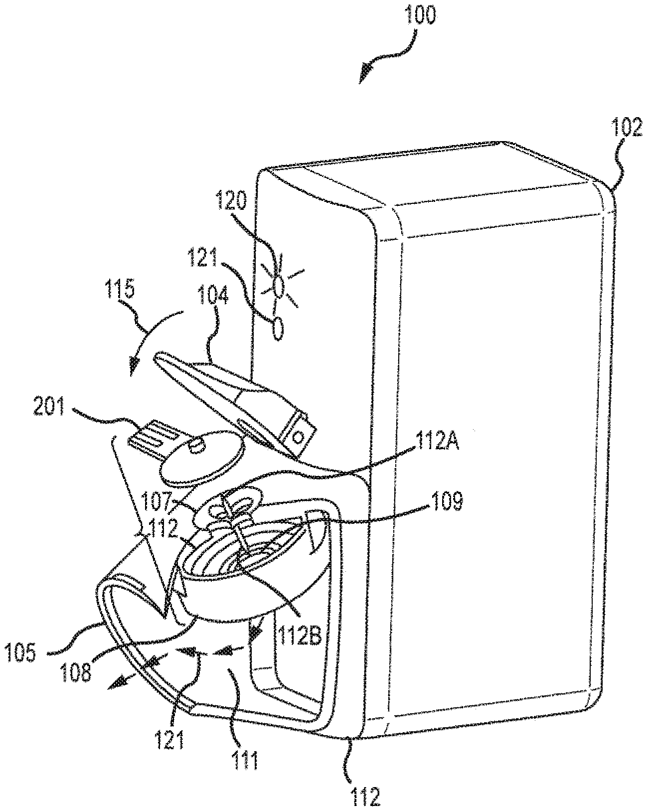
[0034] Referring now to FIG. 1, one embodiment of an inhaler will be described. FIG. 1 illustrates a partially cut-away view of the single-dose-inhaler 100 and a unit dose blister 201 package for supplying a metered quantity of insulin to the inhaler. Inhaler 100 comprises two subassemblies 102 and 112. The first subassembly 102 defines a compartment for the electronic circuitry and the batteries, and the second subassembly 112 defines a housing with a dispensing outlet 105 and contains a vibratable membrane aerosol generator 108 and a dispensing mechanism 104. Aerosol generator 108 has a front face exposed at the outlet duct 111 and a rear face 109 contacted in use by liquid to be dispensed. Aerosol generator 108 is connected to the housing of subassembly 112 and is operable to dispense the active pharmaceutical agent as an aerosol through the mouthpiece 105. Exemplary aerosol generators that may be used are also described in U.S. Pat. Nos. 5,164,740; 6,629,646; 6,926,208; 7,108,197; 5,938,117; 6,540,153; 6,540,154; 7,040,549; 6,921,020; 7,083,112; 7,628,339; 5,586,550; 5,758,637; 6,085,740; 6,467,476; 6,640,804; 7,174,888; 6,014,970; 6,205,999; 6,755,189; 6,427,682; 6,814,071; 7,066,398; 6,978,941; 7,100,600; 7,032,590; 7,195,011, incorporated herein by reference. These references describe exemplary aerosol generators, ways to manufacture such aerosol generators and ways to supply liquid to aerosol generators, and are incorporated by reference for at least these features. The aerosol generators may comprise vibratable membranes having tapered aperture with a size in the range from about 3 .mu.m to about 8 .mu.m, preferably from about 3 .mu.m to about 6 .mu.m, and in some cases around 4 .mu.m. The membrane may be domed shaped and be vibrated by an annular piezoelectric element that circumscribes the apertures. The diameter of the membrane may be in the range from about 5 mm to about 8 mm. The membrane may also have a thickness in the range from about 50 microns to about 70 microns. Typically, the membrane will be vibrated at a frequency in the range from about 50 kHz to about 150 kHz.
[0035] Each time the dispensing system is operated it delivers a metered quantity of the liquid from the unit dose blister 201 to the rear face 109 of the aerosol generator. Hence, for each use a metered quantity of aerosolized pharmaceutical agent is dispensed at the mouthpiece outlet 105 by operation of the aerosol generator.
[0036] The blister 201 contains a predetermined volume of an active pharmaceutical agent to be dispensed. In one embodiment the blister 201 contains about 80 to about 120 micro-liters of insulin. The lower limit is typically at least about 15 micro-liters and the upper limit is typically about 1,000 micro-liters to about 2,000 micro-liters. One particularly useful range is about 80 micro-liters to about 120 micro-liters in a concentration of about 100 insulin units/ml or greater, and more preferably between about 200-800 units/ml, and in some cases as high as 2,500 units/ml. Blister 201 is made of thin-walled deformable material. Due to sensitivity of insulin to mechanical agitation, the blister 201 is filled-up to nearly its entire volume. Specifically, more than 80% of the volume is filled with insulin.
[0037] Inhaler 100 further includes a dispensing station configured to dispense the content of the blister 201 to the aerosol generator 108. The dispensing station includes a swivel arm member 104 and a blister seat 107. The blister seat 107 has a concave shape which may radially match the convex shape of the blister 201. The blister seat 107 further includes a hypodermic needle 112 which establishes a fluid passage from the blister to the vibrating aerosol generator 108. The needle 112 has two sections. The first section 112A extends from the dispensing seat and protrudes outwardly perpendicularly to blister seat 107. The second end 112B extends inwardly toward the aerosol generator 108 and is positioned in closed proximity to rear side of the vibrating membrane of aerosol generator 108. Typically, second end 112B will be less than 5 mm and more preferably less than 2 mm from the vibrating membrane of the aerosol generator 108. The hypodermic needle 112 may be made of stainless steel alloy type 316 with a gage size ranging from 22 gage to 26 gage. The first section 112A has a sharp slanted piercing tip. In use, blister 201 is placed upon the concave seat 107 and then the swivel arm 104 is rotated counter clockwise in the direction of arrow 115.
[0038] Conveniently, the force upon the swivel arm 104 may be applied by a thumb against the curved portion of the arm 104. This action forces the blister toward the piercing tip of the needle 112A which subsequently pierces the blister 201 and squeezes its content via the needle 112 through the outlet of the needle 112B and onto the aerosol generator 108. When the swivel arm 104 is fully depressed, the entire dose is delivered to the vibrating membrane of the aerosol generator 108.
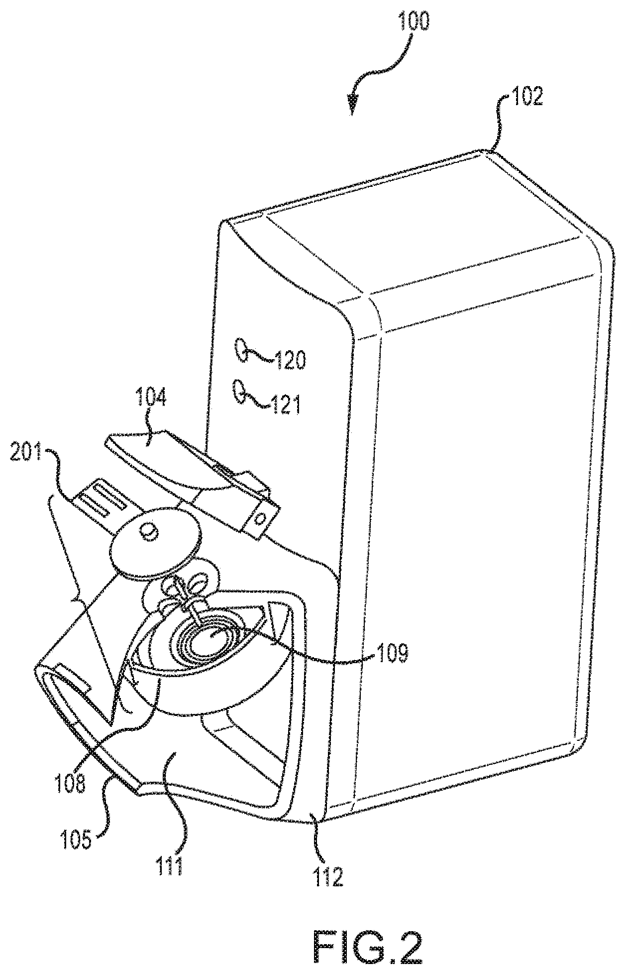
[0039] FIG. 2 illustrates the vibrating membrane 109 of the aerosol generator 108 in greater detail. When the content of the blister 201 is fully dispensed an indicator light 120 starts to blink signaling to the patient that the inhaler 100 is ready for use. At any time shortly thereafter the patient may inhale through the mouthpiece 105. Patient inhalation is detected by a flow sensor which in turn activates the aerosol generator 108 to produce aerosol particles into the duct 111. Aerosol is entrained in the inhalation air flow in the direction shown by arrows 121 and flow via the respiratory system to the lungs of the patient. When the entire dose is aerosolized, which may take one or morel breaths, the "end-of-dose" indicator light 121 lights a second time to signal the patient that the entire dose has been delivered. Delivery of the entire dose is obtained when at least about 95% of the dose is delivered, more preferably 98% and most preferably when more than 99% of the dose is delivered. In one embodiment, the opening funnel to the aerosol generator is sufficiently large such that the liquid delivery to the aerosol generator is delivered in its entirety. To receive the dose, the patient may take several inhalations or a single inhalation depending on the volume delivered to the mesh and the patient's breathing capacity. Each inhalation should be a deep breath to assure that the aerosol reaches deeply to the lungs.
[0040] When the end-of-dose indicator light 120 is actuated following inhalation of the contents of blister 201, the empty blister may be removed and discarded. When the thumb pressure on the swivel arm 104 is release the blister expands to its original shape. Expansion creates a vacuum inside the blister 201 which draws back any adhered fluid from the needle back to the blister, thereby leaving the interior of the needle dry to prevent material dry-out and clogging. To further prevent possible bacterial contamination the internal and/or the external surfaces of the needle, needle 112 may be coated with silver, a silver based coating or the like.
[0041] FIG. 3 illustrates the concave seat 107 of the dispensing station in greater detail. Seat 107 is provided with holes 117 which provides access to the interior of the inhaler in the vicinity of the aerosol generator 108. This permits cleaning solvents and rinsing water to be supplied to the aerosol generator 108.
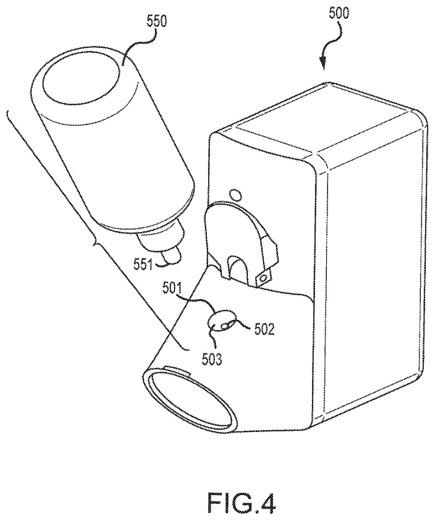
[0042] FIG. 4 provides an alternative delivery system for an inhaler 500 which utilizes a preservative free dispenser 550 and a nozzle 551 to dispense a volume of a preservative free pharmaceutical agent to the aerosol generator via an opening 501. Inhaler 500 can be constructed in a manner similar to inhaler 100 and may include a similar aerosol generator. Opening 501 has a funnel shape which tapers down to a small opening 502, thus forming a slope 503. Dispenser 550 is a uniform drop, preservative free dispenser which upon activation displaces a single drop through the tip of its nozzle 551. Preferably, the drop volume is smaller than about 200 micro-liters. A dose is dispensed by squeezing container 550 in a direction perpendicular to its longitudinal axis. Upon each actuation, a single drop of a fixed volume is displaced through the nozzle 551.
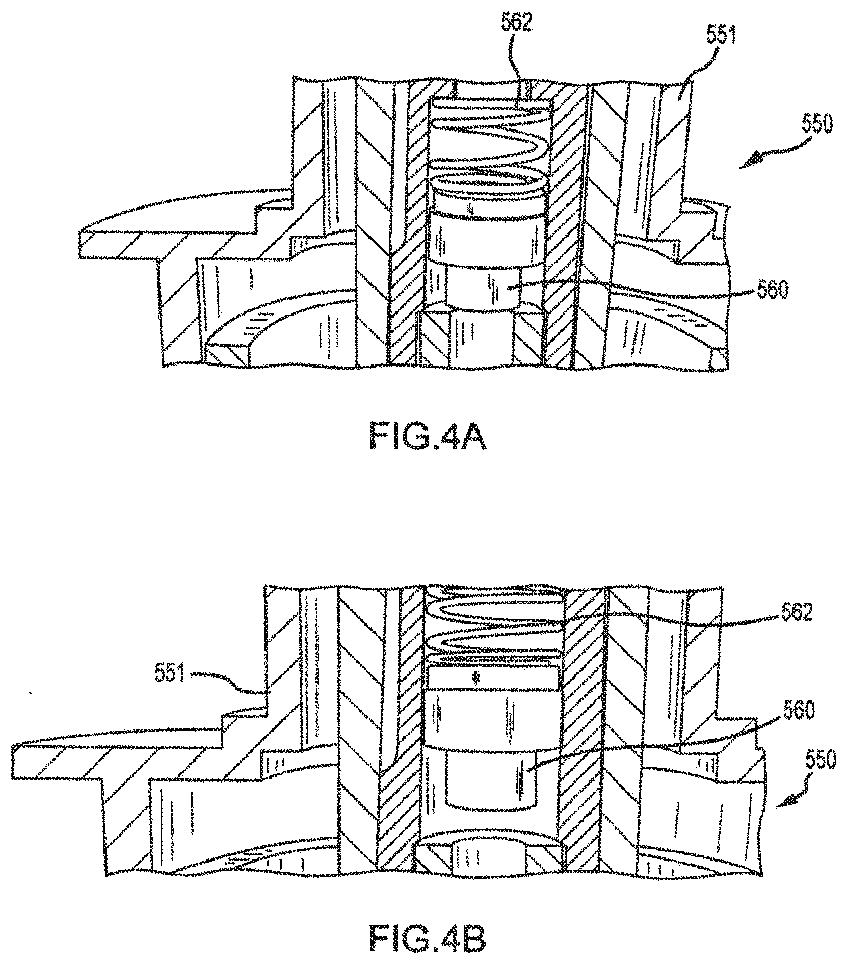
[0043] One exemplary dispenser is the Aptar OSD dispenser, developed by Ing. Erich Pfeiffer GmbH. Such a container is constructed of a squeeze bottle that is squeeze to dispense a droplet. When released, the nozzle prevents microbiological contaminants from entering into the remaining liquid. This is accomplished through a tip seal (see, for example, tip seal 560 of FIGS. 4A and 4B) that prevents back flow of liquid into the container. As shown in FIG. 4A, the tip sealing mechanism includes a spring 562 that keeps the tip seal 560 in place in a normally closed position. When squeezing the bottle, liquid passes between the seal 560 and a cap until sufficient pressure is created to overcome the force of the spring 562 (see FIG. 4B). In this way, a single droplet can be dispensed. After dispensing, the tip seal again closes to prevent liquids from moving back into the container. To relieve the accumulating vacuum within the bottle, a small hole is included in the side of the container to allow air into the spring chamber. Droplet size can be controlled based on several factors including top size and the viscosity of the liquid.
[0044] In use, nozzle 551 is aligned with the opening 501 such that the drop is dispensed to the slope 503 and flows through the opening 502 to the aerosol generator. Preferably, the angle of slope 503 is greater than about 30 degrees relative to the axis of the opening 502. The diameter of opening 501 is about 10 mm to about 15 mm and the diameter of opening 502 is at least about 5 mm. The pharmaceutical fluid in the preservative free dispenser 550 may be contained in a collapsible sack to prevent excessive agitation and which may damaged by mechanical sloshing. For example, proteins, such as insulin, may be sensitive to mechanical agitation. Use of a collapsible sack may limit undesirable agitation.
[0045] In another alternative embodiment, instead of using a container of the type described in FIG. 5, a container 600 could be used. Container 600 comprises a blister 602 manufactured using a blow-fill-seal process. Container 600 is similar to the container 201 of FIG. 1 in that when the blister 602 is squeezed a unit dosage amount is delivered.
[0046] Blister 602 comprises a squeezable body 604 having a tab 606 and a twist off top 608. Body 604 is sized to hold a unit dosage of liquid, and tab 66 may include various types of identifying information, such as the lot number, date, and the like. Twist off top 608 provides a easy way to open blister 602 so that the liquid can be dispensed.
[0047] Referring also to FIG. 6, use of blister 602 in supplying a unit dose of liquid to inhaler 500 will be described. When ready to receive a treatment, a user takes blister 602 and twists off top 608. Typically, blister 602 will be held upright so that no liquid escapes. In some cases, the opening formed when top 608 is removed may be sized small enough to hinder liquid from escaping. Blister 602 is moved over opening 501 and body 604 is squeezed to expel the complete volume of liquid 610 into opening 501 where the liquid drains through opening 503 and to the aerosolizer. In this way, blister 602 functions as a hand squeezable, single use container for a preservative free solution. Use of a blow-fill-seal process is particularly advantageous in that the blister 602 can be manufactured at low cost while still allowing the storage of a preservative free solution. Also, the metering process is simple, requiring only the removal of the top and squeezing of the blister.
[0048] FIG. 7 illustrates an embodiment of an ampoule 700 for dispensing a unit volume of a liquid to be aerosolized. Ampoule 700 comprises an elongate body 702 defining a capillary that hold a unit volume of liquid 704. Ampoule 700 further includes a top end 706 and a bottom end 708 that may be removed from body 702, such as by snapping them off. Body 702 may be constructed of a generally rigid material that has sufficient rigidity to permit the two ends to be easily snapped off.
[0049] When ready to dispense the liquid into an inhaler, top end 706 is removed as illustrated in FIG. 8. The surface tension in body 702 prevents leakage of any liquid 704 when ampoule 700 is inverted, such as when inserting ampoule 700 into an inhaler.
[0050] FIG. 9 illustrates the ampoule of FIG. 8 after being inserted into an inhaler 720. Inhaler 720 may be constructed in a manner similar to the other embodiments described herein an includes electronics 722 that are employed to control operation of an aerosol generator 724 having a vibratable mesh 726. Inhaler 720 includes an elongate opening 730 into which ampoule 700 is inserted after end 706 is removed. Once in place, end 708 is snapped off which allows liquid 704 to drain from ampoule 700 and onto the rear face of vibratable mesh 726 as illustrated in FIG. 9. As mesh 726 vibrates, the liquid is aerosolized and directed toward a mouthpiece 732 where the patient can inhale the medicament. Following aerosolization, ampoule 700 may be removed from inhaler 720 and discarded.
[0051] FIG. 10 illustrates another embodiment of a container 800 for dispensing a unit volume of a liquid into the dispensing apparatus 500 that was previously described in connection with FIG. 4. Container 800 comprises a container body 802 defining a reservoir 804 for holding a volume of liquid to be dispensed. A plunger 806 is employed to force liquid in reservoir 804 through a dispensing end 808 of container 800. Container 800 also includes a geared metering mechanism 812 that is rotated or "dialed" in order to control the extent of movement of plunger 806. Further, an actuator 814 is pressed to move the plunger 806 by the amount permitted by metering mechanism 812. In this way, a user can simply "dial a dose" of liquid using metering mechanism 812 and then press actuator 814 in order to dispense a metered amount of liquid into hole 501 where it will be supplied to the aerosolization mechanism.
[0052] Container 800 can be configured to be disposable or reusable. When reusable, reservoir 804 may comprise a cartridge that is inserted into the space defined by reservoir 804. Exemplary volume sizes may be about 1, 1.8 or 3 ml cartridges, which may be constructed of glass, LDPE or the like.
[0053] The invention has now been described in detail for purposes of clarity and understanding. However, it will be appreciated that certain changes and modifications may be practiced within the scope of the appended claims.
* * * * *
D00000
D00001
D00002
D00003
D00004
D00005
D00006
D00007
D00008
XML
uspto.report is an independent third-party trademark research tool that is not affiliated, endorsed, or sponsored by the United States Patent and Trademark Office (USPTO) or any other governmental organization. The information provided by uspto.report is based on publicly available data at the time of writing and is intended for informational purposes only.
While we strive to provide accurate and up-to-date information, we do not guarantee the accuracy, completeness, reliability, or suitability of the information displayed on this site. The use of this site is at your own risk. Any reliance you place on such information is therefore strictly at your own risk.
All official trademark data, including owner information, should be verified by visiting the official USPTO website at www.uspto.gov. This site is not intended to replace professional legal advice and should not be used as a substitute for consulting with a legal professional who is knowledgeable about trademark law.