Compressive Bump Cap
Blaxter, III; H. Vaughan ; et al.
U.S. patent application number 16/562719 was filed with the patent office on 2020-03-12 for compressive bump cap. The applicant listed for this patent is 2ND SKULL, INC.. Invention is credited to H. Vaughan Blaxter, III, Marvin Church, Michael Laskowski, Kevin M. Lynch.
| Application Number | 20200077730 16/562719 |
| Document ID | / |
| Family ID | 69718999 |
| Filed Date | 2020-03-12 |


| United States Patent Application | 20200077730 |
| Kind Code | A1 |
| Blaxter, III; H. Vaughan ; et al. | March 12, 2020 |
COMPRESSIVE BUMP CAP
Abstract
A compressive bump cap is provided which has an inner protection system. The compressive bump cap is stretchable between a relaxed configuration and an expanded configuration. The expanding configuration has a convex shape such that it can conform to a head of a wearer.
| Inventors: | Blaxter, III; H. Vaughan; (Pittsburgh, PA) ; Lynch; Kevin M.; (Pittsburgh, PA) ; Church; Marvin; (Apollo, PA) ; Laskowski; Michael; (Pittsburgh, PA) | ||||||||||
| Applicant: |
|
||||||||||
|---|---|---|---|---|---|---|---|---|---|---|---|
| Family ID: | 69718999 | ||||||||||
| Appl. No.: | 16/562719 | ||||||||||
| Filed: | September 6, 2019 |
Related U.S. Patent Documents
| Application Number | Filing Date | Patent Number | ||
|---|---|---|---|---|
| 62728375 | Sep 7, 2018 | |||
| Current U.S. Class: | 1/1 |
| Current CPC Class: | A42B 1/08 20130101 |
| International Class: | A42B 1/08 20060101 A42B001/08 |
Claims
1. A compressive bump cap, comprising: a multi-layer sidewall, wherein the multi-layer sidewall forms a dome, wherein the dome defines a circular opening for a head of a wearer, and wherein the multi-layered sidewall comprises: an inner stretchable fabric layer; an outer stretchable fabric layer; and an inner protection system positioned in a pocket defined by the inner stretchable fabric layer and the outer stretchable fabric layer, wherein the inner protection system comprises a rigid layer and a padding layer; and wherein the inner stretchable fabric layer and the outer stretchable fabric layer are expandable from a relaxed state to an expanded state.
2. The compressive bump cap of claim 1, wherein the rigid layer is immediately adjacent to the outer stretchable fabric layer and the padding layer is immediately adjacent to the inner stretchable fabric layer.
3. The compressive bump cap of claim 1, wherein the rigid layer comprises a molded plastic shell.
4. The compressive bump cap of claim 1, wherein the padding layer is non-removably coupled to the rigid layer.
5. The compressive bump cap of claim 1, wherein the padding layer is removably coupled to the rigid layer.
6. The compressive bump cap of claim 1, wherein the inner protection system is non-removably positioned in the pocket defined by the inner stretchable fabric layer and the outer stretchable fabric layer.
7. The compressive bump cap of claim 6, wherein the rigid layer is adhered to an inner surface of the outer stretchable fabric layer.
8. The compressive bump cap of claim 1, wherein the inner protection system is removably positioned in the pocket defined by the inner stretchable fabric layer and the outer stretchable fabric layer.
9. The compressive bump cap of claim 1, wherein the inner stretchable fabric layer is stitched to the outer stretchable fabric layer to define the pocket.
10. The compressive bump cap of claim 1, further comprising an elastic member positioned proximate to and encircling the circular opening.
11. The compressive bump cap of claim 1, wherein at least a portion of the inner stretchable fabric layer is mesh.
12. The compressive bump cap of claim 1, wherein at least a portion of the outer stretchable fabric layer is mesh.
13. The compressive bump cap of claim 1, wherein each of the inner stretchable fabric layer and the outer stretchable fabric layer comprise a plurality of individual panels.
14. A compressive bump cap, comprising: a multi-layer sidewall, wherein the multi-layer sidewall forms a dome, wherein the dome defines a circular opening for a head of a wearer, and wherein the multi-layered sidewall comprises: an inner stretchable fabric layer; an outer stretchable fabric layer, wherein the outer stretchable fabric layer and the inner stretchable fabric layer collectively define a pocket, and wherein the inner stretchable fabric layer and the outer stretchable fabric layer are expandable from a relaxed state to an expanded state; a rigid layer positioned with the pocket; and a padding layer positioned within the pocket between the rigid layer and the inner stretchable fabric layer.
15. The compressive bump cap of claim 14, wherein the rigid layer is coupled to the padding layer.
16. The compressive bump cap of claim 15, wherein the rigid layer and the padding layer are removable from the pocket.
17. A compressive bump cap, comprising: a multi-layer sidewall, wherein the multi-layer sidewall forms a dome, wherein the dome defines a circular opening for a head of a wearer, and wherein the multi-layered sidewalls comprises: an inner stretchable fabric layer; an outer stretchable fabric layer; and an inner protection system removably non-removably positioned in a pocket defined by the inner stretchable fabric layer and the outer stretchable fabric layer, wherein the inner protection system comprises a rigid layer coupled to a padding layer; and wherein the inner stretchable fabric layer and the outer stretchable fabric layer are expandable from a relaxed state to an expanded state.
18. The compressive bump cap of claim 17, wherein the rigid layer comprises a molded shell.
19. The compressive bump cap of claim 18, wherein the padding layer comprises pliable rate-dependent material.
20. The compressive bump cap of claim 17, wherein each of the inner stretchable fabric layer and the outer stretchable fabric layer comprise a plurality of triangular individual panels.
Description
CROSS-REFERENCE TO RELATED APPLICATION
[0001] This application claims the benefit of U.S. application No. 62/728,375, filed Sep. 7, 2018, and entitled COMPRESSIVE BUMP CAP, the disclosure of which is incorporated herein by reference in its entirety.
TECHNICAL FIELD
[0002] The systems and methods described below relate generally to the field of head protection. More particularly, the systems and methods relate to compressive bump caps that help protect wearers from minor cuts, bumps, and bruises due to contact with stationary objects.
BACKGROUND
[0003] Bump caps are a form of head protection that can be worn in a number of different environments in which head protection may be desired, but is not necessarily required. A person in such an environment may not be required to wear a traditional hardhat, but still desire to be provided with a certain amount of protection from lacerations and abrasions caused by minor bumps to the head. Conventionally, bump caps are not designed to protect against falling objects, but instead are designed to protect against light injuries for workers in various settings, such as food industry workers, mechanics, or trucker drivers, for example.
BRIEF DESCRIPTION OF THE DRAWINGS
[0004] The present disclosure will be more readily understood from a detailed description of some example embodiments taken in conjunction with the following figures:
[0005] FIG. 1 shows an example compressive bump cap in accordance with one non-limiting embodiment.
[0006] FIG. 2 depicts a partial cutaway view of an example compressive bump cap in accordance with one non-limiting embodiment.
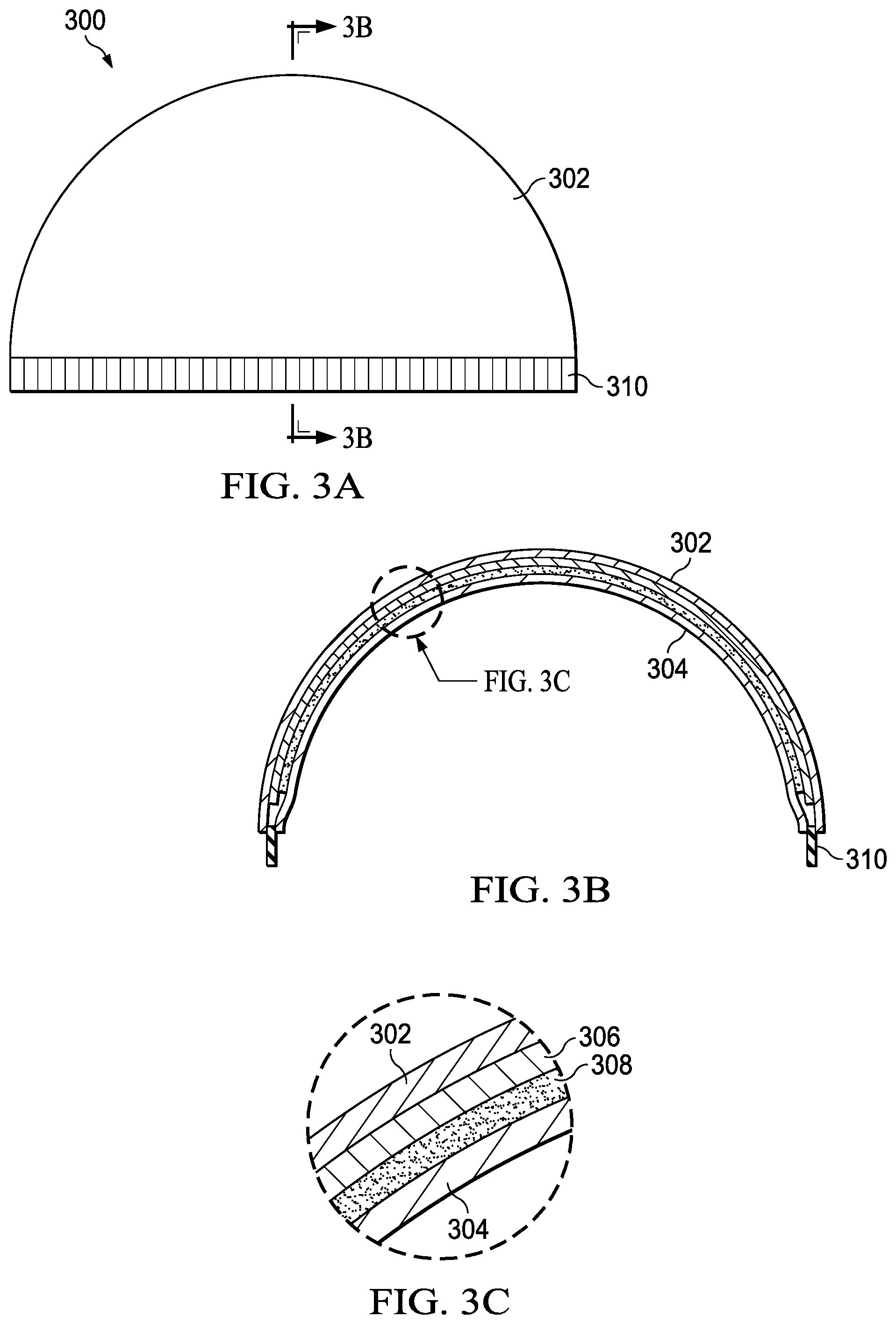
[0007] FIGS. 3A-C depicts an example compressive bump cap, with FIG. 3B showing a cross-sectional view of FIG. 3A and FIG. 3C showing an enlarged view of FIG. 3B.
[0008] FIG. 4 depicts the compressive bump cap of FIGS. 3A-3C being positioned on the head of a wearer and stretching from a relaxed configuration to an expanded configuration.
[0009] FIG. 5 shows an exploded view of a compressive bump cap in accordance with one non-limiting embodiment.
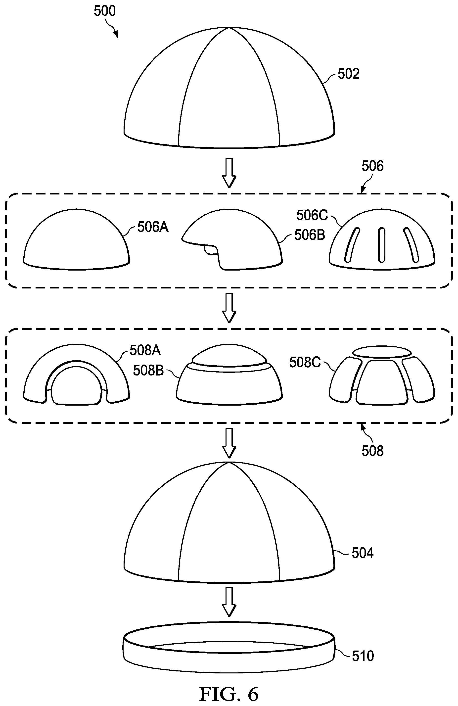
[0010] FIG. 6 shows an exploded view of another compressive bump cap in accordance with one non-limiting embodiment.
[0011] FIG. 7 depicts one example of a padding layer in a flat, unattached state.
DETAILED DESCRIPTION
[0012] Various non-limiting embodiments of the present disclosure will now be described to provide an overall understanding of the principles of the structure, function, and use of the compressive bump caps disclosed herein. One or more examples of these non-limiting embodiments are illustrated in the accompanying drawings. Those of ordinary skill in the art will understand that systems and methods specifically described herein and illustrated in the accompanying drawings are non-limiting embodiments. The features illustrated or described in connection with one non-limiting embodiment may be combined with the features of other non-limiting embodiments. Such modifications and variations are intended to be included within the scope of the present disclosure.
[0013] The presently disclosed embodiments are generally directed to compressive bump caps, compressive bump cap systems, methods of using a compressive bump cap, and methods of manufacturing compressive bump caps. Such systems and methods may be implemented in a wide variety of contexts and applications. In one example embodiment, the compressive bump cap is configured such that it can be retained on a user's head without the use of a securing strap, such as a chinstrap. The compressive bump caps can be constructed with one or more layers, sections, or pockets of impact absorbing or impact dissipating materials, referred to generally herein as padding. The particular type of padding can vary based on a variety of factors, such as style of compressive bump cap, industrial application, type of user, size of compressive bump cap, and so forth.
[0014] As described in more detail below, in some embodiments, the compressive bump cap can have multiple layers, including an inner layer, a padding layer, a rigid layer, and an outer layer. Other embodiments of compressive bump caps can have more than four layers or less than four layers. The compressive bump cap can also have breathable characteristics, sweat wicking characteristics, or other comfort related characteristics, such as vents, mesh, or perforations. The compressive bump cap can have water resistant or water repellant qualities. In some embodiments, the compressive bump cap can include an anti-bacterial agent, anti-microbial agent, anti-odor agent, or other deodorizing or sanitizing compounds. In some embodiments, the compressive bump cap is configured to provide protection against ultraviolet rays using any suitable techniques, such as chemical treatments, construction techniques, materials, and so forth.
[0015] As is to be appreciated, the compressive bump cap described herein can be sized to accommodate different sizes of users. In one example embodiment, a "one size fits all" compressive bump cap is sized to most adult wearers. In some embodiments, compressive bump caps can be manufactured in different sizes (small, medium, large, x-large, and so forth).
[0016] Reference throughout the specification to "various embodiments," "some embodiments," "one embodiment," "some example embodiments," "one example embodiment," or "an embodiment" means that a particular feature, structure, or characteristic described in connection with the embodiment is included in at least one embodiment. Thus, appearances of the phrases "in various embodiments," "in some embodiments," "in one embodiment," "some example embodiments," "one example embodiment, or "in an embodiment" in places throughout the specification are not necessarily all referring to the same embodiment. Furthermore, the particular features, structures or characteristics may be combined in any suitable manner in one or more embodiments.
[0017] Referring now to FIG. 1, a compressive bump cap 100 in accordance with one non-limiting embodiment is shown. As described in more detail below, the compressive bump cap 100 can include a plurality of layers which includes a padding layer and a rigid layer, sometimes referred to as a shell. Through the use of stretching fabrics and/or elastics, the compressive bump cap 100 can be configured to be generally compressive such that its position on a head of a wearer can be maintained without the use of chin strap. In the illustrated embodiment, the compressive bump cap 100 has an outer layer 102 that is coupled to an elastic member 110. The elastic member 110 can be a band that generally encircles an opening at a lower periphery of the compressive bump cap 100. The elastic member 110 can aid in securing the compressive bump cap 100 to a head of a wearer and maintaining its relative placement. The elastic member 110 may encircle the entire compressive bump cap 100 (as shown) or may be limited to certain portions of the compressive bump cap, such as the front and/or rear. The elastic member 110 can comprise, for example, an elastic band or cord positioned in a hem. As is to be appreciated, the particular configuration of the compressive bump cap 100 can be based on, for example, the operational environment of the person wearing the cap. Some embodiments may include a brim. Some embodiments may include vents to aid in heat dissipation. Some embodiments may include one or more thermal layers to aid in heat retention.
[0018] It is noted that while the compressive bump cap 100 depicts an elastic member around the lower periphery, such elastic members are not necessary for some configurations. Instead, the compressive bump cap can have compressive qualities or characteristics that maintain the compressive bump cap on the wearer's head. In other words, various layers of the compressive bump cap can be manufactured from stretchable materials that allow the compressive bump cap to stretch when placed on the head of a user and contract when removed from the head of a user. Further as described in more detail below, the compressive bump cap 100 can include and internal rigid shell that is positioned to provide head protection for the wearer.
[0019] Referring now to FIG. 2, a partial cutaway view of an example compressive bump cap 200 is shown. As shown, a sidewall of the compressive bump cap 200 is comprised of a plurality of individual layers. Adjacent layers may or may not be attached to each other. In the illustrated embodiment, the compressive bump cap 200 has an outer fabric layer 202 and an inner fabric layer 204. These two layers can be stitched or otherwise coupled together to define a pocket, or plurality of pockets. Placed between the fabric layers 202, 204 can be a rigid layer 206 and a padding layer 208. The rigid layer 206 can be, for example, a pre-formed shell that is generally hemispherical in shape. In some embodiments, the padding layer 208 is permanently attached to the rigid layer 206 via adhesive or other suitable technique. In some embodiments, the padding layer 208 is removably attached to the rigid layer 206 via hook and loop fasteners or other suitable techniques. In some embodiments, the padding layer 208 and the rigid layer 206 can collectively form an inner protection system of the compressive bump cap 200.
[0020] The padding layer 208 and the rigid layer 206 can be disconnected from both of the fabric layers 202, 204, such that the inner protection system is positioned within the pocket defined by the fabric layers 202, 204, but is generally free-floating therebetween. In other embodiments, however, one or both of the fabric layers 202, 204 are coupled to rigid layer 206, the padding layer 208, or both the rigid layer 206 and the padding layer 208. Similar to FIG. 1, the compressive bump cap 200 can also have an elastic member 210 that encircles the head-sized opening. As shown each of the fabric layers 202, 204 can be coupled to the elastic member 210, such as through stitching.
[0021] When the compressive bump cap 200 is placed on the head of a wearer, various components can stretch to generally conform to the shape of the wearer's head. Accordingly, the compressive bump cap 200 can stretch to a convex-shaped configuration, which may be referred to as hemispherical, when being worn by a user. In its stretched configuration, the compressive bump cap 200 delivers a compressive force to the wearer's head in order to substantially maintain the position of the compressive bump cap 200 relative to the wearer's head. It is noted that certain components of the compressive bump cap 200 can be mesh, or at least comprise one or more portions that are mesh or otherwise provide air flow to the wear.
[0022] Referring now to FIGS. 3A-3C, a compressive bump cap 300 in accordance with one non-limiting embodiment is shown. FIG. 3A shows a side view of the compressive bump cap 300 which has an elastic member 310 positioned around its lower periphery. The elastic member 310 can be an elastic band positioned inside a hem, for example. In some embodiments, an elastic member can be fed through hoops or other retention members. FIG. 3B shows a cross-sectional view of the compressive bump cap 300 taken along line 3B-3B of FIG. 3A. FIG. 3C shows an enlarged view of the encircled area of FIG. 3B and illustrates various layers of the compressive bump cap 300. As shown in FIGS. 3A-3C the compressive bump cap 300 of the illustrated embodiment comprises an outer layer 302, a rigid layer 306, a padding layer 308, and an inner layer 304. A layer of adhesive may be applied between the rigid layer 306 and the padding layer 308.
[0023] The padding layer utilized by compressive bump caps in accordance with the present disclosure can be comprised of any suitable material that provides the desirable characteristics and response to impact. For example, the padding layer can comprise one or more of the following materials: thermoplastic polyurethane (available, for example, from Skydex Technologies), military-grade materials, impact absorbing silicone, D30.RTM. impact absorbing material, impact gel, wovens, non-wovens, cotton, elastomers, IMPAXX.RTM. energy-absorbing foam (available from Dow Automotive), DEFLEXION shock absorbing material (available from Dow Corning), styrofoam, polymer gels, general shock absorbing elastometers, visco-elastic polymers, PORON.RTM. XRD impact protection (available from Rogers Corporation), Sorbothane.RTM. (available from Sorbothane Inc.), Neoprene (available from DuPont), Ethyl Vinyl Acetate, impact-dispersing gels, foams, rubbers, and so forth. The padding layer can be breathable and/or generally porous to provide ventilation. In some embodiments, the padding layer is a mesh material that aids in the breathability of the associated compressive bump cap. The padding layer can be attached to one or more layers (such as the rigid layer 306 and the inner layer 304 of FIG. 3C, for example). In some embodiments, the padding layer can be generally disconnected and "floating" between the layers. In some embodiments, the padding layer is attached to an elastic member or other portions of the compressive bump cap.
[0024] In some embodiments, padding layers in accordance with the present systems and methods can comprise a rate dependent material, such as a rate dependent low density foam material. Examples of suitable low density foams include polyester and polyether polyurethane foams. In some embodiments, such foams to have a density ranging from about 5 to about 35 pounds per cubic foot (pcf), more particularly from about 10 to about 30 pcf, and more particularly still from about 15 to about 25 pcf. PORON.RTM. and PORON XRD.RTM. are available from Rogers Corporation, which are open cell, microcellular polyurethane foams, is an example of one suitable rate dependent foam. However, in order to provide impact resistance, the padding layer can be any suitable energy absorbing or rate dependent materials. As such, other rate dependent foams or other types of materials can be used without departing from the scope of the present disclosure.
[0025] The material can be, for example, and without limitation, polyester, nylon, spandex, ELASTENE (available from Dow Chemical), cotton, materials that glow in the dark or are fluorescent, and so forth. Either of the inner or outer layers can also be of a mesh or otherwise porous material. In some embodiments, the inner and/or outer layers can be a blend of a variety of materials, such as a spandex/polyester blend. In some embodiments, the compressive bump cap is water proof, water resistant, or water repellant. Other durable materials can be used for the outer layer of any embodiment, including knit, woven and nonwoven fabrics, leather, vinyl or any other suitable material. In some instances, it can be desirable to use materials for the layer than are somewhat elastic; therefore, stretchable fabrics, such as spandex fabrics, can be desirable. Such materials can help provide compressive forces to maintain placement of compressive bump cap on a wearer's head without the need for a chin strap, for example.
[0026] The rigid layer utilized by compressive bump caps in accordance with the present disclosure can be comprised of any suitable material that provides the desirable characteristics and response to impact. The rigid layer can be, for example, a molded plastic, Styrofoam, thermoplastic, carbon fiber, or other suitable rigid or semi-rigid materials.
[0027] Various compressive bump caps in accordance with the systems and methods described herein can be manufactured with or otherwise include various coatings, agents, or treatments to provide anti-microbial or anti-bacterial properties. Some embodiments, for example, can utilize Microban.RTM. offered by Microban International, Ltd. for antibacterial protection. In some embodiments, the padding layer comprises antimicrobial agents and one or more other fabric layers of the compressive bump cap also treated with antimicrobial agents. Antimicrobial protection for the fabric layers can be in the form of a chemical coating applied to the fabric, for example. Generally, antimicrobial technologies combat odor by fighting bacteria resulting in fresher smell for longer and minimizing the frequency of laundering or washing. Any suitable technique can be used to provide compressive bump caps with antimicrobial properties. In one embodiment, for example, AEGIS Microbe Shield.RTM. offered by DOW Corning Corp. is utilized. Other examples of antimicrobial agents include SILVADUR.RTM. offered by The Dow Chemical Company is utilized, Smart Silver offered by NanoHorizons, Inc., and HealthGuard.RTM. Premium Protection offered by HealthGuard.
[0028] In some embodiments, a compressive bump cap, or at least various components of a compressive bump cap are configured to provide moisture wicking properties. Generally, moisture wicking translates into sweat management, which works by removing perspiration from the skin in an attempt to cool the wearer. Any suitable moisture wicking can be used. In one embodiment, a topical application of a moisture wicking treatment to a fabric of the compressive bump cap is utilized. The topical treatment is applied to give the compressive bump cap the ability to absorb sweat. The hydrophilic (water-absorbing) finish or treatment generally allows the compressive bump cap to absorb residue, while the hydrophobic (water-repellent) fibers of the compressive bump cap help it to dry fast, keeping the wearer more comfortable. In one embodiment, the blend of fiber is used to deliver moisture wicking properties by combining a blend of both hydrophobic (such as polyester) with hydrophilic fibers. Certain blends of these fibers allow the hydrophilic fibers to absorb fluid, moving it over a large surface area, while the hydrophobic fibers speed drying time. One benefit of compressive bump caps utilizing these types of fiber blends is that moisture management properties are inherent in the fiber blend, meaning they will never wash or wear out.
[0029] FIG. 4 depicts the compressive bump cap 300 shown in FIGS. 3A-3C stretching from a relaxed configuration shown by the compressive bump cap 300A to an expanded configuration, which is shown by the compressive bump cap 300C. As compressive bump cap 300A is placed on the head of a wearer, the stretchable components of the multi-layered sidewall begins to expand, as shown by compressive bump cap 300B. As the head of the wearer is inserted further into the compressive bump cap, the compressive bump cap continues to stretch until it reaches an expanded configuration, shown by compressive bump cap 300C. As is to be appreciated, due to the stretchability of the compressive bump cap 300, it can accommodate a range of head sizes and shapes.
[0030] FIG. 5 is an exploded view of a compressive bump cap 400 in accordance with one non-limiting embodiment. The illustrated compressive bump cap 400 has an outer layer 402. The outer layer 402 can be formed of a single panel or a collection of panels that are attached to form a dome-like structure. A rigid layer 406 can be positioned beneath the outer layer 402. In some embodiments, the rigid layer 406 is an injection molded plastic shell, although this disclosure is not so limited.
[0031] Beneath the rigid layer 406 is a padding layer 408. The padding layer 408 can be generally pliable or flexible. FIG. 7 depicts one example of a padding layer 600 in a flat, unattached state. The padding layer 600 can be cut or formed such that it can be manipulated to be received into the dome-like structure of a rigid layer. Referring again to FIG. 5, an inner layer 404 can be positioned beneath the padding layer 408. An elastic member 410 can be attached to the lower periphery of the compressive bump cap 400.
[0032] FIG. 6 is an exploded view of another example compressive bump cap 500 in accordance with one non-limiting embodiment. Similar to FIG. 5, the compressive bump cap 500 has an outer layer 502 and an inner layer 504, each of which may be flexible and stretchable to help provide compressive qualities. A elastic member 510 may also be utilized to help secure the compressive bump cap 500 to the head of wearer. FIG. 6 depicts that the compressive bump cap 500 can use any of a number of different styles for the rigid layer 506 and the padding layer 508. Non-limiting examples of the rigid layer 506 are depicted by rigid layers 506A-C. Non-limiting examples of the padding layer 508 are depicted by padding layers 508A-C. For example, the padding layer 508 can be a collection of individual modules or pods that are attached to the rigid layer 506. The inner layer 504 and the outer layer 502 can be manufactured from a stretchable material. In some embodiments, the surface area of the padding layer 508 and the rigid layer 506 are slightly smaller than the surface area of the outer layer 502. Furthermore, the padding layer 508 can also be stretchable, though not necessarily as stretchable as the inner layer 5040 and the outer layer 502. The inner layer 504 and the outer layer 502 can cooperate to define a pocket, with the padding layer 508 and the rigid layer 506 removably or non-removably positioned in the pocket.
[0033] Compressive bump caps in accordance with the presently disclosed embodiments may be manufactured using a variety of manufacturing techniques, such as ultrasonic welding, stitching, gluing, and/or quilting, for example. Stitching can be used to couple an interior fabric layer to an external fabric layer to create a pocket to house the padding layer and the rigid layer. In some embodiments, double needle stitching is utilized to attach various components of the compressive bump cap. With a double stitching technique, twin needles create parallel double stitching using two needles mounted in a plastic holder. A standard needle shank is added to the plastic holder so it can be to inserted in the needle holder on the sewing machine. One needle can be shorter than the other so that a bobbin can catch both stitches. The compressive bump caps can be manufactured in different sizes so that they can accommodate both children head sizes and adult head sizes.
[0034] The particular combination of materials for the various layers of compressive bump caps manufactured in accordance with the systems and methods described herein can vary. Below are some non-limiting examples of material combinations. As is to be readily appreciated, other combinations are envisioned and are within the scope of the present disclosure. For some compressive bump caps, one or more layers can comprise about 80-90% polyester or Nylon and about 10-20% Spandex or Elastene. In one embodiment, one or more layers can comprise about 86% polyester and about 14% Spandex. One or more layers can also be a mesh-type material for increased breathability and ventilation. The layers of the compressive bump cap can have various fabric weights. In some embodiments, the fabric weight of an outer or inner lay can be in the range of about 5 to about 12 ounces, for example.
[0035] In some embodiments, one or more of the fabric layers can comprise about 60% polyester and about 40% cotton. In one embodiment, one or more fabric layers can comprise about 100% cotton. In one embodiment, one or more fabric layers can comprise about 80% polyester and about 20% spandex. In one embodiment, one or more fabric layers can comprise about 90% polyester and about 10% Spandex. In one embodiment, one or more fabric layers can comprise about 86% polyester and about 14% Spandex. In some embodiments, one or more fabric layers can comprise about 100% acrylic. In one embodiment, one or more layers can comprise about 85% acrylic and about 15% nylon.
[0036] In some embodiments, one or more fabric layers can comprise about 100% cotton. In one embodiment, one or more fabric layers can comprise about 80% cotton and about 20% polyester. Furthermore, various compressive bump caps can be manufactured from colored materials, dyed particular colors, or manufactured with glow in the dark and/or reflective materials.
[0037] In various embodiments disclosed herein, a single component may be replaced by multiple components and multiple components may be replaced by a single component to perform a given function or functions. Except where such substitution would not be operative, such substitution is within the intended scope of the embodiments. While various embodiments have been described herein, it should be apparent that various modifications, alterations, and adaptations to those embodiments may occur to persons skilled in the art with attainment of at least some of the advantages. The disclosed embodiments are therefore intended to include all such modifications, alterations, and adaptations without departing from the scope of the embodiments as set forth herein.
* * * * *
D00000
D00001
D00002
D00003
D00004
D00005
D00006
D00007
XML
uspto.report is an independent third-party trademark research tool that is not affiliated, endorsed, or sponsored by the United States Patent and Trademark Office (USPTO) or any other governmental organization. The information provided by uspto.report is based on publicly available data at the time of writing and is intended for informational purposes only.
While we strive to provide accurate and up-to-date information, we do not guarantee the accuracy, completeness, reliability, or suitability of the information displayed on this site. The use of this site is at your own risk. Any reliance you place on such information is therefore strictly at your own risk.
All official trademark data, including owner information, should be verified by visiting the official USPTO website at www.uspto.gov. This site is not intended to replace professional legal advice and should not be used as a substitute for consulting with a legal professional who is knowledgeable about trademark law.