A Kind of Self-Adaptive Throwing Device for Stalks Cutting and Discharging in the Longitudinal Axial Flow Combine Harvesters and
XU; Lizhang ; et al.
U.S. patent application number 15/742368 was filed with the patent office on 2020-03-12 for a kind of self-adaptive throwing device for stalks cutting and discharging in the longitudinal axial flow combine harvesters and. The applicant listed for this patent is JIANGSU UNIVERSITY. Invention is credited to Yang LI, Yaoming LI, Lizhang XU.
| Application Number | 20200077591 15/742368 |
| Document ID | / |
| Family ID | 58535106 |
| Filed Date | 2020-03-12 |

| United States Patent Application | 20200077591 |
| Kind Code | A1 |
| XU; Lizhang ; et al. | March 12, 2020 |
A Kind of Self-Adaptive Throwing Device for Stalks Cutting and Discharging in the Longitudinal Axial Flow Combine Harvesters and its Control Method
Abstract
The invention provides a longitudinal shunt combine machine for drafting and crushing and self-adaptive spraying device and a control method, including a longitudinal axis flow drafting and drainage device, a stalk miscible shredding device, a wind direction wind speed detecting device, a partition identification device, walker, crushing speed sensor, adjustable width throwing device, adaptive throw real-time control system. The width of the throwing can be adjusted according to the speed of the machine, the speed of the wind, the wind speed, the wind direction, the cut area, the position of the area to be adjusted, so that the full width and width of the stalk residue can be scattered evenly in the field avoid broken pieces of straw flinging to the area to be cut. The longitudinal axis flow drainage guide is installed in the guide plate and the shunt bar, so that the crushing load is relatively uniform, at the same time to solve the longitudinal axis flow threshing roller caused by an excessive row of grass is not smooth, blocking and other issues.
| Inventors: | XU; Lizhang; (Jiangsu, CN) ; LI; Yang; (Jiangsu, CN) ; LI; Yaoming; (Jiangsu, CN) | ||||||||||
| Applicant: |
|
||||||||||
|---|---|---|---|---|---|---|---|---|---|---|---|
| Family ID: | 58535106 | ||||||||||
| Appl. No.: | 15/742368 | ||||||||||
| Filed: | November 22, 2016 | ||||||||||
| PCT Filed: | November 22, 2016 | ||||||||||
| PCT NO: | PCT/CN2016/106705 | ||||||||||
| 371 Date: | January 5, 2018 |
| Current U.S. Class: | 1/1 |
| Current CPC Class: | A01D 41/127 20130101; A01F 12/60 20130101; A01F 12/22 20130101; A01F 12/446 20130101; A01D 41/06 20130101; A01D 41/1243 20130101; A01F 12/40 20130101 |
| International Class: | A01F 12/40 20060101 A01F012/40; A01D 41/12 20060101 A01D041/12 |
Foreign Application Data
| Date | Code | Application Number |
|---|---|---|
| Oct 25, 2016 | CN | 201610950735.X |
Claims
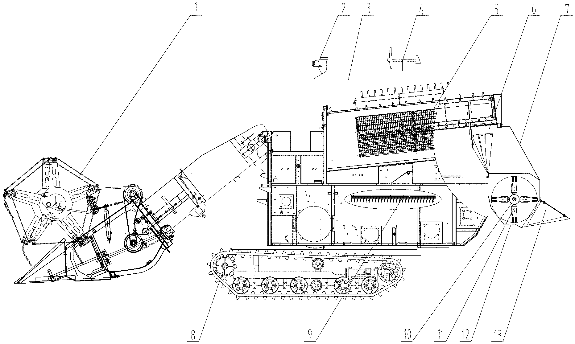
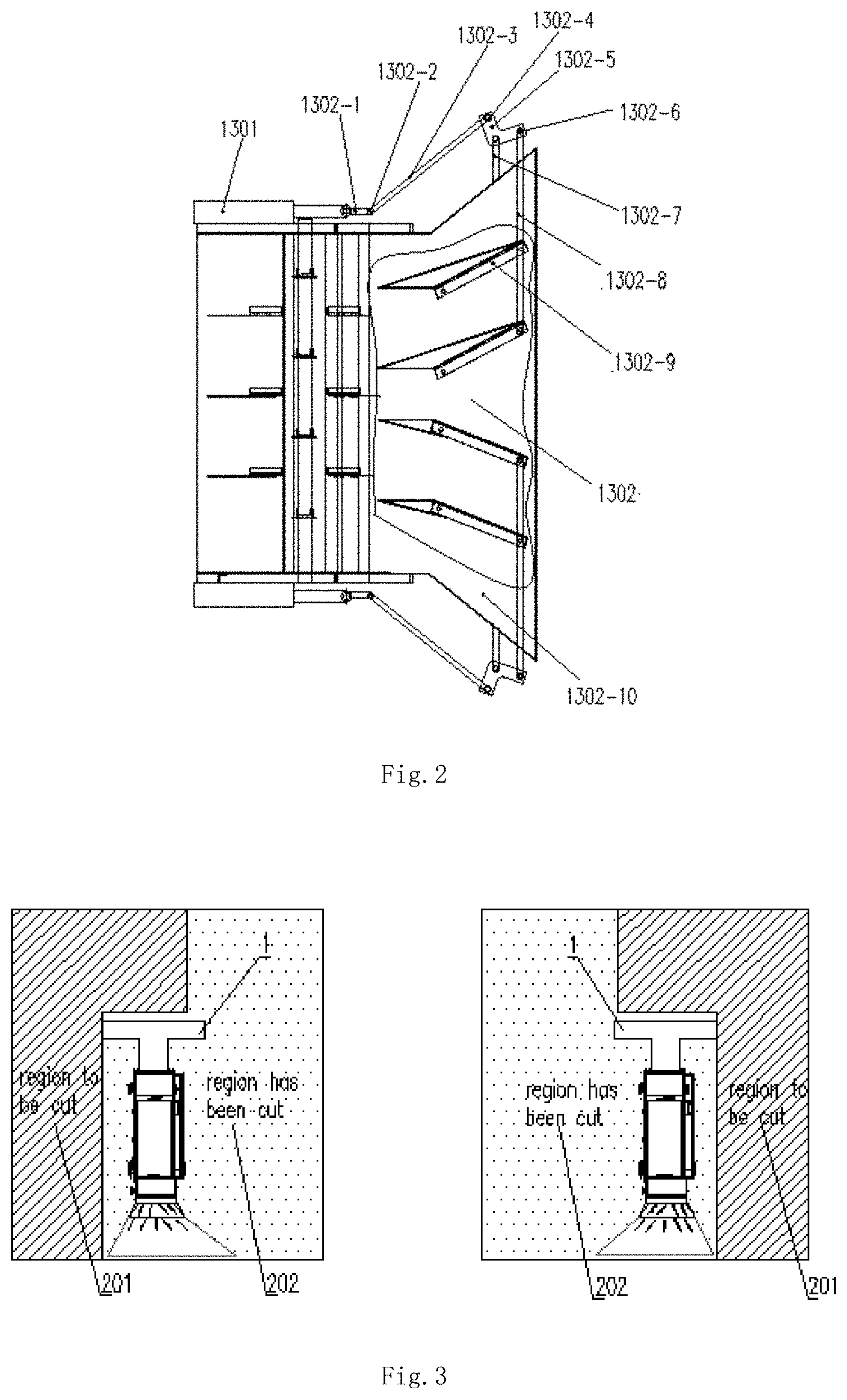
1. A self-adaptive throwing device for stalks cutting and discharging in the longitudinal axial flow combine harvesters comprising a longitudinal axial flow diverting and draining device (5), a stalk and miscellaneous smashing device (11), a wind speed detection device (4), a reaping region identification device (2), an operating speed sensor (8), a smashing rotation rate (10), an adjustable width throwing device (13), a self-adaptive throwing real-time control system; the stalk and miscellaneous smashing device (11) is located at the rear of the longitudinal axial flow diverting and draining device (5), and the adjustable width throwing device (13) is mounted on the stalk and miscellaneous smashing device (11); the wind speed detection device (4) is installed in the upper intermediate area of a combine harvester grain tank (3), and the wind speed and the wind direction at the machine work position can be measured without being blocked by other components; the reaping region identification device (2), the detection range of reaping region identification device (2) is larger than the width of a header (1), and the operating speed sensor (8) is located on the outside of combine harvester grain tank (3); the operating speed sensor (8) is mounted on a combine harvester drive wheel; the smashing rotation rate (10) is mounted on the stalk and miscellaneous smashing device (11); the self-adaptive throwing device includes a servo electric cylinder (1301) and a throwing-width adjusting mechanism (1302), which is mounted on the outside of a throwing device cover (1302-10); the input of the servo electric cylinder (1301) is connected with the self-adaptive throwing real-time control system, and the output of the servo electric cylinder (1301) is connected with a throwing width adjusting mechanism; the throwing width adjusting mechanism includes a throwing guide straw plate (1302-9), a first connecting rod (1302-8), a second connecting rod (1302-3), a third connecting rod (1302-1), a center connecting plate (1302-5), a supporting rod (1302-7), a first movable pin (1302-6), a second movable pin (1302-4), and a third movable pin surface (1302-2); the throwing guide straw plate (1302-9) is evenly distributed over the lateral width of the throwing device cover (1302-10) and the front end of the throwing guide straw plate (1302-9) is connected with throwing device cover (1302-10) by a hinge, the rear hinges with the first connecting rod (1302-8), the rear end of the throwing guide straw plate (1302-9) can be rotated at the front end hinge as an axle; the first connecting rod (1302-8) is connected to the center connecting plate (1302-5) by the first movable pin (1302-6), one end of the second rod (1302-3) passing through the third connecting rod (1302-1) is connected to one end of the third connecting rod (1302-1), and the other end of the second rod (1302-3) is connected to the center connecting plate (1302-5) through the second movable pin (1302-4), the other end of the third connecting rod (1302-1) is fixed to the rod end joint on the servo electric cylinder (1301) shaft, center connecting plate (1302-5) is mounted on the supporting rod (1302-7); the supporting rod (1302-7) is an L-shaped bar, and the center connecting plate (1302-5) is rotatable about the upper arm of the supporting rod (1302-7), and the lower arm of the supporting rod (1302-7) is fixed to the throwing device cover (1302-10); the wind speed detection device (4) is used to detect the wind direction and the wind speed at the machine working position in real time and transmit the measured wind direction and the wind speed data to the self-adaptive throwing real-time control system; The reaping region identification device comprises a CCD camera, an image processing unit and a signal output interface, the image recognition range of the CCD camera is larger than the width of the header (1), and the CCD camera is used for continuously shooting the images on both sides of header; the images on both sides of the header are extracted from the images by the image processing unit; according to the different features of the crop standing upright and neatly arranged and scattered evenly on the low stubble, region waiting for cut (201) or region having been cut (202), respectively, and then converted into a signal of control, transmitted to the adaptive throwing real-time control system; The operating speed sensor (8) is used for real-time measuring the advancing speed of the machine according to the rotational speed of the combine driving wheel and transmitting the operating speed parameter to the self-adaptive throwing real-time control system; The smashing rotation rate (10) is used for real-time measurement of the rotational speed of the shredder (1101), the short stem throwing speed is obtained, and the short stem throwing speed parameter is transmitted online to the self-adaptive throwing real-time control system; the self-adaptive throwing real-time control system considers the wind direction value, the wind speed value, the machine working speed and the short straw throwing speed parameters as the independent variables; according to the established locus model, the straw throwing real-time locus is calculated; the self-adaptive throwing real-time control system is used to calculate the position of the machine, the area of the partition and the position of the partition as the independent variable; according to the established full-width throwing model, the displacement width of the straw to calculate the actual adjustment parameters of the servo electric cylinder (1301), and then control servo electric cylinder (1301) to drive the throwing width adjustment mechanism to calculate the actual displacement parameter of servo electric cylinder (1301) by using throwing-width adjusting mechanism (1302), thus changing the inclination of the throwing guide straw plate (1302-9), to achieve the full width of the stalk residue.
2. The self-adaptive throwing device for stalks cutting and discharging in the longitudinal axial flow combine harvesters according to claim 1, wherein the number of the throwing-width adjusting mechanism (1302) is 2 to 6, and the servo electric cylinder (1301) is 2 to 6, and each of the throwing-width adjusting mechanism (1302) contains the number of the throwing guide straw plate (1302-9) is 1-3 blocks.
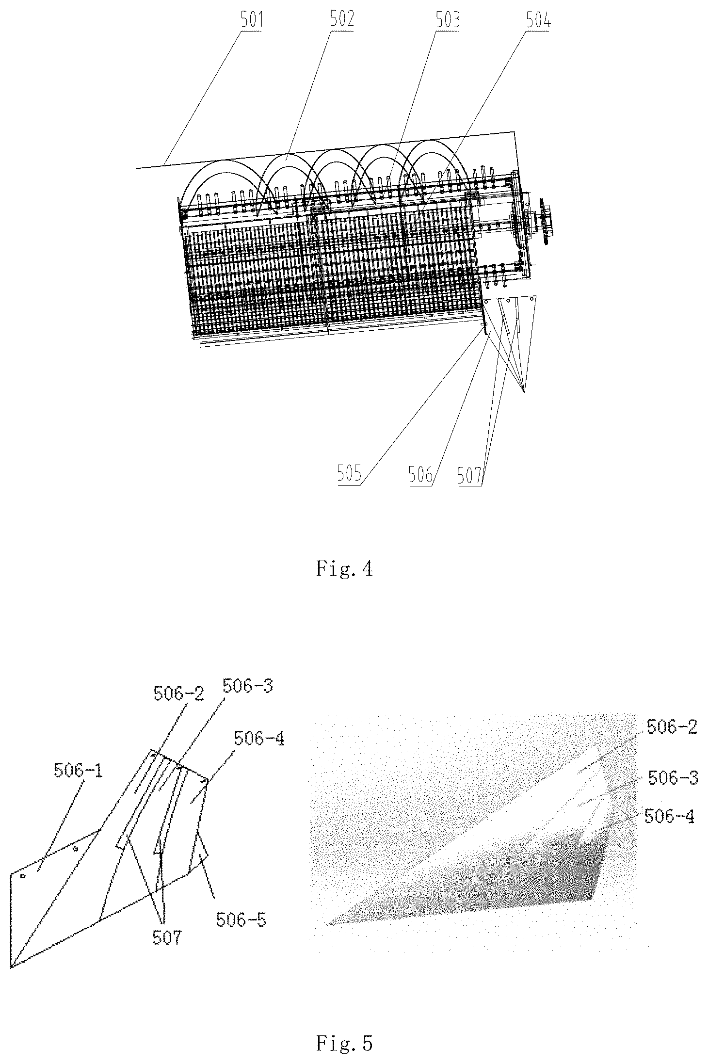
3. The self-adaptive throwing device for stalks cutting and discharging in the longitudinal axial flow combine harvesters according to claim 1, wherein the longitudinal axial flow diverting and draining device (5) comprises a longitudinal axial flow threshing cylinder (503), a longitudinal axial flow cylinder top cover (501), a longitudinal axial flow guide plate (502), a concave sieve (504), a barrier plate (505), a guide straw arc plate (506), a plurality of shunt bars (507), a longitudinal axial flow cylinder top cover (501) is located over the longitudinal axial flow threshing cylinder, and the bottom edge of longitudinal axial flow guide plate (502) is spaced from the outermost edge of the longitudinal axial flow threshing cylinder (503) by 10 mm to 130 mm, and concave sieve (504) is mounted below longitudinal axial flow threshing cylinder (503); the central axis of concave sieve is coincide with the longitudinal axial flow threshing cylinder (503), and the gap between the longitudinal axial flow threshing cylinder (503) and the concave sieve (504) is 10 mm to 60 mm, and the barrier plate (505) is mounted in the end of the concave sieve (504), the barrier plate (505) and the end of longitudinal axial flow threshing cylinder (503) compromise the width of straw outlet (6) is 200 mm to 400 mm; the guide straw arc plate (506) is located at the straw outlet (6), which is composed of two flat plates and three curved panels; the first plane (506-1) is fixed on the first plane (506-2), the second curved surface (506-3) and the third curved surface (506-4) are arranged side by side, and the side edges are successively connected, and the two flow bars (507) are respectively fixed to the first plane (506-2) and the second curved surface (506-3), the second curved surface (506-3) and the third curved surface (506-4); the first plane (506-2), the second curved surface (506-4) and the top of the third curved surface (506-4) are located on a horizontal line and fixed on the side wall of the straw outlet (6), the first curved surface (506-2), the second curved surface (506-3) and the end of the third curved surface (506-4) are also located on a horizontal line parallel to stalks and miscellaneous smashing device (11) and it is connected to the leftmost side of the stalk mashing unit is located at the bottom of the third curved surface (506-4), the second plane (506-5) is located at the bottom of the third surface (506-4), the second plane (506-5) and the trailing end of the end of the transverse width of three together form a curved surface approximating the lateral width of stalks and miscellaneous smashing device (11).
4. The self-adaptive throwing device for stalks cutting and discharging in the longitudinal axial flow combine harvesters according to claim 4, wherein the number of the longitudinal axial flow guide plate (502) is 4-6, the longitudinal axial flow guide plate (502) is mounted in the direction of the straw outlet (6), that is the direction of flow along the straw, and longitudinal axial flow guide plate (502) of the axis was 5.degree.-20.degree. angle.
5. The self-adaptive throwing device for stalks cutting and discharging in the longitudinal axial flow combine harvesters according to claim 1, wherein the stalk and miscellaneous smashing device (11) includes the upper cover of shredder (7), the shredder (1101), and the baseboard of shredder (12); the axis of the shredder (1101) is located at 0 mm to 200 mm below upper sieve surface of the cleaning device (9); and the upper cover of shredder (7), the guide straw arc plate (506), and the baseboard of shredder (12) are formed with a space of about 0.25 m.sup.3.
6. The self-adaptive throwing device for stalks cutting and discharging in the longitudinal axial flow combine harvesters according to claim 5, wherein the shredder (12) is located 0 mm to 130 mm below upper sieve surface of the cleaning device (9).
7. The adaptive throwing real-time control method for a self-adaptive throwing device for stalks cutting and discharging in the longitudinal axial flow combine harvesters according to claim 1, wherein: (1) During the combine operation, the adaptive throwing real-time control system obtains the wind direction value and the wind speed value at the machine working position through wind speed detection device (4), and operating speed sensor (8) realizes the machine working speed, smashing rotation rate (10) acquires the short stem throwing speed in real time, and reaping region identification device (2) realizes the parameters such as the direction of the machine walking, the position of the area to be cut and the position information of the cut, to characterize the operation of the mortar status; (2) The adaptive real-time control system progresses the real-time parameters, which mainly includes suppressing the interference, improving the signal-to-noise ratio and missing the data to eliminate the influence of random and uncertain factors on the subsequent data analysis; (3) The adaptive throwing real-time control system considers the wind direction value, the wind speed value, the machine working speed and the short stem throwing speed parameter as the independent variable; according to the established trajectory model, the adaptive throwing real-time control system regards the machine's advancing direction, the area to be cut and the position parameter of the cut as an independent variable; According to the established full-width throwing model, the salvage width of the stem is calculated; (4) Adaptive throwing real-time control system according to the real-time throwing trajectory of stalk mauler and the actual throwing width of stem and mortar, the fuzzy control theory is used to calculate the actual adjustment parameters of servo electric cylinder (1301) and then control servo; the servo electric cylinder (1301) drives throwing-width adjusting mechanism (1302) to change the inclination of the throwing guide straw plate (1302-9), achieving the full width and width of the stalk miscellaneous.
Description
FIELD OF THE DISCLOSURE
[0001] The invention belongs to the technical field of agricultural equipment and relates to a combine and in particular for the throwing device for stalks cutting and discharging in the longitudinal axial flow combine harvesters and its control method.
BACKGROUND OF RELATED ART
[0002] The present combine harvesters in the work need to be equipped with straw crushing and throwing device, its function is that the threshing after the production of stalks and other debris discharge, evenly covering the field after crushing device shredding out of the machine. On the one hand, the device can crush stalks. Farmers do not need to collect and burn it and decrease labor costs. At the same time it avoids environmental pollution; on the other hand, after crushing the stalks, the stalks can directly permeate into the soil as a fertilizer and enhance the fertility of soil and play a role in increasing output of crop.
[0003] China National Patent CN2050301413U publishes a new type of longitudinal axial combine straw smash machine, designed a new type of blade structure and fan-assisted structure, the main axis of the use of local multiple-spiral design is to solve the traditional longitudinal axial smash machine fixed knife blade cutting stalks, missing cut and other issues, and it has a wide throw, high-security features. But the structure of the model is more complex, smaller stalks space, cannot meet a large amount of feed the combined harvester crushed to disperse the demand.
[0004] China patent CN2040314130U publishes a shredder that is suitable for using in a self-propelled combine harvester which is mounted at the outlet of the combine harvesters and has a guide plate in the lawn mower to uniformly disperse the broken straw in the ground, but the threshing from the threshing drum into the stalks when the flow direction of the stem concentrated in a position, cannot be effectively spread, local crusher load is too large, reducing the efficiency of crushing and throwing, and the inclination of guide plate cannot be adjusted adaptively.
[0005] China patent CN2051356144U publishes a new type of straw grinder suitable for full feed-type combine with its active blade staggered with the driven blade, and the driving shaft is connected with the power transmission shaft drive of the combine harvesters. The model is simple and low power consumption. Although there is stalks guide board, crushed stalks in the model at the export of uneven distribution did not achieve diffusion, the effect is not ideal.
[0006] In addition to the technical shortcomings described above, the above-mentioned patent cannot achieve the smashing and full-width dispel version of the mismatches discharged from the end surface of the shredded shaker of the combine harvesters.
[0007] What is more, with the formation of large-scale grain production in family farms of our country and the expansion of the acreage of high-yielding crops gradually, the combine requirements under the large feed volume and the full width and width are put forward. The processing capacity and capacity of the traditional straw crushing and dispensing device used in the existing market do not match the harvest flow rate of the large feed, and the effect of the crushing and scattering of the stalk is not satisfactory.
SUMMARY
[0008] To solve the technical shortcomings of the above-mentioned stalks crushing and dispensing device, there is a kind of self-adaptive throwing device for stalks cutting and discharging in the longitudinal axial flow combine harvesters and its control system with an large feed quantity to meet the requirements of throwing at 5 to 14 kg/s, and compact structure, threshing after the stem and sieve surface discharge of the miscellaneous can be effectively crushed and scattered, large stalks, large crushing efficiency, throwing evenly. The width can be adjusted adaptively.
[0009] The technical scheme adopted by the invention is as follows:
[0010] The characteristic of self-adaptive throwing device for stalks cutting and discharging in the longitudinal axial flow combine harvesters and its control method is that it compromises with the longitudinal axial flow diverting and draining device, stalks and miscellaneous smashing device, the wind speed detection device, reaping region identification device, operating speed sensor, smashing rotation rate, smashing rotation rate, the self-adaptive throwing real-time control system.
[0011] The stalk smashing device is located at the rear of the longitudinal axial flow diverting and draining device, and the adjustable width throwing device is mounted on the straw operating speed sensor side of the stalk smashes. The wind speed detection device is installed in the upper intermediate area of the combine harvester grain tank, and the wind speed and the wind direction at the machine work position can be measured without being blocked by other components. The reaping region identification device, the detection range of the reaping region identification device is larger than the width of the header, and the operating speed sensor is located on the outside of the combine harvester grain tank. The operating speed sensor is mounted on the combine harvester drive wheel; the smashing rotation rate sensor is mounted on the stalk smashing device.
[0012] The adjustable width throwing device includes a servo electric cylinder and a throw-width adjusting mechanism, which are mounted on the outside of the throwing device housing. The input of the servo electric cylinder is connected with the self-adaptive throwing real-time control system, and the output of the servo electric cylinder is connected with a throw-width adjusting mechanism. The throw-width adjusting mechanism includes throwing guide straw arc plate, a first connecting rod, a second connecting rod, a third connecting rod, an center connecting plate, supporting rod, a first movable pin roll, a second movable pin roll and a third movable pin roll. The throwing guide straw arc plate are evenly distributed over the lateral width of the throwing device housing and the front end of the throwing guide straw arc plate is connected with a throwing device housing by a hinge, the rear hinges with the first connecting rod, the rear end of the throwing guide straw arc plate can be rotated at the front end hinge as an axis. The first connecting rod is connected to the center connecting plate by a first movable pin roll, one end of the second connecting rod passing through the third movable pin roll is connected to one end of the third connecting rod, and the other end of the second connecting rod is connected to the center connecting plate through the second movable pin roll, The other end of the third connecting rod is fixed to the rod end joint on the servo electric cylinder shaft, the intermediate connection plate is mounted on the supporting rod. The supporting rod is an L-shaped bar, and the center connecting plate is rotatable about the upper arm of the supporting rod, and the lower arm of the supporting rod is fixed to the throwing device housing.
[0013] The wind speed detection device is used to detecting the wind direction and the wind speed at the machine working position in real time and transmitting the measured wind direction and the wind speed data to the self-adaptive throwing real-time control system;
[0014] The reaping region identification device comprises a CCD camera, an image processing unit and a signal output interface, the image recognition range of the CCD camera is larger than the width of the header, and the CCD camera is used for continuously shooting the images on both sides of the header. The images on both sides of the header are extracted from the images by the image processing unit. According to the different features of the crop standing upright and neatly arranged and scattered evenly on the low stubble, the joint or the cut, respectively, and then converted into a signal of control, transmitted to the adaptive throwing real-time control system;
[0015] The operating speed sensor is used for real-time measuring the advancing speed of the machine according to the rotational speed of the combine driving wheel and transmitting the operating speed parameter to the self-adaptive throwing real-time control system;
[0016] The pulverizing speed sensor is used for real-time measurement of the rotational speed of the shredder, the short stem throwing speed is obtained, and the short stem throwing speed parameter is transmitted online to the self-adaptive throwing real-time control system;
[0017] The self-adaptive throwing real-time control system considers the wind direction value, the wind speed value, the machine working speed and the short straw throwing speed parameter as the independent variables. According to the established locus model, we can calculate the straw throwing real-time locus. The self-adaptive throwing real-time control system is used to calculate the position of the machine, the area of the partition and the position of the partition as the independent variable. According to the established full-width throwing model, the displacement width of the straw to calculate the actual adjustment parameters of the servo electric cylinder, and then control the servo electric cylinder to drive the throwing width adjustment mechanism to calculate the actual displacement parameter of the servo electric cylinder by using the fuzzy control theory, thus changing the inclination of The throwing guide straw arc plate, to achieve the full width of the stalk residue.
[0018] Further the number of the throw-width adjusting mechanism is 2 to 6, and the servo electric cylinder is 2 to 6, and each of the throw-width adjusting mechanisms contains the number of the throwing guide straw arc plate is 1-3 blocks.
[0019] Further the longitudinal axial flow diverting and draining device comprises a longitudinal axial flow threshing cylinder, a longitudinal axial flow cylinder header, a longitudinal axial flow guide plate, a concave sieve, a barrier plate, guide straw arc plate, shunt bars, a longitudinal axial flow cylinder header is located over the longitudinal axial flow threshing cylinder, and the bottom edge of the longitudinal axial flow guide plate is spaced from the outermost edge of the longitudinal axis threshing cylinder by 10 mm to 130 mm, and the concave sieve is mounted below the longitudinal axial flow threshing cylinder. The central axis of concave sieve is coincide with the longitudinal axial flow threshing cylinder, and the gap between the longitudinal axial flow threshing cylinder and the concave sieve is 10 mm to 60 mm, and the barrier plate is mounted in the end of the concave sieve, the barrier plate and the end of longitudinal axial flow threshing cylinder compromise the width of straw outlet is 200 mm to 400 mm. The guide straw arc plate is located at the straw outlet, which is composed of two flat plates and three curved panels; the first plane is fixed on the second plane, the second curved surface and the third surface are arranged side by side, and the side edges are successively connected, and the two flow bars are respectively fixed to the and the second curved surface, the second curved surface and the third curved surface, the first curved surface, the second curved surface, the top of the third curved surface being located on a horizontal line and fixed on the side wall of the straw outlet, the first curved surface, the second curved surface, the end of the third curved surface is also located on a horizontal line parallel to the transverse direction of the stalk mashing device and it is connected to the leftmost side of the stalk mashing unit is located at the bottom of the third surface, the second plane is located at the bottom of the third surface, the second plane. The trailing end of the end of the transverse width of three together forms a curved surface approximating the lateral width of the stalk smashing device.
[0020] Further the number of the longitudinal axial flow guide plate is 4-6, the vertical and horizontal axial flow guide plate is mounted in the direction of the straw outlet, that is, the direction of flow along the straw, and the vertical and horizontal axial flow guide plate of the axis was 5.degree.-20.degree. angle.
[0021] Further the stalk smashing device includes the upper cover of shredder, the shredder and the baseboard of shredder. The axis of the shredder is located at 0 mm to 200 mm below the upper upper sieve surface of the cleaning device. The upper cover of shredder, guide straw arc plate, and the baseboard of shredder are formed with a space of about 0.25 m3.
[0022] Further the baseboard of shredder is located 0 mm to 130 mm below the upper sieve surface of the cleaning device.
[0023] The adaptive throwing real-time control method for a vertical shunt combination harvester shredder adaptive shredder device according to any one of claims 1 to 6, characterized by following steps:
[0024] (1) During the combine operation, the adaptive throwing real-time control system obtains the wind direction value and the wind speed value at the machine working position through the wind speed and direction detection device (4), and the operating speed sensor (8) realizes the machine working speed, the smashing rotation rate sensor (10) acquires the short stem throwing speed in real time, and the reaping region identification device (2) realizes the parameters such as the direction of the machine walking, the position of the area region waiting for cut and the position information of the cut, to characterize the operation of the mortar status;
[0025] (2) The adaptive real-time control system processes the real-time parameters, which mainly includes suppressing the interference, improving the signal-to-noise ratio and missing the data to eliminate the influence of random and uncertain factors on the subsequent data analysis.
[0026] (3) The adaptive throwing real-time control system considers the wind direction value, the wind speed value, the machine working speed and the short stem throwing speed parameter as the independent variable. According to the established trajectory model, the adaptive throwing real-time control system regards the machine's advancing direction, the area region waiting for cut and the position parameter of the cut as an independent variable. According to the established full-width throwing model, calculate the salvage width of the stalk.
[0027] (4) Adaptive throwing real-time control system according to the real-time throwing trajectory of stalk and the actual throwing width of stem and mortar, the fuzzy control theory is used to calculate the actual adjustment parameters of servo electric cylinder and then control servo. The servo electric cylinder drives throw-width adjusting mechanism to change the inclination of the throwing guide straw arc plate, achieving the full width and width of the stalk miscellaneous.
[0028] In above view, the throwing width of the invention can adapt and adjust according to the parameters such as the machine working speed, wind speed, wind direction, the cut area and the position of the cutting area, so as to realize the full width and width of the stalk miscellaneous, The stems and shreds are uniformly scattered in the field, and it is also possible to avoid the scattering of the stem and the stem to the area region waiting for cut. The present invention has a good adaptability to the large feed amount of the combined harvester, In the case of longitudinal axis of the combined harvester of the crushed stalks.
[0029] In addition, according to the invention, the guide straw arc plate and the shunt bar are arranged at straw outlet, and the stem is guided by the diversion of the guide straw arc plate and the branching bar, and the stalk is spread into three stalks, the transverse width of the inlet of the stalk miscellaneous unit is relatively uniform, so that the crushing load of the stalk miscellaneous smashing unit is relatively uniform. The space between the traditional stalks crushing and dispersing device and the longitudinal axis roller is small, and in the case of large feeding amount, The discharge of straws, broken spike and so on the number is also greatly increased, prone to blockage, and the program will be shredded down, increase the capacity of stalks space, to solve the longitudinal axis of the threshing roller caused by excessive row of stalks is not smooth, broken stalks and other issues.
[0030] By reducing the position of the shredder, the scavenging of the sieved surface of the cleaning device can also be entered into the shredder, where the surplus and the stalks are simultaneously smashed and scattered, and the air flow formed by the rotten blade is enhanced. The speed of the air flow on the upper sieve surface of the cleaning device is beneficial to the discharge of the end above the sieve surface and improvement of the cleaning performance.
BRIEF DESCRIPTION OF THE DRAWINGS
[0031] FIG. 1 is a vertical view of the vertical axis flow combine shredder self-adaptive throwing device structure.
[0032] FIG. 2 is a schematic plan view of the adjustable width throwing device.
[0033] FIG. 3 is a schematic diagram of the working conditions of the vertical axis flow combine shredder self-adaptive throwing device
[0034] FIG. 4 is a schematic vertical view of the structure of the longitudinal axis flow guide system.
[0035] FIG. 5 is a three-dimensional diagram of the three-dimensional surface of the guide stalk plate, the upper right 45.degree. of the shunt bar, and the three surfaces of the guide stalk plate.
[0036] FIG. 6 is a schematic elevation view of the structure of the vertical axis flow combine shredder self-adaptive throwing device.
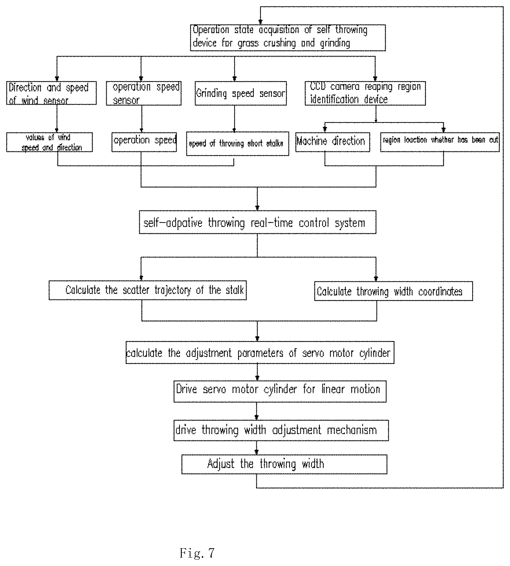
[0037] FIG. 7 is a flow chart showing the operation of the vertical axis flow combine shredder self-adaptive throwing device.
[0038] In the figures:
[0039] 1. Header; 2. Reaping region identification device; 3. Combine harvester grain tank; 4. Wind speed detection device; 5. Longitudinal axis flow diverting and draining device; 6. Straw outlet; 7. Upper cover of shredder; 8. Operating speed sensor; 9. Upper sieve surface of the cleaning device; 10. Smashing rotation rate sensor; 11. Stalks and miscellaneous smashing device; 12. Baseboard of shredder; 13. Adjustable width throwing device; 201. Region waiting for cut; 202. Region having been cut; 501. Longitudinal axial flow cylinder header; 502. Longitudinal axial flow guide plate; 503. Longitudinal axial flow threshing cylinder; 504. Concave sieve; 505. Barrier plate; 506. Guide straw arc plate; 507. Shunt bars; 1101. Shredder; 1301. Servo electric cylinder; 1302. Throw-width adjusting mechanism; 506-1. The first plane; 506-2. The second plane; 506-3. The second curved surface; 506-4. The third curved surface; 506-5. The second plane; 1302-1. The third connecting rod; 1302-2. The third surface; 1302-3. The second rod; 1302-4. The second movable pin; 1302-5. Center connecting plate; 1302-6. The first movable pin; 1302-7. Supporting rod; 1302-8. The first connecting rod; 1302-9. Throwing guide straw arc plate; 1302-10. Throwing device cover.
DETAILED DESCRIPTION
[0040] The present invention will now be described further with reference to the accompanying drawings and specific examples, but the scope of the present invention is not limited thereto.
[0041] FIG. 1 shows the vertical axis flow combine shredder self-adaptive throwing device structure of the structure of the left side of the vertical, vertical axis of the combination of harvesting machine straw crushing adaptive throwing device, including the longitudinal axis flow drainage guide 5, the stalk smashing device 11, the wind speed detection device 4, the reap region identification device 2, operating speed sensor 8, the smashing rotation rate sensor 10, an adjustable width dispersing device 13, and an adaptive throwing real-time control system. The stalk smashing device 11 is located at the rear of the longitudinal axis flow diverting and draining device 5, and the adjustable width throwing device 13 is mounted on the straw operating speed sensor side of the stalk smashes 11. The wind speed detection device 4 is installed in the upper intermediate area of the combine harvester grain tank 3, and the wind speed and the wind direction at the machine work position can be measured without being blocked by other components. The reaping region identification device 2, the detection range of the reaping region identification device 2 is larger than the width of the header 1, and the operating speed sensor 8 is located on the outside of the combine harvester grain tank (3). The operating speed sensor is mounted on the combine harvester drive wheel; the smashing rotation rate sensor 10 is mounted on the stalk smashing device 11. The stalks after the threshing process is diverted and diffused in the longitudinal axis flow guide system 5 and discharged evenly into the stalk mashing unit 11 and then pulverized into the adjustable width dispersing device 13, field. The wind speed detecting device 4, the zone identification device 2, the working speed sensor 8, and the pulverizing speed sensor 10 to transmit the measured parameters online to the adaptive dispatching real-time control system, and the control of the real--The amplitude-width dispersing device 13, thereby realizing the adaptive adjustment of the throwing width.
[0042] FIG. 2 shows a schematic plan view of the adjustable width dispersing device. Which includes a servo electric cylinder 1301, a throw-width adjusting mechanism 1302. The servo motor cylinder 1301 and the throw-width adjusting mechanism 1302 are mounted on the outside of the throwing device housing 1302-10, the input end of the servo motor cylinder 1301 is connected to the adaptive throwing real time control system, the output end of the servo motor cylinder 1301 and the throwing width. The adjustment mechanism 1302 is connected. The throw-width adjusting mechanism 1302 is composed of a wiper guide plate 1302-9, a first connecting rod 1302-8, a second connecting rod 1302-3, a third connecting rod 1302-1, an center connecting plate 1302-5, a support bar 1302-7, a first movable pin 1302-6, a second movable pin 1302-4, and a third movable pin 1302-2. The servo electric cylinder 1301 is mounted on the outside of the throwing device housing 1302-10, and the worn guide plate 1302-9 is evenly distributed over the lateral width of the throwing device housing 1302 to 10, and the front end thereof is connected to the throwing device casing 1302-10 by a hinge, The rear end is mounted on the first connecting rod 1302-8 and the rear end of the wiper guide plate 1302-9 is rotatable with the front hinge axis, and the guide plate 1302-9 and the first connecting rod 1302-8 are also moved by a hinge, The first connecting rod 1302-8 is connected to the intermediate connection plate 1302-5 through the first movable pin 1302-6, and one end of the second connecting rod 1302-3 passes through the third movable pin 1302-2 and the third connecting rod. One end of the rod 1302-1 and the other end of the second connecting rod 1302-3 is connected to the center connecting plate 1302-5 through the second movable pin 1302-4, and the other end of the third connecting rod 1302-1 is fixed to the servo The intermediate connection plate 1302-5 is mounted on the support rod 1302-7, the support rod 1302-7 is an L-shaped bar, and the intermediate connection plate 1302-5 is capable of supporting the lever 1302-7 upper arm And the lower end of the support rod 1302-7 is fixed to the side of the throwing device housing 1302-10. The number of the throw-width adjusting mechanisms 1302 is two, and accordingly, the number of the servo motor cylinders 1301 is two, and the number of the worn-out guides 1302-9 included in each of the throw-width adjusting mechanisms 1302 is 2 (I.e., the left side servo motor cylinder 1301 is mounted on the inside of the throwing device housing in the axial direction, and the servo motor cylinder 1301 on the left side is controlled by the throw-width adjusting mechanism 1302, The inclination of the two guide pieces 1302-9 on the right side can be individually adjusted by controlling the throw-width adjusting mechanism 1302 on the right side of the servo motor cylinder 1301 on the right side. The adaptive throwing real-time control system can control the servo motor cylinder 1301 on the left and right sides to move linearly, and then the adjustment of the inclination angle of the guide plate 1302-9 on the left and right sides is completed respectively to achieve the purpose of adjusting the throwing width.
[0043] FIG. 3 shows a schematic diagram of the working conditions of the vertical shrinking combine harvester for the crushing and crushing of the self--When the left side of the combined harvester is oriented to the area 201 and the right side is the region having been cut 202, the adaptive throwing real-time control system controls the servo motor cylinders 1301 on the left and right sides of the adjustable width dispersing device 13 to move the left side Of the two pieces of the draft guide plate 1302-9 slightly inclined to the left, the right side of the two pieces of the stalks guide plate 1302-9 tilt significantly biased to the right, so that the stem cannot be scattered to the left The grain is removed from the crop of the zone 201, and the width of the throwing is spread as far as possible to the region having been cut 202, which facilitates the uniform tiling of the stem and the scum in the field; when the joint harvester advances to the left Zone 202 and the right side are the to-be-cut area 201, the adaptive throwing real-time control system controls the servo motor cylinders 1301 on the left and right sides of the adjustable width dispersing device to move the inclination of the two pieces of the left side The inclination of the two pull-on guide plates 1302-9 is slightly biased to the right, so that the stem and the stump cannot be dispelled to the crop of the cutting zone 201 to prevent the grain from falling off Throwing the width as much as possible to the cut The area 202 diffuses, which facilitates the grinding of the stem and the mound in the field evenly.
[0044] FIG. 7 shows the working flow chart of the vertical abutment combined harvester crusher crushing adaptive dispensing device. When the combined harvester performs the harvesting operation, the adaptive throwing real-time control system obtains the wind direction value and the wind speed value at the machine work position in real time by the wind direction wind speed detecting device 4, and the working speed sensor 8 obtains the machine working speed in real time and obtains the real--And the zone identification device 2 realizes the parameters such as the machine advancing direction, the to-be-cut area 201, and the position information of the divided area 202 to indicate the working state of the mortar-smashing adaptive throwing device. The adaptive real-time control system prepossess the real-time parameters, which mainly includes suppressing the interference, improving the signal-to-noise ratio and missing the data to eliminate the influence of random and uncertain factors on the subsequent data analysis. The self-adaptive real-time control system is used to calculate the wind direction value, wind speed value, machine speed and short stem throwing speed parameter as independent variables. According to the established trajectory model, the real-time control system treats the positional parameters of the machine forward direction, the area region waiting for cut 201 and the divided area 201 as independent variables, and calculates the throwing width required for the real time of the stem in accordance with the established full width sweep model. The servo motor cylinder 1301 drives the throwing width adjustment mechanism 1302 by calculating the actual adjustment parameter of the servo motor cylinder 1301 by using the fuzzy control theory according to the real--Thereby changing the inclination of the guide straw arc plate 1302-9, to achieve the adaptive adjustment of the full width of the stalk residue.
[0045] As shown in FIG. 4, the longitudinal axis flow deflector 5 includes a longitudinal axial catastrophic drum 503, a longitudinal axial drum cap 501, a longitudinal axial flow guide plate 502, a veneer screen 504, a scraper plate 505, guide straw arc plate 506, and shunt bar 507. The longitudinal axial flow roller cap 501 is located above the longitudinal axial flow threshing cylinder 503. The longitudinal axial flow guide plate 502 is mounted on the inner wall of the longitudinal shaft roller cap 501, is located at a distance of 10 mm to 130 mm from the outermost edge of the longitudinal axial catastrophic drum 503. The concave plate sieve 504 is mounted below the longitudinal axial flow threshing cylinder 503. The center line of the veneer screen 504 coincides with the axis of the longitudinal axial flow threshing cylinder 503 The gap between the axial-flow threshing drum 503 and the rotogravure plate 504 is 10 mm to 60 mm, the hatch plate 505 is attached to the tail of the gusset plate 504, and the scraper plate 505 is formed with a width of 200 mm-400 mm. The guide straw arc plate 506 is mounted on the wick 505 and is located inside the straw outlet 6, and the shunt bar 507 is mounted on the guide straw arc plate 506. As shown in FIG. The stalk after the threshing process enters straw outlet 6 under the action of the rotation of the longitudinal axial flow guide plate 502 and the longitudinal axial flow threshing cylinder 503, and then passes through the diversion and shunt bars 507 of the guide rock plate 506, And the transverse width of the expanded stalks belt is close to the lateral width of the inlet of the stalk mashing unit 11 so that the crushing capacity of the stalk mashing unit 11 is relatively uniform.
[0046] FIG. 5 shows the structure of the guide rock plate and the upper right 45.degree. angle of the shunt. The guide curved plate 506 is an arc plate composed of two flat plates and three curved panels, the first plane 506-1 is fixed to the stalks plate 505, the first curved surface 506-2, the second curved surface 506-3, The third surface 506-4 is arranged side by side and the sides are successively connected, and the two flow bars 507 are fixed to the first surface 506-2 and the second curved surface 506-3, the second curved surface 506-3 and the third surface 506-4 The first surface 506-2, the second curved surface 506-3, and the top of the third surface 506-4 are located on a horizontal line and fixed to the side wall of the row of mouth 6, the first surface 506-2, The second curved surface 506-3 and the third curved surface 506-4 are also located on a horizontal line and connected to the leftmost side of the stalk mashing unit 11 and parallel to the transverse direction of the stalk mashing unit 11; And the second plane 506-5 is located below the third surface 506-4 and the trailing end of the second plane 506-5 is at the rear end of the three surfaces The generally formed transverse width is similar to the lateral width of the stalk mashing device 11. The guide straw arc plate 506 and the shunt bar 507 serve to divert and diffuse the stem.
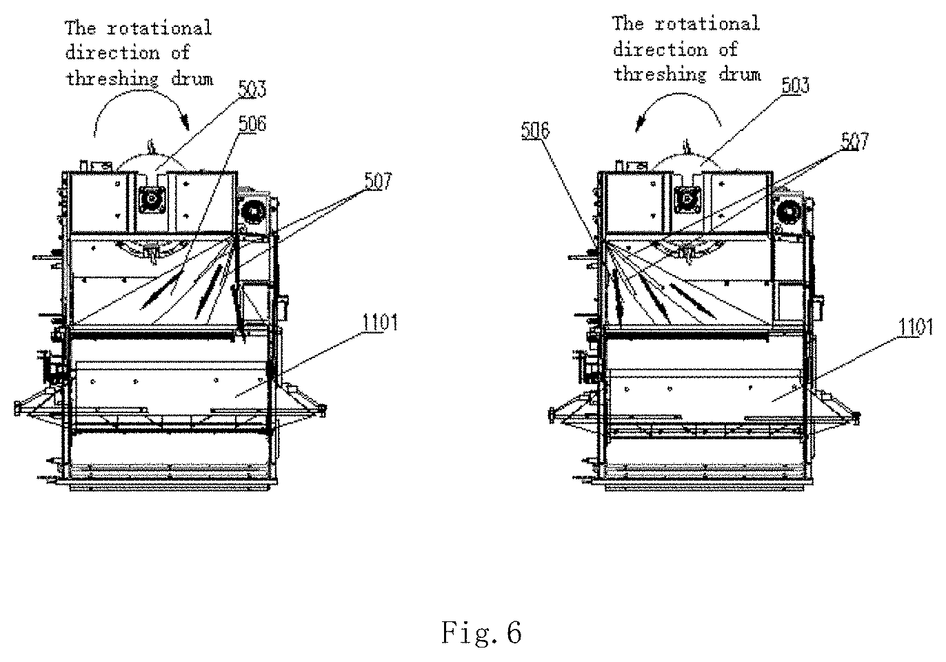
[0047] As shown in FIG. 6, the structure is a schematic rear view of the vertical shunt combine harvester for the crushing of the self--In the direction of the rear view, if the rotational direction of the longitudinal axis threshing roller 503 is clockwise, the stalk at straw outlet 6 is diffused from the upper right by the diversion and diffusion of the guide straw arc plate 506 and the bypass bar 507 To the entire axial direction of the shredder 1101; if the longitudinal axial flow threshing drum 503 is rotated counterclockwise, the guide rock plate 506 may be modified slightly and the structure of the guided rock plate 506 along the longitudinal axis of the threshing drum 503 vertical center line Symmetrical reversal, while removing the second plane 506-5, to achieve the straw at straw outlet 6 at the stalks through the arc and the role of the shunt, from the top left spread to the entire range of the shredder 1101.
[0048] As shown in FIGS. 1, 6, the stalk mashing device 11 comprises the upper cover of shredder 7, a shredder 1101 and the baseboard of shredder 12. The axis of the shank 1101 is located at 0 mm to 200 mm below the sieve surface 9 of the cleaning device, and the horizontal distance between the blade axis of the shredder 1101 and the innermost side of the row of slugs is 240 mm to 600 mm, 7 is connected to the outermost side of the row of slugs 6, and the lower end of the shackle upper cover 7 is connected to the shredder 1101, and between the upper cover of shredder 7, the guide straw arc plate 506 and the shredder the baseboard of shredder 12 0.25 m3 of the stalks space, to solve the longitudinal axis flow threshing roller 503 transient stalks caused by too much stalks is not smooth, broken stalks and other issues. The weaving machine the baseboard of shredder 12 is located at 0 mm to 130 mm below the upper upper sieve surface of the cleaning device 9 of the cleaning apparatus, and passes through guide straw arc plate 506 and the shunt bar 507 guides the diffused stem and the scavenging discharged from the upper upper sieve surface of the cleaning device 9 of the cleaning apparatus Into the upper cover of shredder 7, guided stalks plate 506 and the stalks plate 12 to form the stalks space, stalks and miscellaneous in the shredder 1101 action, under the action of cutting blade to achieve the crushing, crushing after The stalk and the stumps enter the adjustable width dispersing device 13 along the weaving machine the baseboard of shredder 12, improving the crushing and dispensing performance. At the same time, the air flow formed by the rotation of the blade of the shredder 1101 enhances the air flow velocity of the tail surface of the upper sieve surface of the cleaning device 9 of the cleaning apparatus, and facilitates the discharge of the tail of the upper surface of the upper sieve surface of the cleaning device 9, thereby improving the cleaning performance.
[0049] The embodiments are preferred embodiments of the present invention, but the invention is not limited to the embodiments described above, and any obvious modifications, substitutions, or alterations that may be made by those skilled in the art without departing from the spirit of the invention Variations are within the scope of the present invention.
* * * * *
D00000
D00001
D00002
D00003
D00004
D00005
XML
uspto.report is an independent third-party trademark research tool that is not affiliated, endorsed, or sponsored by the United States Patent and Trademark Office (USPTO) or any other governmental organization. The information provided by uspto.report is based on publicly available data at the time of writing and is intended for informational purposes only.
While we strive to provide accurate and up-to-date information, we do not guarantee the accuracy, completeness, reliability, or suitability of the information displayed on this site. The use of this site is at your own risk. Any reliance you place on such information is therefore strictly at your own risk.
All official trademark data, including owner information, should be verified by visiting the official USPTO website at www.uspto.gov. This site is not intended to replace professional legal advice and should not be used as a substitute for consulting with a legal professional who is knowledgeable about trademark law.