Stator Assembly With Heat Recovery For Electric Machines
SHI; RUISHENG ; et al.
U.S. patent application number 16/490253 was filed with the patent office on 2020-03-05 for stator assembly with heat recovery for electric machines. The applicant listed for this patent is TM4, INC.. Invention is credited to MARTIN HOULE, RUISHENG SHI.
| Application Number | 20200076251 16/490253 |
| Document ID | / |
| Family ID | 63369617 |
| Filed Date | 2020-03-05 |


| United States Patent Application | 20200076251 |
| Kind Code | A1 |
| SHI; RUISHENG ; et al. | March 5, 2020 |
STATOR ASSEMBLY WITH HEAT RECOVERY FOR ELECTRIC MACHINES
Abstract
The present disclosure is concerned with a stator for an electric machine comprising a plurality of stacked laminations each including inwardly facing slots defining inwardly facing teeth configured to receive prewound coils thereonto. Each slot including a generally triangular projection configured and sized as to be in proximity of the prewound coils.
| Inventors: | SHI; RUISHENG; (MONTREAL, CA) ; HOULE; MARTIN; (LAVAL, CA) | ||||||||||
| Applicant: |
|
||||||||||
|---|---|---|---|---|---|---|---|---|---|---|---|
| Family ID: | 63369617 | ||||||||||
| Appl. No.: | 16/490253 | ||||||||||
| Filed: | February 27, 2018 | ||||||||||
| PCT Filed: | February 27, 2018 | ||||||||||
| PCT NO: | PCT/CA2018/050228 | ||||||||||
| 371 Date: | August 30, 2019 |
Related U.S. Patent Documents
| Application Number | Filing Date | Patent Number | ||
|---|---|---|---|---|
| 62466093 | Mar 2, 2017 | |||
| Current U.S. Class: | 1/1 |
| Current CPC Class: | H02K 15/06 20130101; H02K 1/146 20130101; H02K 1/185 20130101; H02K 9/00 20130101 |
| International Class: | H02K 1/14 20060101 H02K001/14; H02K 1/18 20060101 H02K001/18; H02K 15/06 20060101 H02K015/06; H02K 9/00 20060101 H02K009/00 |
Claims
1. A stator for an electric machine comprising a plurality of stacked laminations each including inwardly facing slots defining inwardly facing teeth configured to receive prewound coils thereonto; each slot including a generally triangular projection configured and sized as to be in proximity of the prewound coils.
2. The stator as recited in claim 1, wherein the generally triangular projection includes a void.
3. The stator as recited in claim 1, further comprising at least one wedge used to close each slot.
4. The stator as recited in claim 1, wherein the stator includes a generally cylindrical inner surface and wherein the generally triangular projections are generally level with the generally cylindrical inner surface.
5. The stator as recited in claim 4, further comprising 2 wedges for each slot.
6. A stator for an electric machine having a generally cylindrical body provided an inner surface and an outer surface, the inner surface including slots defining inwardly facing teeth configured to receive prewound coils thereonto; each slot including a generally triangular projection configured and sized as to be in proximity of the prewound coils.
7. The stator as recited in claim 6, wherein the generally triangular projection includes a void.
8. The stator as recited in claim 6, further comprising at least one wedge used to close each slot.
9. The stator as recited in claim 6, wherein the generally triangular projections are generally level with the inner surface of the generally cylindrical body.
10. The stator as recited in claim 9, further comprising two wedges for each slot.
Description
FIELD
[0001] The present disclosure generally relates to electric machines. More specifically, the present disclosure is concerned with a stator assembly with heat recovery for an electric machine.
BACKGROUND
[0002] Electric machines such as electric motors and generators are well known in the art. They are usually provided with a stator and a rotor, both coaxially mounted to a housing.
[0003] Conventionally, stator assemblies are made of a stack of laminations that are provided with inwardly facing slots allowing coils to be formed therein. When rectangular wire is used to form the coils, the coils are generally formed prior to their insertion in the stator slots. The rectangular configuration of the wire makes it so that the stator slots are not fully filled by the coils, which leaves a void between adjacent coils, leading to a poor recovery of the heat generated in the coils when the electric machine is used.
BRIEF DESCRIPTION OF THE DRAWINGS
[0004] In the appended drawings:
[0005] FIG. 1 is a schematic end view of a stator according to a first illustrative embodiment;
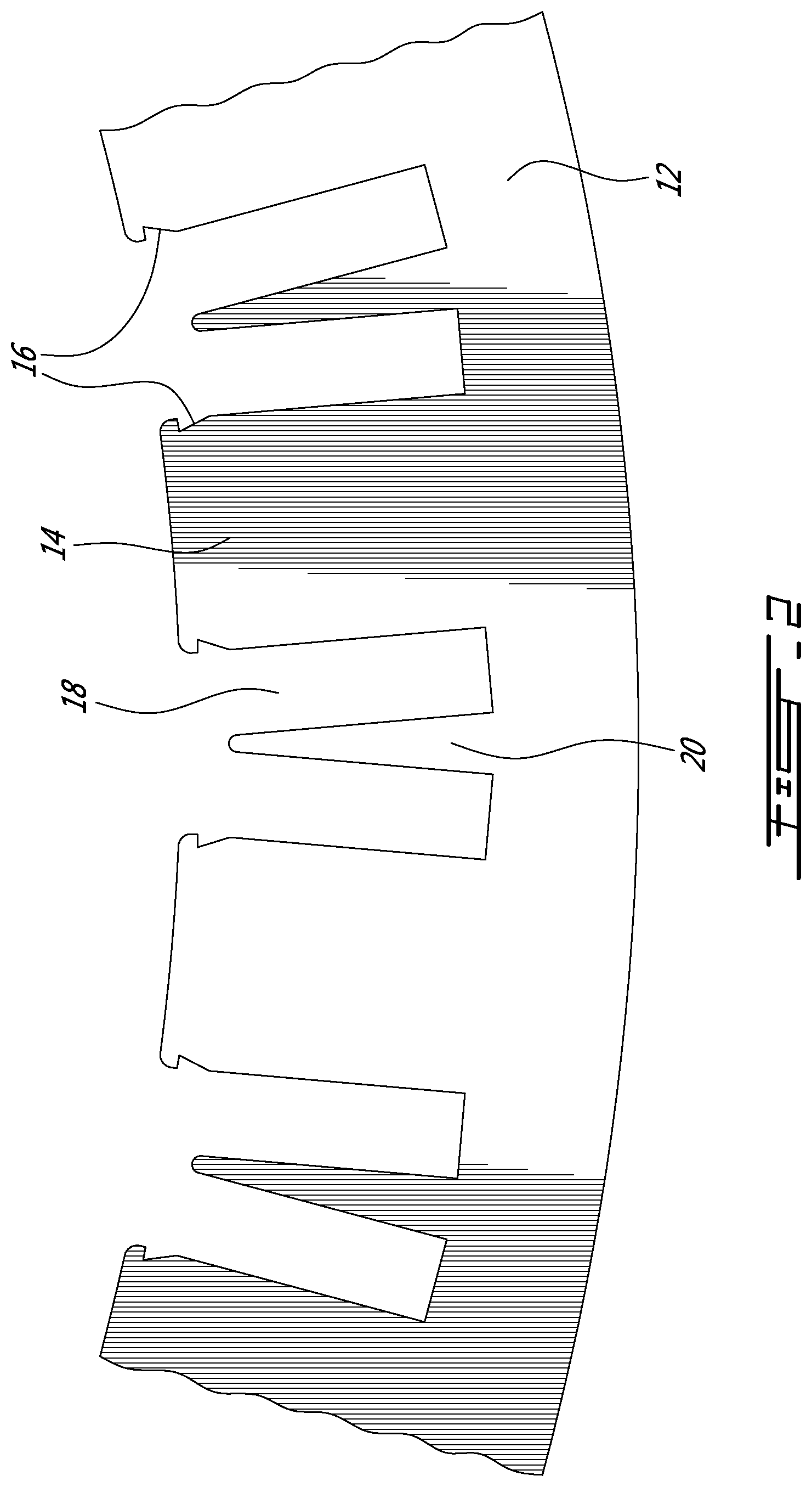
[0006] FIG. 2 is a portion of a lamination forming the stator of FIG. 1;
[0007] FIG. 3 is a sectional view taken along line 3-3 of FIG. 1;
[0008] FIG. 4 is a sectional view similar to FIG. 3, but illustrating a second illustrative embodiment; and
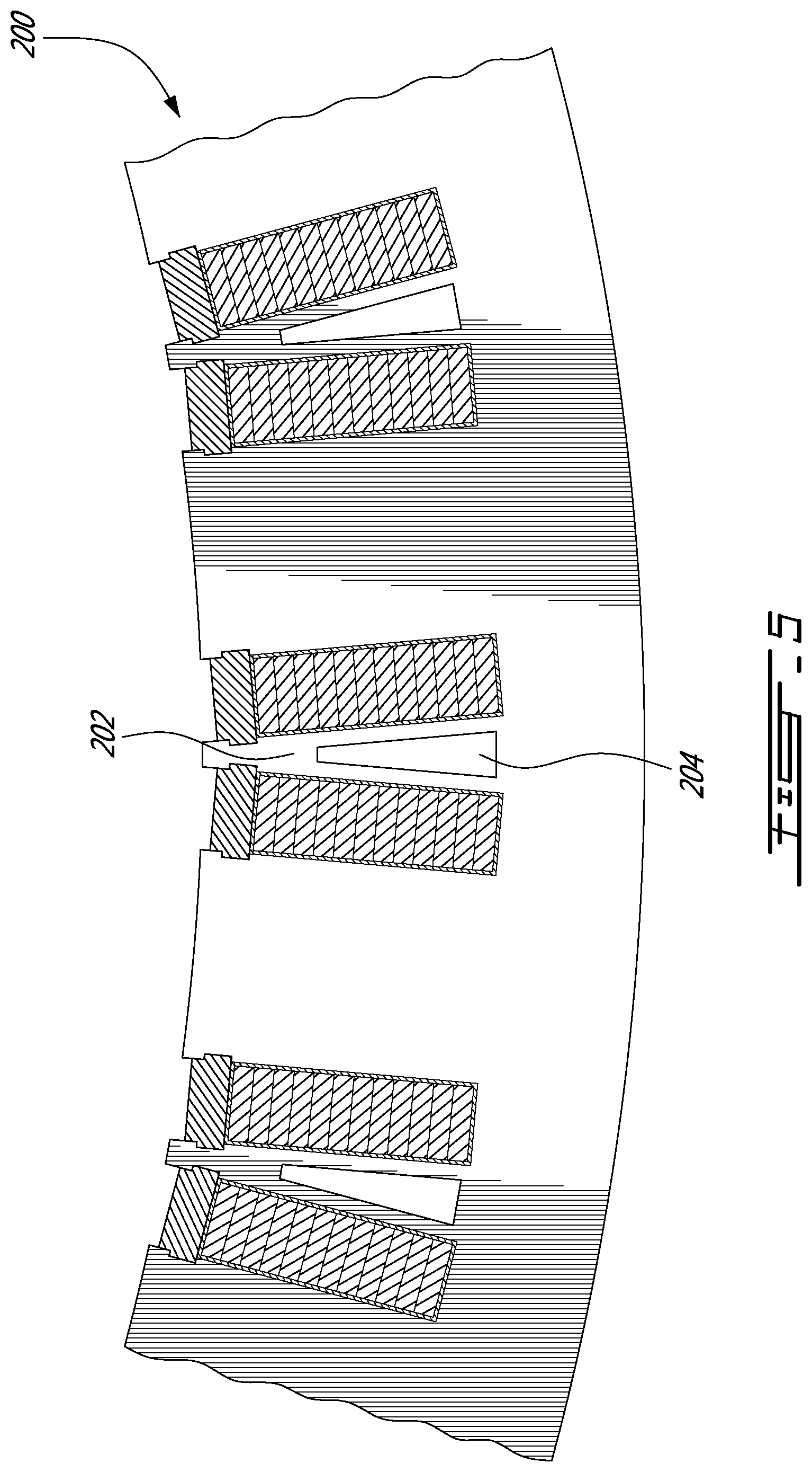
[0009] FIG. 5 is a sectional view similar to FIG. 3, but illustrating a third illustrative embodiment.
DETAILED DESCRIPTION
[0010] In accordance with an illustrative embodiment, there is provided a stator for an electric machine comprising a plurality of stacked laminations including inwardly facing slots defining inwardly facing teeth configured to receive prewound coils thereonto; each slot including a generally triangular projection configured and sized as to be in proximity of the prewound coils.
[0011] In accordance with an other aspect, there is provided a stator for an electric machine having a generally cylindrical body provided an inner surface and an outer surface, the inner surface including slots defining inwardly facing teeth configured to receive prewound coils thereonto; each slot including a generally triangular projection configured and sized as to be in proximity of the prewound coils.
[0012] The use of the word "a" or "an" when used in conjunction with the term "comprising" in the claims and/or the specification may mean "one", but it is also consistent with the meaning of "one or more", "at least one", and "one or more than one". Similarly, the word "another" may mean at least a second or more.
[0013] As used in this specification and claim(s), the words "comprising" (and any form of comprising, such as "comprise" and "comprises"), "having" (and any form of having, such as "have" and "has"), "including" (and any form of including, such as "include" and "includes") or "containing" (and any form of containing, such as "contain" and "contains"), are inclusive or open-ended and do not exclude additional, unrecited elements or process steps.
[0014] In the present specification and in the appended claims, various terminology which is directional, geometrical and/or spatial in nature such as "longitudinal", "horizontal", "front", rear", "upwardly", "downwardly", etc. is used. It is to be understood that such terminology is used for ease of description and in a relative sense only and is not to be taken in any way as a limitation upon the scope of the present disclosure.
[0015] Further, in this specification, the terms "axial direction", "axially", "axial", and the like, refer to the direction of the rotation axis of the rotor, the direction of the central axis of the cylindrical stator, and the directions corresponding to them, the terms "radial direction", "radially", "radial", and the like, refer to the directions perpendicular to such axial directions, and the terms "circumferential direction", "circumferentially", "circumferential", and the like, refer to each direction along the circumference of a circle drawn about a given point of the rotation axis on a plane perpendicular to the rotation axis.
[0016] The expression "connected" should be construed herein and in the appended claims broadly so as to include any cooperative or passive association between mechanical parts or components. For example, such parts may be assembled together by direct coupling, or indirectly coupled using further parts. The coupling can also be remote, using for example a magnetic field or else.
[0017] Other objects, advantages and features of the stator assembly with heat recovery for electric machines will become more apparent upon reading of the following non-restrictive description of illustrative embodiments thereof, given by way of example only with reference to the accompanying drawings.
[0018] Generally stated, illustrative embodiments are concerned with a stator assembly for an internal rotor electric machine using prewound coils made of rectangular wires. The inwardly facing slots in the stator each include a generally triangular projection that fills the space between adjacent coils to thereby improve the recovery of the heat generated in the coils during the operation of the electric machine.
[0019] Turning now to FIGS. 1 to 3 of the appended drawings, a stator 10 according to a first illustrative embodiment will be described.
[0020] As can be seen from FIG. 1, the stator 10 includes a plurality of generally circular laminations 12 each provided with inwardly projecting teeth 14.
[0021] As can be better seen from FIG. 2, the teeth 14 include wedge-receiving indentations 16 and define coil-receiving slots 18. Each slot 18 includes a generally triangular space filling projection 20 integral with the lamination 12. The slots 18 and projections 20 are so configured and sized that the rectangular wire forming the prewound coils 22 (see FIG. 1) with their respective insulating papers 24 can snugly fit therein.
[0022] FIG. 3 is a sectional view of FIG. 1 taken along line 3-3 of FIG. 1. As can be seen from this figure, the coils 22, wrapped in insulating paper 24 are inserted in the slots 18, space filling resin 26 has been cured about the coils 22 and wedges 28 have been inserted in the indentations 16 to close the slots 18.
[0023] One skilled in the art will understand that the generally triangular projection 20 being in close proximity of the coils 22 allow heat generated in the coils during the operation of the electric machine (not shown) to be removed from the coils.
[0024] Of course, a cooling strategy is used to remove the heat present in the stator. For example, a fluid cooling assembly (not shown) can be applied to the external surface 30 of the stator 10.
[0025] FIG. 4 illustrates a stator 100 according to a second illustrative embodiment. Generally stated, the major difference between the stator 10 and the stator 100 concerns the height of the generally triangular space filling projections 104 which are the same height as the teeth 102. In other words, the projections 104 and the teeth 102 define an inner surface of the stator 100. Accordingly, the projections 104 include wedge-receiving indentations 106 similar to the indentations 108 of the teeth 102.
[0026] Therefore, two wedges 110 are required between adjacent teeth 102 to close the coil receiving slots.
[0027] One will also notice that while the shape of the indentations 106 and 108 are different from the indentation 16 of FIG. 3, it is for illustration purpose and that these indentations could be identical.
[0028] Finally FIG. 5 illustrates a stator 200 according to a third illustrative embodiment. The stator 200 is similar to the stator 100 of FIG. 4. The major difference therebetween concerns the generally triangular space filling projection 202 that includes a generally triangular void 204.
[0029] The void 204 decreases the amount of field that flows through the projection 202. Furthermore, a non-magnetic cooling fluid could optionally be made to flow through the void 204 to thereby improve the cooling of the stator 200.
[0030] Of course, while laminations have been described as making the stator, other technologies, such as compressed metallic powders, could be used.
[0031] It is to be understood that the stator assembly with heat recovery for electric machines is not limited in its application to the details of construction and parts illustrated in the accompanying drawings and described hereinabove. The stator assembly with heat recovery for electric machines is capable of other embodiments and of being practiced in various ways. It is also to be understood that the phraseology or terminology used herein is for the purpose of description and not limitation. Hence, although the present stator assembly with heat recovery for electric machines has been described hereinabove by way of illustrative embodiments thereof, it can be modified, without departing from the spirit, scope and nature thereof.
[0032] The following clauses are provided as supplemental description:
[0033] 1. A stator for an electric machine comprising a plurality of stacked laminations each including inwardly facing slots defining inwardly facing teeth configured to receive prewound coils thereonto; each slot including a generally triangular projection configured and sized as to be in proximity of the prewound coils.
[0034] 2. The stator as recited in clause 1, wherein the generally triangular projection includes a void.
[0035] 3. The stator as recited in any of the preceding clause, further comprising at least one wedge used to close each slot.
[0036] 4. The stator as recited in any of the preceding clause, wherein the stator includes a generally cylindrical inner surface and wherein the generally triangular projections are generally level with the generally cylindrical inner surface.
[0037] 5. The stator as recited in clause 4, further comprising 2 wedges for each slot.
[0038] 6. A stator for an electric machine having a generally cylindrical body provided an inner surface and an outer surface, the inner surface including slots defining inwardly facing teeth configured to receive prewound coils thereonto; each slot including a generally triangular projection configured and sized as to be in proximity of the prewound coils.
[0039] 7. The stator as recited in clause 6, wherein the generally triangular projection includes a void.
[0040] 8. The stator as recited in any of clauses 6 to 7, further comprising at least one wedge used to close each slot.
[0041] 9. The stator as recited in any of clauses 6 to 8, wherein the generally triangular projections are generally level with the inner surface of the generally cylindrical body.
[0042] 10. The stator as recited in clause 9, further comprising two wedges for each slot.
* * * * *
D00000
D00001
D00002
D00003
D00004
D00005
XML
uspto.report is an independent third-party trademark research tool that is not affiliated, endorsed, or sponsored by the United States Patent and Trademark Office (USPTO) or any other governmental organization. The information provided by uspto.report is based on publicly available data at the time of writing and is intended for informational purposes only.
While we strive to provide accurate and up-to-date information, we do not guarantee the accuracy, completeness, reliability, or suitability of the information displayed on this site. The use of this site is at your own risk. Any reliance you place on such information is therefore strictly at your own risk.
All official trademark data, including owner information, should be verified by visiting the official USPTO website at www.uspto.gov. This site is not intended to replace professional legal advice and should not be used as a substitute for consulting with a legal professional who is knowledgeable about trademark law.