Plant Monitoring Method Using Exergy Efficiency Value
PARK; Jung Won ; et al.
U.S. patent application number 16/553164 was filed with the patent office on 2020-03-05 for plant monitoring method using exergy efficiency value. The applicant listed for this patent is DOOSAN HEAVY INDUSTRIES & CONSTRUCTION CO., LTD.. Invention is credited to Yeong Hyeok KIM, Jung June LEE, Jung Won PARK.
| Application Number | 20200073364 16/553164 |
| Document ID | / |
| Family ID | 69527466 |
| Filed Date | 2020-03-05 |


View All Diagrams
| United States Patent Application | 20200073364 |
| Kind Code | A1 |
| PARK; Jung Won ; et al. | March 5, 2020 |
PLANT MONITORING METHOD USING EXERGY EFFICIENCY VALUE
Abstract
A plant monitoring method using exergy efficiency is provided. The plant monitoring method includes detecting data associated with chemical exergy and physical exergy of each apparatus or subsystem and obtaining a chemical exergy value and a physical exergy value of each apparatus or subsystem, calculating an exergy efficiency value of each apparatus or subsystem on the basis of the detected data, and identifying a maintenance target which refers to an apparatus or subsystem that needs to be improved in efficiency on the basis of data obtained through the calculating of the exergy efficiency value.
| Inventors: | PARK; Jung Won; (Seoul, KR) ; LEE; Jung June; (Incheon, KR) ; KIM; Yeong Hyeok; (Seoul, KR) | ||||||||||
| Applicant: |
|
||||||||||
|---|---|---|---|---|---|---|---|---|---|---|---|
| Family ID: | 69527466 | ||||||||||
| Appl. No.: | 16/553164 | ||||||||||
| Filed: | August 27, 2019 |
| Current U.S. Class: | 1/1 |
| Current CPC Class: | G05B 13/0205 20130101; G05B 2219/39407 20130101; G05B 19/4063 20130101 |
| International Class: | G05B 19/4063 20060101 G05B019/4063 |
Foreign Application Data
| Date | Code | Application Number |
|---|---|---|
| Sep 5, 2018 | KR | 10-2018-0105944 |
Claims
1. A method of monitoring a plant in which two or more apparatuses or subsystems constitute one system, the method comprising: detecting data associated with chemical exergy and physical exergy of each apparatus or subsystem and obtaining a chemical exergy value and a physical exergy value of each apparatus or subsystem; calculating an exergy efficiency value of each apparatus or subsystem on the basis of the detected data; and identifying a maintenance target which is an apparatus or subsystem that needs to be improved in efficiency on the basis of data obtained through the calculating of the exergy efficiency value.
2. The method according to claim 1, further comprising: calculating a maintenance time at which each apparatus or subsystem is to be maintained on the basis of the data obtained through the calculating of the exergy efficiency value.
3. The method according to claim 1, further comprising: performing again each of the detecting data, the calculating of the exergy efficiency value, and the identifying of the maintenance target after performing maintenance of the apparatus or subsystem that is identified through the identifying of the maintenance target.
4. The method according to claim 1, further comprising: outputting a plant diagnosis result to notify a plant operator of the identified apparatus or subsystem and sending a result of the calculated maintenance time at which each apparatus or subsystem is to be maintained to the plant operator.
5. The method according to claim 1, wherein the chemical exergy value is calculated by Equation 1, the physical exergy value is calculated by Equation 2, and a total exergy value is calculated by Equation 3, i = 1 n y i ( .mu. i * - .mu. i 0 ) Equation 1 v 2 2 + g ( l - l * ) + ( h - h * ) - T 0 ( s - s * ) Equation 2 v 2 2 + g ( l - l * ) + ( h - h * ) - T 0 ( s - s * ) + i = 1 n y i ( .mu. i * - .mu. i 0 ) Equation 3 ##EQU00003## where v is a flow velocity value, g is a gravitational acceleration value, l is a level value, h is a specific enthalpy value, s is a specific entropy value, y is a specific mass fraction value, and .mu. is a specific chemical potential value.
6. The method according to claim 1, wherein the chemical exergy value is calculated by Equation 4, the physical exergy value is calculated by Equation 5, and a standard chemical exergy value of a component k is calculated by Equation 6, E.sup.CH=.SIGMA.x.sub.ke.sub.k.sup.CH+{dot over (R)}T.sub.0.SIGMA.x.sub.k ln x.sub.k Equation 4 E.sup.PH=(U-U.sub.0)+p.sub.0(V-V.sub.0)-T.sub.0(S-S.sub.0) Equation 5 e.sub.k.sup.CH=-{dot over (R)}T.sub.0 ln x.sup.e.sub.k Equation 6 where U, V, and S are internal energy, volume, and entropy of the subsystem, respectively, a subscript of 0 represents a reference environment, x.sub.k is a molar fraction value of a component k, {dot over (R)} is a gas constant, and x.sup.e.sub.k is a molar fraction value of the reference environment.
7. The method according to claim 6, wherein the exergy efficiency value is obtained by adding the chemical exergy value and the physical exergy value, and the chemical exergy value includes a mixing exergy value.
8. The method according to claim 1, wherein in the calculating of the exergy efficiency value, if there is a stream for which electric and chemical energy is used or a stream from which electric and chemical energy is generated, the exergy efficiency value is calculated taking into account data associated with the stream.
9. The method according to claim 1, wherein in the calculating of the exergy efficiency value, the exergy efficiency value is expressed in terms of a value within a range of 0 to 1, a value within a range of 0 to 10, or a value within a range of 0 to 100.
10. The method according to claim 1, wherein the identifying the maintenance target comprises: detecting an apparatus or subsystem having a data value that is out of a predetermine normal range and determining the detected apparatus or subsystem as a maintenance target; checking a maintenance priority of apparatuses or subsystems; and ordering the apparatuses or subsystems determined as the maintenance targets according to the maintenance priorities.
11. The method according to claim 2, wherein the calculating of the maintenance time comprises: storing data sorted by date and time; deriving an operation trend curve associated with operation efficiencies of the apparatuses or subsystems on the basis of the stored data; and deriving a maintenance time and a maintenance cycle on which each apparatus or subsystem needs to be maintained on the basis of the derived operation trend curve.
12. The method according to claim 2, wherein the detecting data, the calculating of the exergy efficiency value, and the identifying of the maintenance target are periodically performed on a predetermined cycle.
13. A method of monitoring a plant in which two or more apparatuses or subsystems constitute one system, the method comprising: detecting data associated with chemical exergy and physical exergy of each apparatus or subsystem and obtaining a chemical exergy value and a physical exergy value of each apparatus or subsystem; calculating an exergy efficiency value of each apparatus or subsystem on the basis of the detected data; identifying a maintenance target which is an apparatus or subsystem that needs to be improved in efficiency on the basis of the data obtained through the calculating of the exergy efficiency value; calculating a maintenance time at which each apparatus or subsystem needs to be maintained on the basis of the data obtained through the calculating of the exergy efficiency value; and performing again each of the detecting data, the calculating of the exergy efficiency value, and the identifying of the maintenance target after performing maintenance on the apparatus or subsystem that is identified through the identifying of the maintenance target.
14. The method according to claim 13, further comprising: outputting a plant diagnosis result to notify a plant operator of the identified apparatus or subsystem and sending a result of the calculated maintenance time at which each apparatus or subsystem is to be maintained to the plant operator.
15. The method according to claim 13, wherein the exergy efficiency value is obtained by adding the chemical exergy value and the physical exergy value, and the chemical exergy value includes a mixing exergy value.
16. The method according to claim 13, wherein in the calculating of the exergy efficiency value, if there is a stream for which electric and chemical energy is used or a stream from which electric and chemical energy is generated, the exergy efficiency value is calculated taking into account data associated with the stream.
17. The method according to claim 13, wherein in the calculating of the exergy efficiency value, the exergy efficiency value is expressed in terms of a value within a range of 0 to 1, a value within a range of 0 to 10, or a value within a range of 0 to 100.
18. The method according to claim 13, wherein the identifying of the maintenance target comprises: detecting an apparatus or subsystem having a data value that is out of a predetermine normal range and determining the detected apparatus or subsystem as a maintenance target; checking a maintenance priority of apparatuses or subsystems; and ordering the apparatuses or subsystems determined as the maintenance targets according to the maintenance priorities.
19. The method according to claim 13, wherein the calculating of the maintenance time comprises: storing data sorted by date and time; deriving an operation trend curve associated with operation efficiencies of the apparatuses and subsystems on the basis of the stored data; and deriving a maintenance time and a maintenance cycle on which each apparatus or subsystem needs to be maintained on the basis of the derived operation trend curve.
20. The method according to claim 13, wherein the detecting data, the calculating of the exergy efficiency value, and the identifying of the maintenance target are periodically performed on a predetermined cycle.
Description
CROSS REFERENCE TO RELATED APPLICATION
[0001] This application claims priority to Korean Patent Application No. 10-2018-0105944, filed on Sep. 5, 2018, the disclosure of which is incorporated herein by reference in its entirety.
BACKGROUND
1. Field
[0002] Apparatuses and methods consistent with exemplary embodiments relate to a plant monitoring method and, more particularly, to a plant monitoring method using exergy efficiency.
2. Description of the Related Art
[0003] Large plants such as power plants or chemical plants in which hundreds of machines and various kinds of electric equipment are connected complexly and are operated from a central control room which is generally called a main control room. The number of people working in the central control room is two to ten but is decreasing due to an improvement in corporate competitiveness and productivity.
[0004] In particular, the number of facilities to be managed per worker has increased dramatically in a case of thermal power plants where many workers worked in the past, because an operation and manipulation of plants are performed from a central panel while performed from local panels in the past. Recently, with the development of information technology, a computer-based man-machine interface (MMI) operation method has become common among plants.
[0005] Workers with experience in operation of plants are well aware of measures to be taken under a variety of circumstances and have knowledge pertaining to complex internal control logics for various facilities, thereby promptly taking proper measures to deal with troubles. However, unskilled workers have to consult with the relevant reference books such as operator's manual explaining how to perform operation procedures, design specifications provided by equipment suppliers, and other books, to deal with problematic situations. Therefore, an operation of plants by unskilled workers is vulnerable to accidents in the plants where quick and secure measures are required.
[0006] In addition, currently available operation consoles display only basic operation status information but do not provide guidance to various accidental situations.
[0007] Therefore, there is a need for a system having an operation support console that promptly provides appropriate information (e.g., proper guidance to deal with a specific accident) as well as an operation console for displaying operation status information.
[0008] For effective operation of plants, a related art operation system is organized into an expert system, a real-time performance monitoring system, and various monitoring devices. However, because a vast amount of information cannot be entirely displayed on a limited screen of the operation system, the related art operation system has a problem that information necessary for quickly responding to various troubles occurring in a plant cannot be sufficiently provided to operators.
[0009] FIG. 1 is a schematic diagram illustrating a related art plant in which two or more apparatuses and two or more subsystems constitute one system. FIG. 2 is a table of data of each facility acquired by a related art operation system. When a worker lacks sufficient skills and knowledge pertaining to facilities in a plant, the worker has difficulty in determining an operation efficiency of each facility from the data of FIG. 2.
[0010] Further, in the related art operation systems, it is not easy to determine whether the process design of a plant is optimized, it is difficult to accurately identify an equipment or a subsystem that needs to be improved, repaired, or maintained during operation of the plant, and it is difficult to detect troubles that gradually develop during operation of the plant.
[0011] Accordingly, a solution to the problems occurring in the related art is required.
SUMMARY
[0012] Aspects of one or more exemplary embodiments provide a plant monitoring method using exergy efficiency.
[0013] Additional aspects will be set forth in part in the description which follows and, in part, will become apparent from the description, or may be learned by practice of the exemplary embodiments.
[0014] According to an aspect of an exemplary embodiment, there is provided a method of monitoring operation of a plant in which two or more apparatuses or subsystems constitute one system by using exergy efficiency, the method including: detecting data associated with chemical exergy and physical exergy of each apparatus or subsystem and obtaining a chemical exergy value and a physical exergy value of each apparatus or each subsystem; calculating an exergy efficiency value of each apparatus or subsystem on the basis of the detected data; and identifying a maintenance target which is an apparatus or subsystem that needs to be improved in efficiency on the basis of the calculating of the exergy efficiency values.
[0015] The method may further include calculating a maintenance time at which each apparatus or subsystem is to be maintained on the basis of data obtained through the calculating of the exergy efficiency value.
[0016] The method may further include performing again each of the detecting data, the calculating of the exergy efficiency value, and the identifying of the maintenance target after performing maintenance on the apparatus or subsystem that is identified through the identifying of the maintenance target.
[0017] The method may further include outputting a plant diagnosis result to notify a plant operator of the identified apparatus or subsystem and sending a result of the calculated maintenance time at which each apparatus or subsystem is to be maintained to the plant operator.
[0018] The chemical exergy value is calculated by Equation 1, the physical exergy value is calculated by Equation 2, and a total exergy value is calculated by Equation 3,
i = 1 n y i ( .mu. i * - .mu. i 0 ) Equation 1 v 2 2 + g ( l - l * ) + ( h - h * ) - T 0 ( s - s * ) Equation 2 v 2 2 + g ( l - l * ) + ( h - h * ) - T 0 ( s - s * ) + i = 1 n y i ( .mu. i * - .mu. i 0 ) Equation 3 ##EQU00001##
[0019] where v is a flow velocity value, g is a gravitational acceleration value, l is a level value, h is a specific enthalpy value, s is a specific entropy value, y is a specific mass fraction value, and .mu. is a specific chemical potential value.
[0020] The chemical exergy value is calculated by Equation 4, the physical exergy value is calculated by Equation 5, and a standard chemical exergy value of the component k is calculated by Equation 6,
E.sup.CH=.SIGMA.x.sub.ke.sub.k.sup.CH+{dot over (R)}T.sub.0.SIGMA.x.sub.k ln x.sub.k Equation 4
E.sup.PH=(U-U.sub.0)+p.sub.0(V-V.sub.0)-T.sub.0(S-S.sub.0) Equation 5
e.sub.k.sup.CH=-{dot over (R)}T.sub.0 ln x.sup.e.sub.k Equation 6
[0021] where U, V, and S are internal energy, volume, and entropy of a subsystem, respectively, a subscript of 0 represents a reference environment, x.sub.k is a molar fraction value of a component k, {dot over (R)} is a gas constant, and x.sup.e.sub.k is a molar fraction value of the reference environment.
[0022] The exergy efficiency value may be obtained by adding the chemical exergy value and the physical exergy value, and the chemical exergy value preferably may include a mixing exergy value.
[0023] In the calculating of the exergy efficiency value, if there is a stream for which electric and chemical energy is used or a stream from which electric and chemical energy is generated, the exergy efficiency value may be calculated taking into account data associated with the stream.
[0024] In the calculating of the exergy efficiency value calculation step, the exergy efficiency value may be expressed in terms of a value within a range of 0 to 1, a value within a range of 0 to 10, or a value within a range of 0 to 100.
[0025] The identifying of the maintenance target may include detecting an apparatus or subsystem having a data value that is out of a predetermine normal range and determining the detected apparatus or subsystem as a maintenance target and determining the detected apparatus or subsystem as a maintenance target, checking a maintenance priority of apparatuses or subsystems, and ordering the apparatuses or subsystems determined as the maintenance targets according to the maintenance priorities.
[0026] The calculating of the maintenance time may include storing data sorted by data and time, deriving an operation trend curve associated with operation efficiencies of the apparatuses or subsystems on the basis of the stored data, and deriving a maintenance time and a maintenance cycle on which each apparatus or subsystem needs to be maintained on the basis of the derived operation trend curve.
[0027] The detecting data, the calculating of the exergy efficiency value, and the identifying of the maintenance target are periodically performed on a predetermined cycle.
[0028] According to an aspect of another exemplary embodiment, there is provided a method of monitoring operation of a plant in which two or more apparatuses or subsystems constitute one system by using exergy efficiency, the method including: detecting data associated with chemical exergy and physical exergy of each apparatus or subsystem and obtaining a chemical exergy value and a physical exergy value of each apparatus or each subsystem; calculating an exergy efficiency value of each apparatus or subsystem on the basis of the detected data; identifying a maintenance target which is an apparatus or subsystem that needs to be improved in efficiency on the basis of the calculating of the exergy efficiency values; calculating a maintenance time at which each apparatus or subsystem needs to be maintained on the basis of the data obtained through the calculating of the exergy efficiency value; and performing again each of the detecting data, the calculating of the exergy efficiency value, and the identifying of the maintenance target after performing maintenance on the apparatus or subsystem that is identified through the identifying of the maintenance target.
[0029] The method may further include outputting a plant diagnosis result to notify a plant operator of the identified apparatus or subsystem and sending a result of the calculated maintenance time at which each apparatus or subsystem is to be maintained to the plant operator.
[0030] The exergy efficiency value may be obtained by adding the chemical exergy value and the physical exergy value, and the chemical exergy value may include a mixing exergy value.
[0031] In the calculating of the exergy efficiency value, if there is a stream for which electric and chemical energy is used or a stream from which electric and chemical energy is generated, the exergy efficiency value may be calculated taking into account data associated with the stream.
[0032] In the calculating of the exergy efficiency value, the exergy efficiency value may be expressed in terms of a value within a range of 0 to 1, a value within a range of 0 to 10, or a value within a range of 0 to 100.
[0033] The identifying of the maintenance target may include detecting an apparatus or subsystem having a data value that is out of a predetermine normal range and determining the detected apparatus or subsystem as a maintenance target and determining the detected apparatus or subsystem as a maintenance target, checking a maintenance priority of apparatuses or subsystems, and ordering the apparatuses or subsystems determined as the maintenance targets according to the maintenance priorities.
[0034] The calculating of the maintenance time may include storing data sorted by data and time, deriving an operation trend curve associated with operation efficiencies of the apparatuses or subsystems on the basis of the stored data, and deriving a maintenance time and a maintenance cycle on which each apparatus or subsystem needs to be maintained on the basis of the derived operation trend curve.
[0035] The detecting data, the calculating of the exergy efficiency value, and the identifying of the maintenance target are periodically performed on a predetermined cycle.
BRIEF DESCRIPTION OF THE DRAWINGS
[0036] FIG. 1 is a schematic diagram illustrating a related art plant in which two or more devices and two or more subsystems constitute one system;
[0037] FIG. 2 is a table showing data detected from each device and each sub-system constituting the plant of FIG. 1;
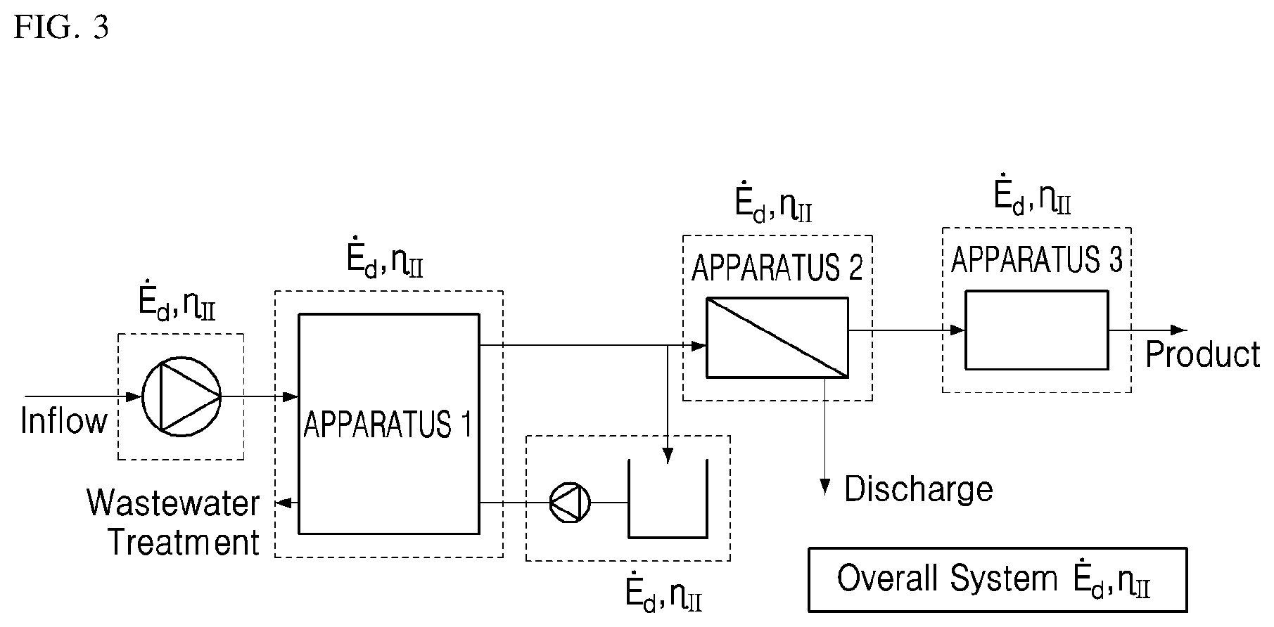
[0038] FIG. 3 is a configuration diagram illustrating a plant model operated according to a plant monitoring method according to an exemplary embodiment;
[0039] FIG. 4 is a flowchart illustrating a plant monitoring method according to an exemplary embodiment;
[0040] FIG. 5 is a flowchart illustrating a plant monitoring method according to an exemplary embodiment in a case in which the plant monitoring method is applied to an ultra-filtration/reverse-osmosis (UF/RO) water plant;
[0041] FIG. 6 is a diagram showing an example of chemical exergy and physical exergy;
[0042] FIG. 7 is a diagram showing a basic formula for calculating an exergy efficiency value based on the physical exergy and the chemical exergy of FIG. 6;
[0043] FIG. 8 is a schematic diagram illustrating a method of calculating an exergy value for an apparatus or a subsystem in which only a fluid flow exists;
[0044] FIG. 9 is a schematic diagram illustrating a method of calculating an exergy value of an apparatus or a subsystem including a pump, a turbine and generator, a combustor, or a boiler;
[0045] FIG. 10 is a diagram comparing a related art data table and a data table according to an exemplary embodiment; and
[0046] FIG. 11 is a diagram illustrating an energy saving effect obtained by applying a plant monitoring method according to the exemplary embodiment.
DETAILED DESCRIPTION
[0047] Various modifications and various embodiments will be described in detail with reference to the accompanying drawings so that those skilled in the art can easily carry out the disclosure. It should be understood, however, that the various embodiments are not for limiting the scope of the disclosure to the specific embodiment, but they should be interpreted to include all modifications, equivalents, and alternatives of the embodiments included within the spirit and scope disclosed herein.
[0048] The terminology used herein is for the purpose of describing specific embodiments only and is not intended to limit the scope of the disclosure. The singular expressions "a", "an", and "the" are intended to include the plural expressions as well, unless the context clearly indicates otherwise. When an element is referred to as being "on" another element, it can be directly on the other element or intervening elements may be present therebetween.
[0049] In the disclosure, the terms such as "comprise", "include", "have/has" should be construed as designating that there are such features, regions, integers, steps, operations, elements, components, and/or combinations thereof, not to exclude the presence or possibility of adding of one or more of other features, regions, integers, steps, operations, elements, components, and/or combinations thereof.
[0050] Further, terms such as "first," "second," and so on may be used to describe a variety of elements, but the elements should not be limited by these terms. The terms are used simply to distinguish one element from other elements. The use of such ordinal numbers should not be construed as limiting the meaning of the term. For example, the components associated with such an ordinal number should not be limited in the order of use, placement order, or the like. If necessary, each ordinal number may be used interchangeably.
[0051] FIG. 3 is a block diagram illustrating a construction of a plant model operated by a plant monitoring method according to an exemplary embodiment, FIG. 4 is a flowchart illustrating a plant monitoring method according to an exemplary embodiment, and FIG. 5 is a flowchart illustrating a plant monitoring method according to an exemplary embodiment in a case in which the plant monitoring method is applied to an ultra-filtration/reverse-osmosis (UF/RO) water plant.
[0052] Referring to FIGS. 3 to 5, a plant monitoring method S100 of monitoring a plant in which two or more apparatuses or subsystems constitute a single system may include a data detection step S110, an exergy efficiency value calculation step S120, a maintenance target identification step S130, and a maintenance time calculation step S140.
[0053] The data detection step S110 is an operation of detecting data related to a chemical exergy and a physical exergy from each apparatus and each subsystem. Here, a chemical exergy value E.sup.CH and a physical exergy value E.sup.PH for each apparatus and each subsystem may be obtained on the basis of the detected data.
[0054] The data detection step S110 is preferably repeatedly performed on a regular cycle. The data collected through the data detection step may be averaged over a predetermined period of time and resulting values may be recorded as data in a recording medium. The recorded data may be used in subsequent steps. The period of time over which the data is averaged may vary depending on apparatus or subsystem. Also, it may vary depending on environmental conditions. For example, the period of time may be appropriately set according to a temperature, humidity, precipitation, snowfall, wind speed, and season in the area in which the apparatus or the subsystem is installed.
[0055] The exergy efficiency value calculation step S120 is an operation of calculating the exergy efficiency values .eta..sub..PI. of respective apparatuses and subsystems on the basis of the detected data.
[0056] FIG. 6 is a diagram illustrating an example of chemical exergy and physical exergy, and FIG. 7 shows basic equations for calculating the exergy efficiency values on the basis of the concept of FIG. 6.
[0057] Referring to FIGS. 6 and 7, the exergy values that can be obtained through the data detection step S110 include a chemical exergy value E.sup.CH and a physical exergy value E.sup.PH. The chemical exergy value E.sup.CH is calculated by Equation 1, the physical exergy value E.sup.PH is calculated by Equation 2, and the total exergy value is calculated by Equation 3.
i = 1 n y i ( .mu. i * - .mu. i 0 ) Equation 1 v 2 2 + g ( l - l * ) + ( h - h * ) - T 0 ( s - s * ) Equation 2 v 2 2 + g ( l - l * ) + ( h - h * ) - T 0 ( s - s * ) + i = 1 n y i ( .mu. i * - .mu. i 0 ) Equation 3 ##EQU00002##
[0058] In these equations, v is a flow velocity value, g is a gravitational acceleration value, l is a level value, h is a specific enthalpy value, s is a specific entropy value, y is a specific mass fraction value, and .mu. is a specific chemical potential value.
[0059] In some cases, the chemical exergy value E.sup.CH may be calculated by Equation 4, the physical exergy value E.sup.PH may be calculated by Equation 5, and a standard chemical exergy value e.sub.k.sup.CH of a component k may be calculated by Equation 6.
E.sup.CH=.SIGMA.x.sub.ke.sub.k.sup.CH+{dot over (R)}T.sub.0.SIGMA.x.sub.k ln x.sub.k Equation 4
E.sup.PH=(U-U.sub.0)+p.sub.0(V-V.sub.0)-T.sub.0(S-S.sub.0) Equation 5
e.sub.k.sup.CH=-{dot over (R)}T.sub.0 ln x.sup.e.sub.k Equation 6
[0060] In these equations, U, V, and S are internal energy of each system, volume, and entropy, respectively, a superscript of 0 denotes a reference environment, the component x.sub.k is a molar fraction value of a component k, {dot over (R)} is a gas constant, and x.sup.e.sub.k is a mole fraction value of the component k in the reference environment.
[0061] In this case, the exergy efficiency value .eta..sub..PI. is a sum of the chemical exergy value E.sup.CH and the physical exergy value E.sup.PH, and the chemical exergy value E.sup.CH preferably includes a mixing exergy value.
[0062] FIG. 8 is a schematic diagram illustrating a method of calculating an exergy value of an apparatus or subsystem in which only a fluid flow exists.
[0063] Referring to FIG. 8, the exergy value of the apparatus or subsystem can be calculated from the total exergy that is input to the apparatus or subsystem and the total exergy that is output from the apparatus or subsystem.
[0064] FIG. 9 is a schematic diagram illustrating a method of calculating an exergy value of an apparatus or subsystem including a pump, a turbine and generator, a combustor, or a boiler.
[0065] Referring to FIGS. 8 and 9, in the exergy efficiency value calculation step S120, if there is a stream to which electric energy and chemical energy are input or a stream from which electrical energy and chemical energy are generated or output in addition to the flow applied to the plant, it is preferable to calculate the exergy efficiency value by reflecting data associated with the stream.
[0066] FIG. 10 is a table in which an efficiency of each apparatus or subsystem is represented in a form of a value within a range of 0 to 1 when the method according to the exemplary embodiment is used.
[0067] Referring to FIG. 10, it can be aware of the efficiency value for each factor in each apparatus or subsystem A to L. Therefore, it is possible even for workers who are not sufficiently experienced or do not have sufficient knowledge about facilities in the plant to understand the operation efficiency of each facility.
[0068] The maintenance target identification step S130 refers to an operation of identifying an apparatus or subsystem that needs to be improved in efficiency on the basis of the data acquired through the exergy efficiency value calculation step 120.
[0069] The maintenance target identification step S130 may include first, second, and third sub-steps S131, S132, and S133.
[0070] The first sub-step S131 of the maintenance target identification step S130 is an operation of detecting an apparatus or subsystem having a data value that is out of a predetermined normal range and of determining the detected apparatus or subsystem as an apparatus or subsystem that needs to be improved in efficiency. The apparatus or subsystem that needs to be improved in efficiency will be referred to as "maintenance target". The second sub-step S132 of the maintenance target identification step S130 is an operation of checking for the maintenance priority of each apparatus and each subsystem. The third sub-step S133 of the maintenance target identification step S130 is an operation of ordering the apparatuses or subsystems that are determined as the maintenance targets in the first sub-step S131 according to the priorities confirmed in the second sub-step S132.
[0071] Through the sub-steps S131, S132, and S133 of the maintenance target identification step S130, it is possible to effectively manage each of the apparatuses or subsystems that need to be improved according to the predetermined maintenance priority order.
[0072] The maintenance time calculation step S140 refers to an operation of calculating a time at which each apparatus or subsystem is to be maintained or improved on the basis of the data obtained through the exergy efficiency value calculation step 120.
[0073] The maintenance target identification step S140 may include fourth, fifth, and sixth sub-steps S141, S142, and S143.
[0074] The maintenance time calculation step S140 refers to an operation of estimating a time at which the efficiency of each apparatus or subsystem is expected to be lower than a predetermined efficiency on the basis of each of the exergy efficiency values of various factors, which are derived from data accumulated through the maintenance target identification step 130, thereby determining a time and a cycle on which overall maintenance of each apparatus or system needs to be performed.
[0075] The fourth sub-step S141 of the maintenance time calculation step S140 refers to an operation of storing data sorted by date and time. The fifth sub-step S142 of the maintenance time calculation step S140 is an operation of deriving an operation trend curve associated with the operation efficiency of each apparatus or subsystem on the basis of the data acquired in the fourth sub-step S141. The sixth sub-step S143 of the maintenance time calculation step S140 refers to an operation of deriving the maintenance time and the maintenance cycle on which each apparatus or subsystem needs to be maintained on the basis of the results of the fifth sub-step S142.
[0076] Through the fourth to sixth sub-steps S141, S142, and S143 of the maintenance time calculation step S140, it is possible to accurately determine the time and cycle on which each apparatus or subsystem needs to be maintained, thereby maximizing the overall operation efficiency of the plant and dramatically reducing the cost of maintenance of the plant.
[0077] Depending on conditions, in the plant monitoring method S100 according to an exemplary embodiment, the data detection step S110, the exergy efficiency value calculation step S120, and the maintenance target identification step 130 may be performed again after maintenance for the apparatuses or subsystems determined in the previous maintenance target identification step 130 is performed (operation S150).
[0078] In this case, the operation status of each apparatus or subsystem can be continuously monitored.
[0079] The plant monitoring method S100 may further include a plant diagnosis result output step S160. The plant diagnosis result output step S160 refers to an operation of notifying a plant operator of the apparatus or subsystem identified in the maintenance target identification step S130 and the calculation results of the maintenance time calculation step S140.
[0080] FIG. 11 is a diagram showing an energy saving effect obtained by applying the plant monitoring method according to an exemplary embodiment to a plant.
[0081] Referring to FIGS. 4, 5, and 11, the plant monitoring method S100 may include the data detection step S110, the exergy efficiency value calculation step S120, the maintenance target identification step S130, and the maintenance time calculation S140. Therefore, the plant monitoring method according to an exemplary embodiment has advantages of solving problems with conventional technologies, checking the status of each apparatus or subsystem constituting a plant, and accurately determining the maintenance time and cycle for each apparatus or subsystem.
[0082] As can be seen from FIG. 11, by accurately identifying the apparatuses that need to be improved in efficiency through the plant monitoring method S100 according to the exemplary embodiment, it is possible to remove factor of waste and perform optimum operation, thereby dramatically reducing energy consumption.
[0083] As described above, because the plant monitoring method according to the exemplary embodiment includes the data detection step, the exergy efficiency value calculation step, the maintenance target identification step, and the maintenance time calculation, the plant monitoring method has advantages of solving problems with conventional technologies, being capable of checking the status of each apparatus or subsystem constituting a plant, and accurately determining the maintenance time and cycle for each apparatus or subsystem.
[0084] Meanwhile, various methods according to an exemplary embodiment described above can be implemented in the form of a readable program through various computer means and recorded in a computer-readable recording medium. Herein, the recording medium can include program commands, data files, data structures, etc. alone or in combination thereof. The program commands to be recorded on the recording medium can be those specially designed and constructed for the present disclosure or can also be those known and available to those skilled in the art of computer software. For example, the recording medium can be magnetic media such as hard disks, floppy disks, and magnetic tapes, optical media such as CD-ROMs and DVDs, magneto-optical media such as floptical disks, and hardware devices specially configured to store and execute the program commands such as ROMs, RAMs, and flash memory. Examples of the program commands can include not only machine language wires such as those produced by a compiler but also high-level language wires that can be executed by a computer by using an interpreter, etc. This hardware device can be configured to operate as one or more software modules in order to perform the operation of the present disclosure, and vice versa.
[0085] While exemplary embodiments have been described with reference to the accompanying drawings, it is to be understood by those skilled in the art that various modifications in form and details may be made therein without departing from the sprit and scope as defined by the appended claims. Therefore, the description of the exemplary embodiments should be construed in a descriptive sense and not to limit the scope of the claims, and many alternatives, modifications, and variations will be apparent to those skilled in the art.
* * * * *
D00000
D00001
D00002
D00003
D00004
D00005
D00006
D00007
D00008
D00009
D00010
D00011


XML
uspto.report is an independent third-party trademark research tool that is not affiliated, endorsed, or sponsored by the United States Patent and Trademark Office (USPTO) or any other governmental organization. The information provided by uspto.report is based on publicly available data at the time of writing and is intended for informational purposes only.
While we strive to provide accurate and up-to-date information, we do not guarantee the accuracy, completeness, reliability, or suitability of the information displayed on this site. The use of this site is at your own risk. Any reliance you place on such information is therefore strictly at your own risk.
All official trademark data, including owner information, should be verified by visiting the official USPTO website at www.uspto.gov. This site is not intended to replace professional legal advice and should not be used as a substitute for consulting with a legal professional who is knowledgeable about trademark law.