Mission Configurable Mounting System
Muegerl; Gerard J. ; et al.
U.S. patent application number 16/532479 was filed with the patent office on 2020-03-05 for mission configurable mounting system. The applicant listed for this patent is Spirit of America Corp.. Invention is credited to Thomas D. Gardner, Gerard J. Muegerl.
| Application Number | 20200072581 16/532479 |
| Document ID | / |
| Family ID | 69639728 |
| Filed Date | 2020-03-05 |


View All Diagrams
| United States Patent Application | 20200072581 |
| Kind Code | A1 |
| Muegerl; Gerard J. ; et al. | March 5, 2020 |
MISSION CONFIGURABLE MOUNTING SYSTEM
Abstract
A mounting system alternatively configurable as either a mount for a remotely operated weapon, or as a defensive fighting position, including a container portion and a platform assembly portion disposed within the container portion. The platform assembly portion includes a vertically moveable platform selectively attachable to which is a remotely operated weapon mount or a plurality of ballistic wall and roof panels, and frame members for supporting the panels. A lift mechanism is operably connected to the platform, and the platform is moveable by the lift mechanism from a first vertical position to a second vertical position located above the first vertical position. The mounting system has a fully deployed state in the second vertical position in which either the weapon mount or the defensive fighting position structure is supported by the platform and is disposed above the container portion.
| Inventors: | Muegerl; Gerard J.; (Warsaw, IN) ; Gardner; Thomas D.; (Wharton, NJ) | ||||||||||
| Applicant: |
|
||||||||||
|---|---|---|---|---|---|---|---|---|---|---|---|
| Family ID: | 69639728 | ||||||||||
| Appl. No.: | 16/532479 | ||||||||||
| Filed: | August 6, 2019 |
Related U.S. Patent Documents
| Application Number | Filing Date | Patent Number | ||
|---|---|---|---|---|
| 62714659 | Aug 3, 2018 | |||
| Current U.S. Class: | 1/1 |
| Current CPC Class: | F41H 5/16 20130101; F41A 23/36 20130101; F41A 27/24 20130101; F41G 5/04 20130101; F41A 23/00 20130101; F41A 23/24 20130101; F41H 5/023 20130101; F41G 5/06 20130101; F41H 5/24 20130101 |
| International Class: | F41H 5/24 20060101 F41H005/24; F41H 5/16 20060101 F41H005/16; F41H 5/02 20060101 F41H005/02; F41A 27/24 20060101 F41A027/24; F41G 5/06 20060101 F41G005/06; F41A 23/24 20060101 F41A023/24 |
Claims
1. A mission configurable mounting system alternatively configurable as either a mount for a remotely operated weapon, or as a defensive fighting position comprising ballistic panels, the mission configurable mounting system comprising: a container portion; and a platform assembly portion disposed within the container portion, the platform assembly portion comprising: a vertically moveable platform selectively attachable to which is a mount for a remotely operated weapon or a defensive fighting position structure including a plurality of ballistic wall and roof panels, and frame members for supporting the panels, and a lift mechanism operably connected to the platform, the platform moveable by the lift mechanism from a first vertical position to a second vertical position located above the first vertical position; wherein the mounting system has a fully deployed state in the second vertical position in which either a remotely operable weapon mount or an occupiable defensive fighting position is supported by the platform and is disposed above the container portion.
Description
PRIORITY CLAIM AND CROSS-REFERENCE TO RELATED APPLICATION
[0001] This application claims the benefit, under Title 35, U.S.C. .sctn. 119(e), of U.S. Provisional Patent Application Ser. No. 62/714,659 entitled MISSION CONFIGURABLE MOUNTING SYSTEM, filed Aug. 3, 2018, the disclosure of which in its entirety is incorporated herein by reference.
BACKGROUND
[0002] The present invention relates to portable, containerized systems configurable to provide either a mount for a Common Remotely Operated Weapon Station (CROWS), or a Defensive Fighting Position (DFP) to support differing mission-specific operational needs in the field.
SUMMARY
[0003] The present invention provides, in one form thereof, a Mission Configurable Mounting System (MCMS) alternatively configurable as either a mount for a remotely operated weapon for a Common Remotely Operated Weapon Station (CROWS), or a Defensive Fighting Position (DFP) adapted for occupation by at least one user. The MCMS includes a container portion and a platform assembly portion disposed within the container portion. The platform assembly portion includes a vertically moveable platform selectively attachable to which is a mount for a remotely operated weapon, or a DPF structure including a plurality of ballistic wall and roof panels and frame members for supporting the panels. The MCMS includes a lift mechanism operably connected to the platform, which is moveable by the lift mechanism from a first vertical position to a second vertical position located above the first vertical position. The MCMS has a fully deployed state in the second vertical position. In the fully deployed state, either a remotely operable weapon mount or an occupiable DFP is supported by the platform and is disposed above the container portion.
BRIEF DESCRIPTION OF THE DRAWINGS
[0004] The various objects, features and attendant advantages of the present invention will become fully appreciated as the same becomes better understood when considered in conjunction with the accompanying drawings. Although the drawings represent embodiments of the disclosed apparatus, the drawings are not necessarily to scale or to the same scale and certain features may be exaggerated or omitted in order to better illustrate and explain the present disclosure. Moreover, in accompanying drawings that show sectional views, cross-hatching of various sectional elements may have been omitted for clarity. It is to be understood that this omission of cross-hatching is for the purpose of clarity in illustration only. Herein, the term "rectangular" also means square unless indicated otherwise.
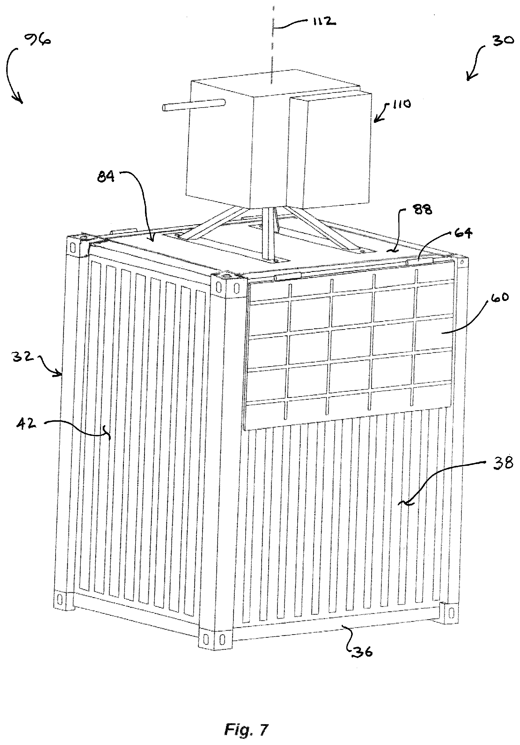
[0005] FIG. 1 is a right rear perspective view of a first embodiment of a Mission Configurable Mounting System (MCMS) according to the present invention configured as a Common Remotely Operated Weapon Station (CROWS) mount, shown in a fully deployed state with no weapon mounted thereto;
[0006] FIG. 2 is an upper right rear perspective view of the MCMS embodiment of FIG. 1 in its fully deployed state;
[0007] FIG. 3 is the MCMS embodiment of FIG. 1, in a closed state, with its hinged top doors closed;
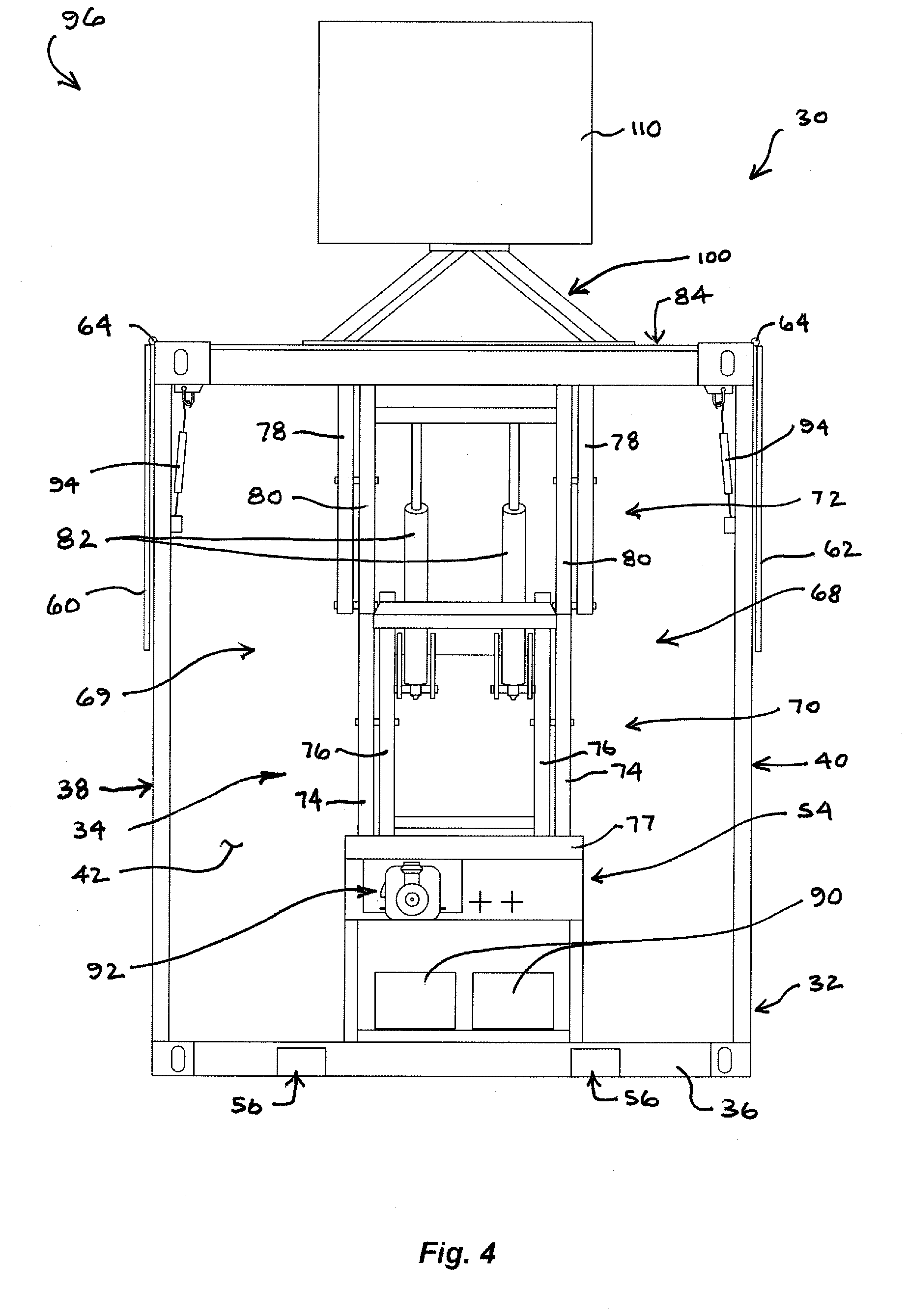
[0008] FIG. 4 is a rear view of the MCMS embodiment of FIG. 1 in its fully deployed state, with the container access doors omitted for clarity, and schematically showing a remotely operable weapon mounted thereto;
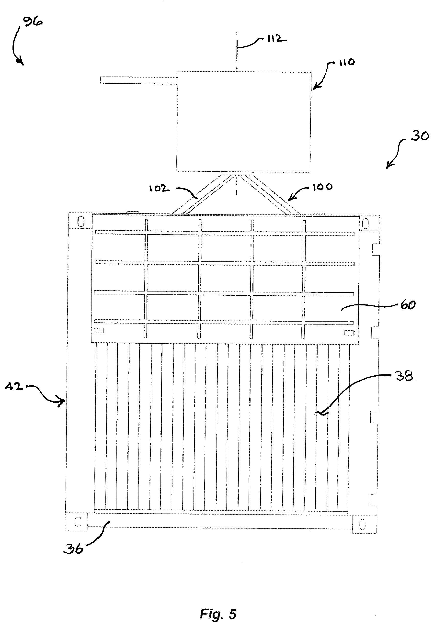
[0009] FIG. 5 is a left side view of the MCMS embodiment of FIG. 4;
[0010] FIG. 6 is an upper right rear perspective view of the MCMS embodiment of FIG. 4;
[0011] FIG. 7 is an upper left front perspective view of the MCMS embodiment of FIG. 4;
[0012] FIG. 8 is a left side view of a first embodiment MCMS configured to provide a CROWS mount in its fully deployed state, with a remotely operable weapon mounted thereto, the depicted MCMS including or, alternatively, shown secured to, a load lifting and transporting trailer attachable to a tow vehicle;
[0013] FIG. 9 is a right front perspective view of MCMS according to the first embodiment in its fully closed state, the depicted MCMS including or, alternatively, shown secured to, a transport trailer attachable to a tow vehicle for transport;
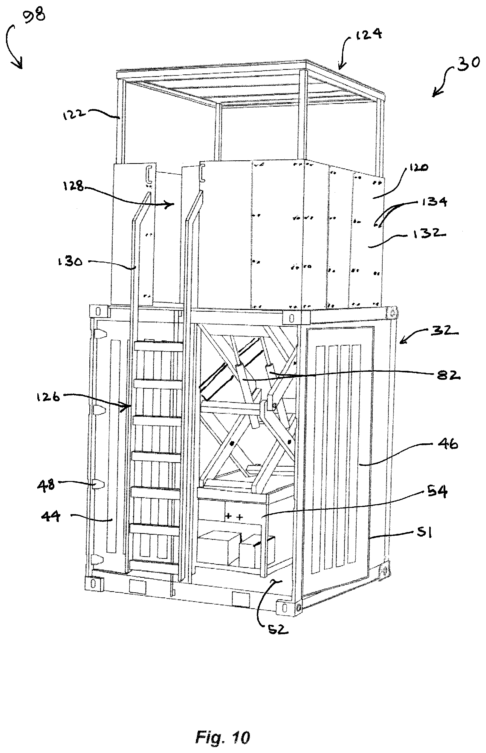
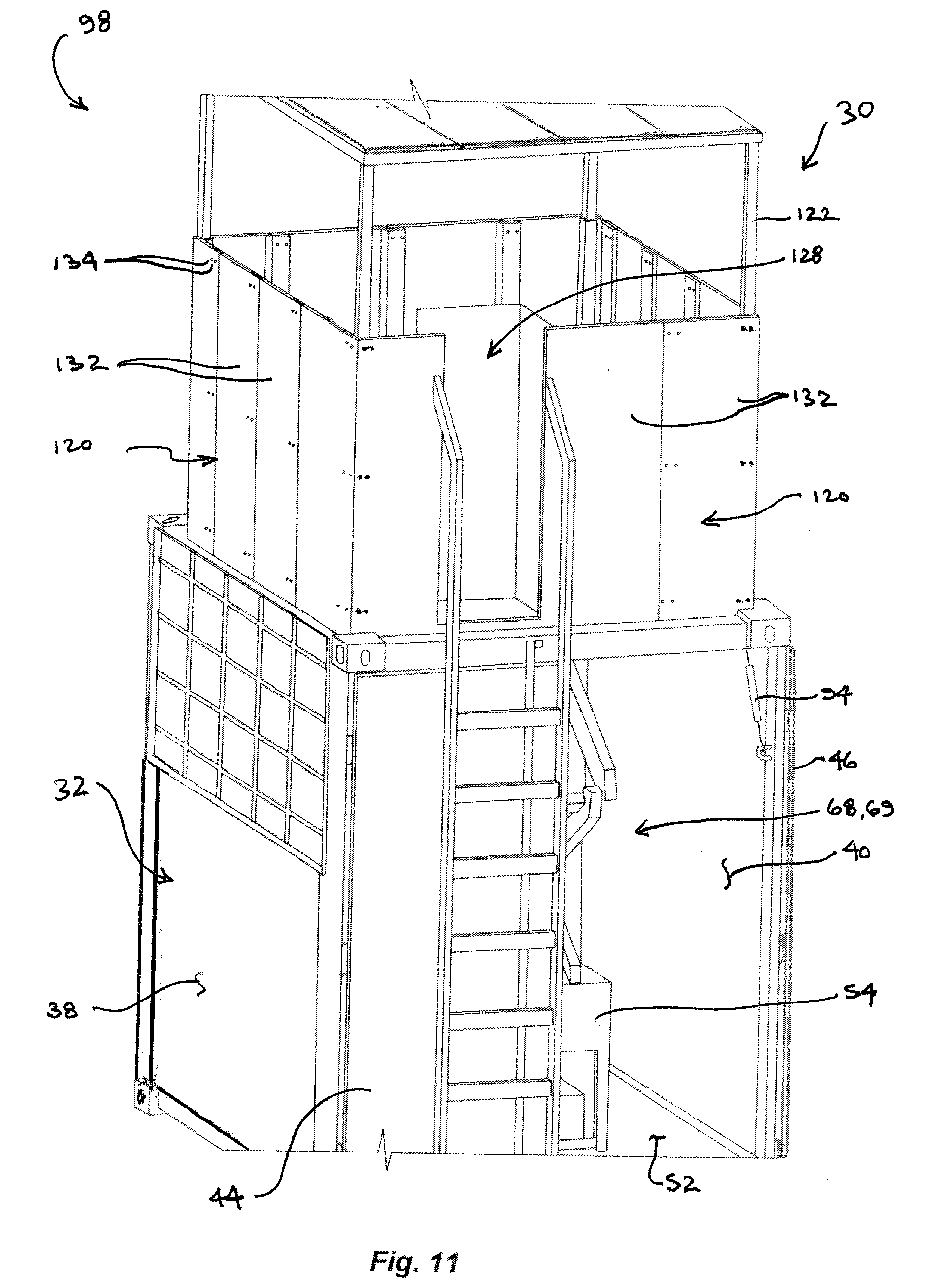
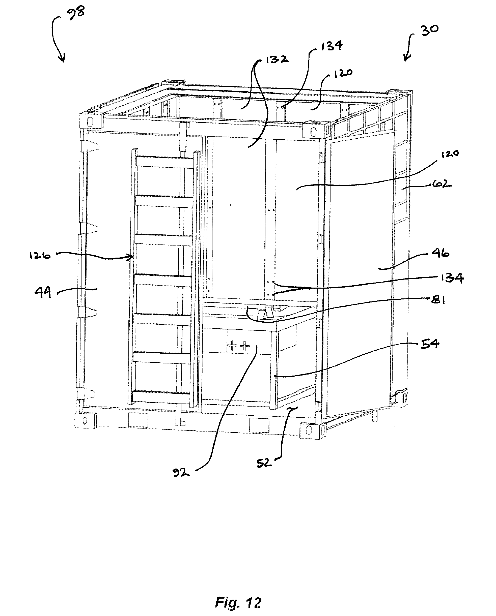
[0014] FIG. 10 is a right rear perspective view of an MCMS according to the first embodiment configured to provide one type of open DFP, and shown in its fully deployed state;
[0015] FIG. 11 is a partial, upper left rear perspective view of the MCMS embodiment of FIG. 10;
[0016] FIG. 12 is an upper right rear perspective view of the MCMS embodiment of FIG. 10 shown in its fully lowered state, without its roof or the roof-supporting stanchions and overhead frame members attached, or its ladder fully assembled;
[0017] FIG. 13 is another upper right rear perspective view of the MCMS embodiment of FIG. 12 with its roof, roof-supporting stanchions and overhead frame members attached, but without its ladder fully assembled;
[0018] FIG. 14 is a partial, cross sectional rear view of the MCMS embodiment of FIGS. 10 to 13 in its fully deployed state;
[0019] FIG. 15 is a right rear perspective view of an MCMS according to the first embodiment configured to provide one type of enclosed DFP, shown in its fully lowered state with its windowed walls, roof and supporting framework attached;
[0020] FIG. 16 is an upper right rear perspective view of the MCMS embodiment of FIG. 15, shown in its fully deployed state;
[0021] FIG. 17 is an enlarged partial, upper left rear perspective view of the MCMS embodiment of FIG. 16, showing its DFP access door in an open position;
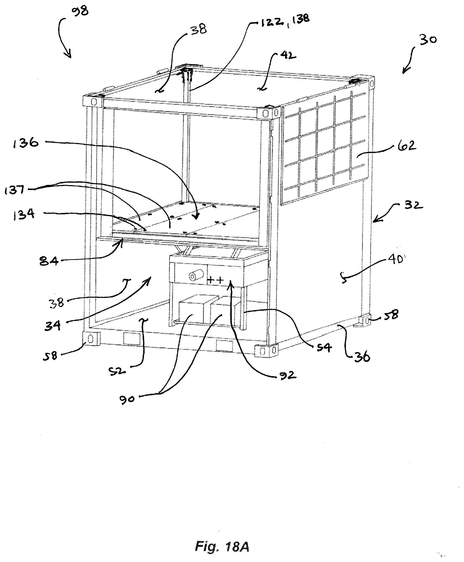
[0022] FIG. 18 (i.e., FIGS. 18A to 18F, collectively) is a series of upper right rear perspective views of an MCMS according to the first embodiment in its fully lowered state, with the container access doors variously omitted for clarity, showing various stages of assembly into the DFP configuration shown in FIGS. 15 and 16;
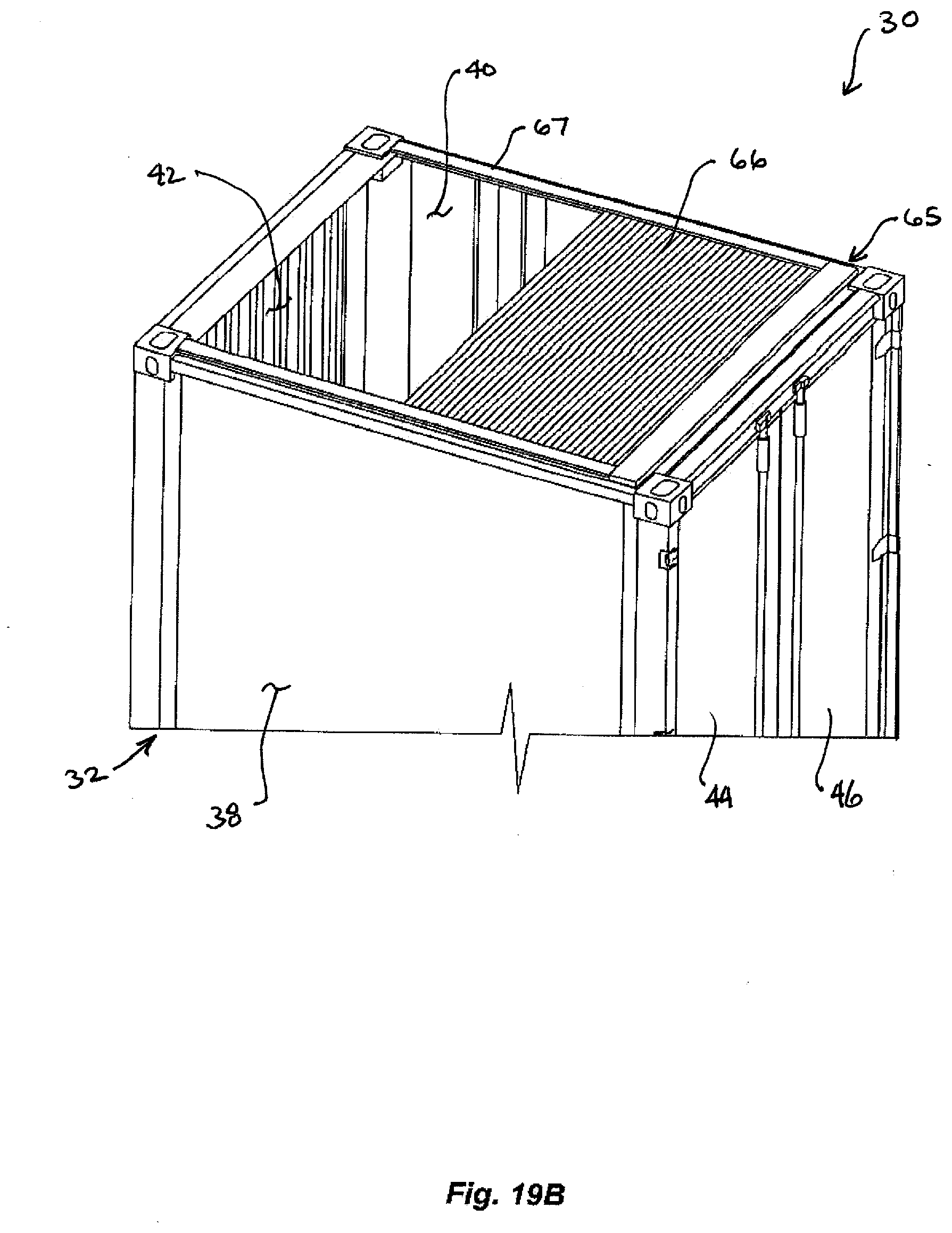
[0023] FIG. 19 (i.e., FIGS. 19A, 19B and 19C, collectively) is a series of views of a retractable cover for the container portion of an MCMS showing the cover in fully closed, partially closed and fully open positions;
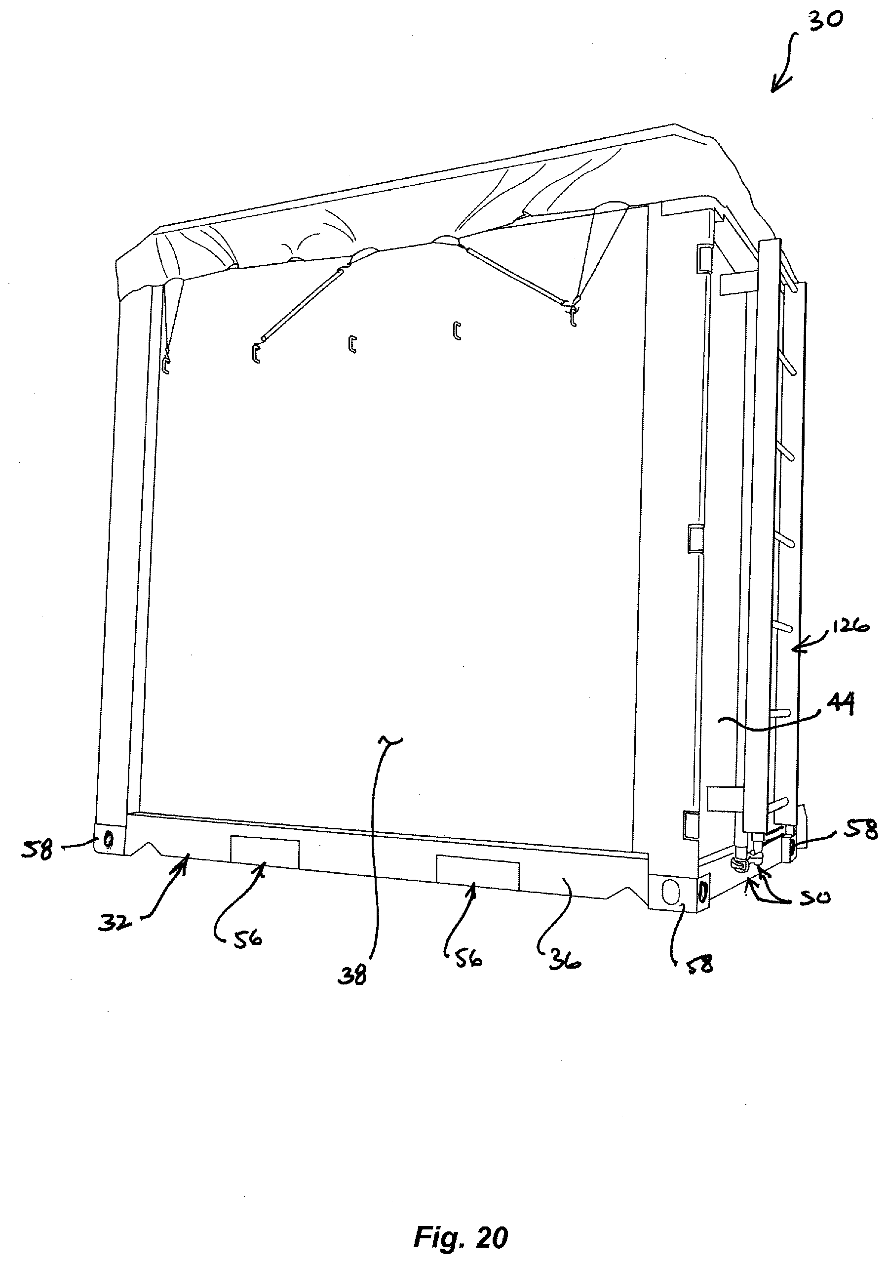
[0024] FIG. 20 is a left perspective view of an MCMS embodiment, the top of the container portion of which is covered by a tarp secured thereto;
[0025] FIGS. 21 to 31 are views of a second MCMS embodiment variously configured as a CROWS mount and/or a DFP.
[0026] Corresponding reference characters indicated corresponding parts throughout the several views. Although the drawings represent embodiments of the disclosed apparatus, the drawings are not necessarily to scale or to the same scale and certain features may be exaggerated in order to better illustrate and explain the present disclosure.
DETAILED DESCRIPTION OF EXEMPLARY EMBODIMENTS
[0027] The disclosed invention is adaptable to various modifications and alternative forms, and the specific embodiments thereof shown by way of example in the drawings is herein described in detail. The exemplary embodiments of the present disclosure are chosen and described so that others skilled in the art may appreciate and understand the principles and practices of the present disclosure. It should be understood, however, that the drawings and detailed description are not intended to limit the invention to the particular forms disclosed, but on the contrary, the intention is to cover all modifications, equivalents and alternatives falling within the spirit and scope of the present invention as defined by the appended claims.
[0028] MCMS 30 generally comprises, in each of its various embodiments, container portion 32 and platform assembly portion 34 enclosed within and carried by container portion 32. Container portion 32 of MCMS 30 is generally cuboid, and of a type and construction known in the relevant art, for example, a Tri-con (8' long.times.6.5' wide.times.8' tall) container. Container portion 32 has a steel frame of interconnected tubular members of rectangular cross-section, that generally defines a parallelepiped. The interior space of container portion 32 is defined by a horizontal floor and the interior surfaces of vertical sides, which in certain embodiments are all formed from low carbon sheet steel.
[0029] Container portion 32 includes base 36 that substantially lies in a horizontally-extending plane; vertically-extending left sidewall 38, right sidewall 40, front sidewall 42, and adjacent rear sidewalls defined by left container access door 44 and right container access door 46 when these doors are in their closed positions. Left and right container access doors 44 and 46 are pivotally attached with hinges 48 to the container frame near the rear edges of left and right sidewalls 38 and 40, respectively. Door latch mechanisms 50 are provided at the rear of the container frame at positions along its top and bottom edges, and on each of left and right container access doors 44 and 46. Door latch mechanisms 50 secure doors 44 and 46 in their closed positions independently of each other and are selectively lockable to prevent access to the interior of container portion 32. Container access doors 44 and 46 are each provided with seals 51 about their respective outer peripheries whereby the interior of container portion 32 is substantially sealed from dust and moisture in either its closed or fully deployed states.
[0030] Base 36 defines a generally rectangular footprint of container portion 32 and supports substantially planar floor 52 of the interior space of container portion 32. In MCMS 30 according to a first embodiment, platform assembly portion 34 is disposed on stand 54 affixed to floor 52 as shown in FIGS. 1 to 4, whereby platform assembly portion 34 is elevated from floor 52. In MCMS 30 according to a second embodiment, platform assembly portion 34 is disposed on and affixed to floor 52 itself, as shown, for example, in FIGS. # to #. The first and second embodiments of MCMS 30 are configurable to provide the CROWS mount and DFP variants described herein.
[0031] The parallel, tubular steel front and rear members of rectangular container portion base 36 is provided with spaced apertures 56 in the front and rear members, for receiving the tines of, for example, a forklift, for moving or supporting the MCMS 30. The eight corners of container portion 32 are provided with receptacles 58 for receiving twist locks of a known type, whereby the container portions 32 of a plurality of MCMS units may be retained to each other in a stacked configuration, if desired, or an MCMS 30 may be retained to a trailer either temporarily for transport, or indefinitely with the trailer comprising part of the MCMS as described further below.
[0032] Referring to FIG. 3, certain MCMS embodiments have a closed state in which container portion 32 has a top surface defined by left container lid 60 and right container lid 62 in their closed positions. Lids 60, 62, which may, for example, be molded of a suitable plastic material, are respectively attached to left and right sides 38 and 40 of container portion 32 by hinges 64. In some such embodiments, the top surface of container portion 32 defined by closed lids 60, 62 is substantially flat and planar.
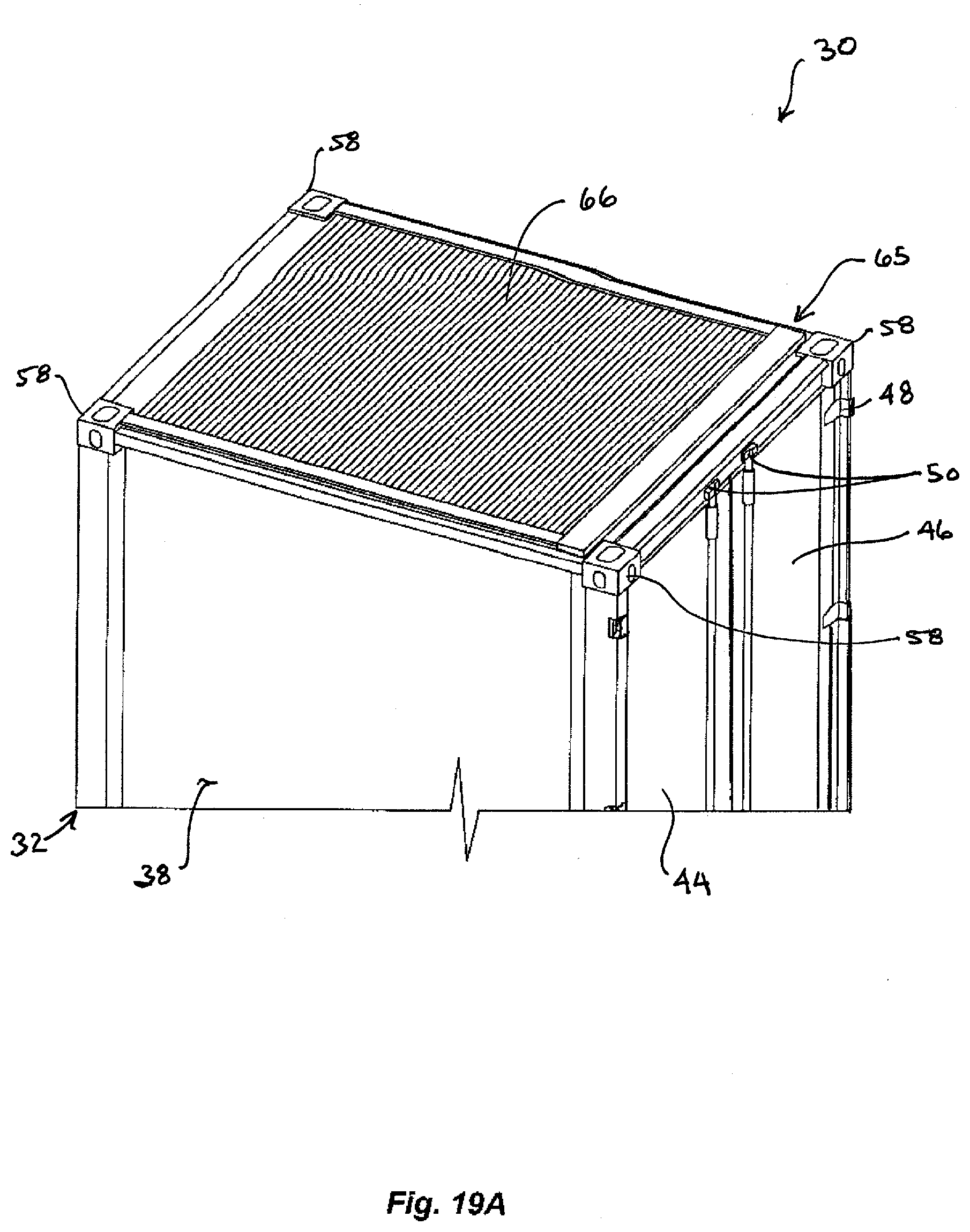
[0033] Referring to FIG. 19, certain other MCMS embodiments have a closed state in which container portion 32 has a top surface defined by retractable door assembly 65 in its closed position (FIG. 19A). Retractable door assembly 65 includes flexible door 66 whose laterally opposite edges are slidably engaged with interfacing track openings in laterally opposite rails of frame 67 having a box into which door 66 is receivable. Door 66 is longitudinally moveable between its fully closed position (FIG. 19A), and its fully open position (FIG. 19C). In its open positions (FIGS. 19B and 19C), at least a portion of door 66 has a spiral-shaped longitudinal cross-sectional shape within the box of frame 67. Door 66 and frame 67 of retractable door assembly 65 may be made of aluminum, with door 66 comprising a plurality of hingedly interconnected slat members. Alternatively, door 66 may be a flexible plastic extrusion comprising pluralities of integrally-formed, laterally-extending slat portions and interposed living hinge portions.
[0034] Still other MCMS embodiments have a closed state in which container portion 32 has a top surface defined by top side 88 of platform 84 in its fully elevated position, a DFP roof with the platform in its fully lowered position (see, e.g., FIG. #), or a tarp secured to container portion 32 (see, e.g., FIG. 20).
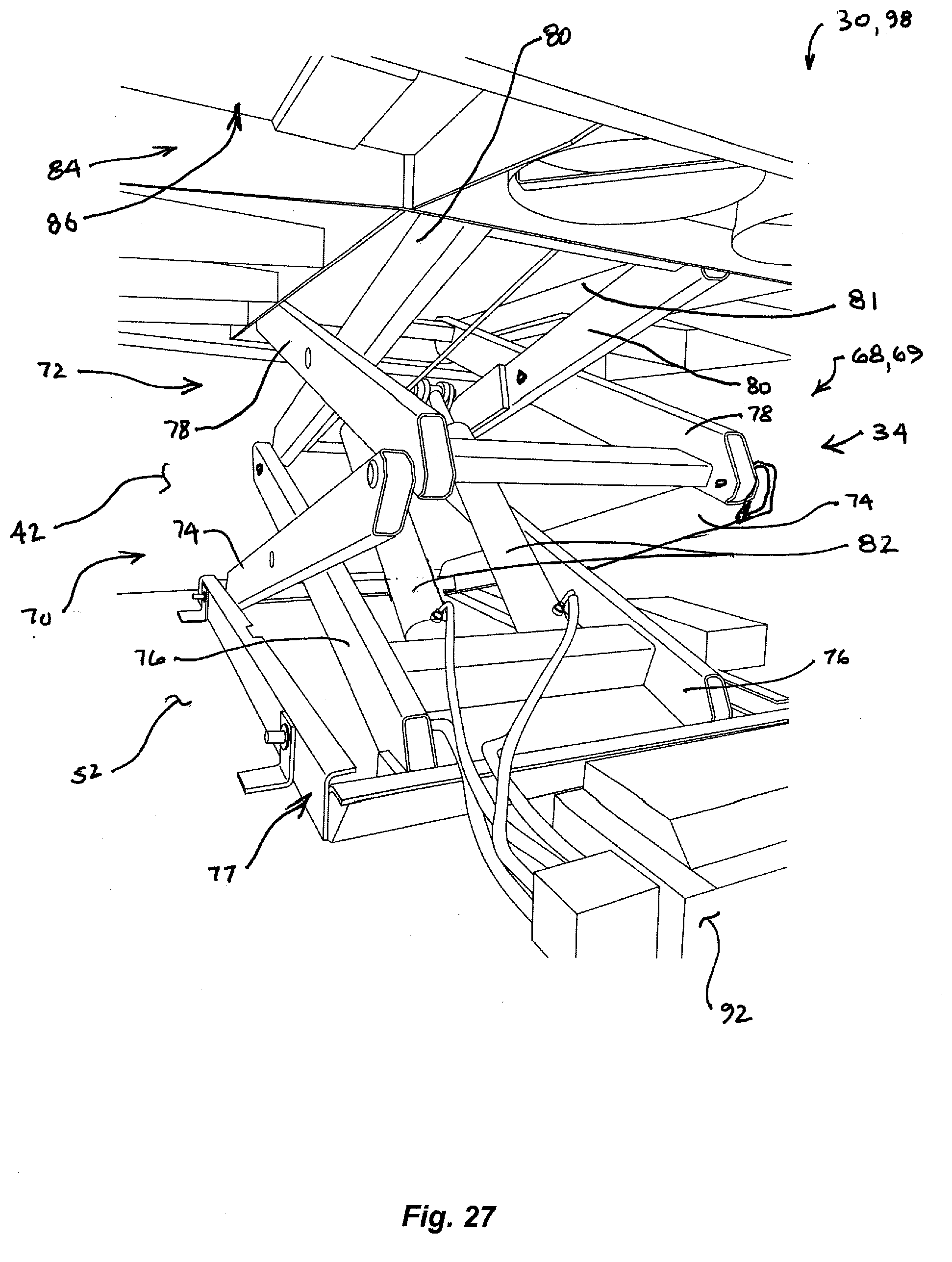
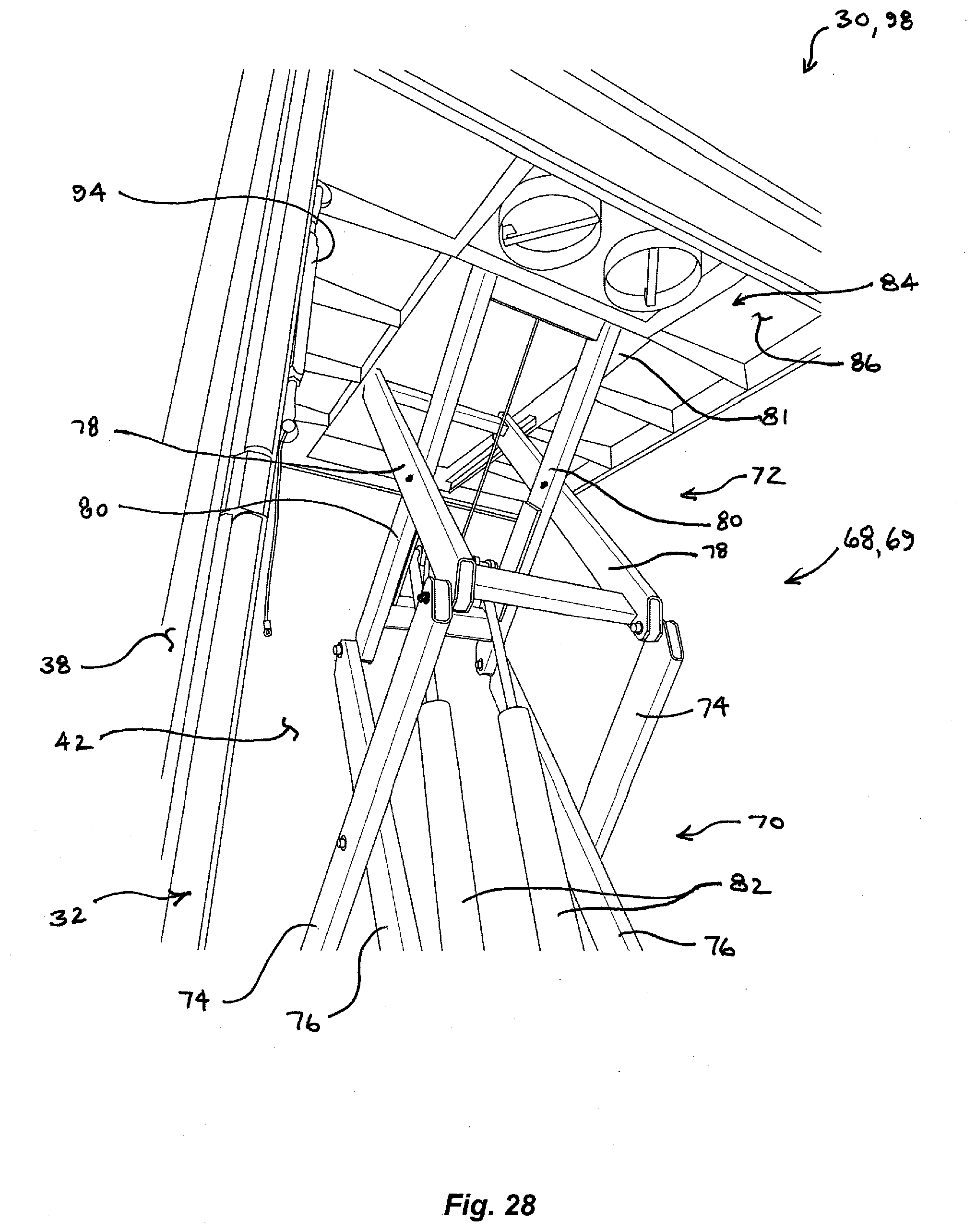
[0035] Platform assembly portion 34 includes lift mechanism 68 which, in certain MCMS embodiments includes scissor jack assembly 69. Scissor jack assembly 69 includes lower half 70 and interconnected upper half 72. Lower half 70 of scissor jack assembly 69 includes a first pair of elongate, rigid, laterally-spaced, parallel arms 74, a second pair of elongate, rigid, laterally-spaced, parallel arms 76, and a rectangular bottom frame 77. In MCMS 30 according to its first embodiment, frame 77 is affixed to stand 54 (FIGS. 1 to 4); in MCMS 30 according to its second embodiment, frame 77 is affixed to container portion floor 52 (FIGS. # to #). Each scissor jack assembly arm 74 of the first pair is pivotally connected to a cooperating scissor jack assembly arm 76 of the second pair near their respective longitudinal midpoints.
[0036] Upper half 72 of scissor jack assembly 69 includes a third pair of elongate, rigid, laterally-spaced, parallel arms 78, a fourth pair of elongate, rigid, laterally-spaced, parallel arms 80, and a rectangular top frame 81. Each arm 78 of the third pair is pivotally connected to a cooperating arm 80 of the fourth pair near their respective longitudinal midpoints. A first terminal end of each arm 74 is pivotally attached to a first terminal end of a cooperating arm 78, and a first terminal end of each arm 76 is pivotally attached to a first terminal end of a cooperating arm 80.
[0037] Scissor jack assembly 69 further includes a pair of linear actuators 82, which in certain embodiments are hydraulic cylinders 82 as shown. Linear actuators 82 extend between and are pivotally connected to the first pair of legs 74 and the fourth pair of legs 80.
[0038] Platform assembly portion 34 of MCMS 30 includes rectangular platform 84 that is moveable by scissor jack assembly 69 between a platform lowermost position and a platform uppermost position. Platform 84 has a bottom side 86 and an opposing top side 88. Top frame 81 of scissor jack assembly 69 is affixed to platform bottom side 86. In certain MCMS embodiments, platform 84 rests on the padded upper ends of stanchions 89 that are generally located in the four corners of container portion 32 and affixed to its floor 52.
[0039] As depicted herein, in certain MCMS embodiments the second terminal end of each arm 74 is rotatable about a fixed pivot point on scissor jack assembly bottom frame 77, and the second terminal end of each arm 80 is rotatable about a fixed pivot point on scissor jack assembly top frame 81. In such embodiments, the second terminal end of each arm 76 is slidably coupled to bottom frame 77, and the second terminal end of each arm 78 is slidably coupled to top frame 81, whereby platform 84 is substantially maintained in a horizontal orientation and in the same fore-aft and lateral positions relative to container portion 32, throughout its range of motion.
[0040] Certain MCMS embodiments include battery 90 for powering hydraulic pump assembly 92, which is operably connected to hydraulic cylinders 82 of scissor jack assembly 69. Hydraulic pump 92 is of a commercially available type known in the art, and includes fluid control valving, an attached hydraulic fluid reservoir, and an electric drive motor selectively powered by battery 90. Hydraulic pump assembly 92 need be activated only to raise platform 84; platform 84 may be lowered by allowing fluid in hydraulic cylinders 82 to return to the reservoir through manipulation of the control valving, in a manner known to one of ordinary skill in the relevant art. In certain unshown MCMS embodiments, linear actuators 82 are electrically, rather than hydraulically, driven and motivated by power received from battery 90 through control circuitry. Some MCMS embodiments include invertor circuitry for converting the DC voltage of battery 90 to AC voltage that is usable by a user of MCMS 30.
[0041] The depicted embodiments of MCMS 30 include turnbuckle assemblies 94 attached near the upper ends of the upright frame members of container portion 32, in its interior corners. Turnbuckles 94 remain secured to container portion 32 and are selectively attached to platform 84 once in its uppermost position, thereby interengaging platform 84 and container portion 32 to secure platform 84 into its uppermost position, at which MCMS 30 is in its fully deployed state configured as either CROWS mount 96 or DFP 98.
[0042] The detailed description provided so far is common to MCMS embodiments regardless of whether configured to provide CROWS mount 96 or DFP 98. Each embodiment of MCMS 30 according to the present invention facilitates the configuration of either one of, or the reconfiguration between, CROWS mount 96 and DFP 98 as desired. Moreover, MCMS 30 is capable of being reconfigured from a CROWS mount 96 to a DFP 98, or vice versa, by an individual using ordinary hand tools, before MCMS 30 is transported to, or while MCMS 30 is located at, its operating site.
[0043] CROWS Mount Configurations.
[0044] As depicted, certain embodiments of MCMS 30 configured as CROWS mount 96 include weapon mount 100 attached to top side 88 of platform 84. Weapon mount 100 includes a plurality of interconnected, elongate legs 102 (four in the depicted embodiments), with the lower ends of legs 102 affixed, as by welds, to a pair of elongate, spaced parallel brackets 104 that are affixed to platform 84 with fasteners 106. Legs 102 converge toward each other in an upward direction such that the upper ends of legs 102 are positioned closer to each other than are their lower ends. The upper ends of legs 102 are affixed, as by welds, to a horizontal plate that forms central mounting hub 108 to which a weapon 110 is rotatably mounted about imaginary vertical axis 112.
[0045] A generic example of weapon 110 is shown schematically in FIGS. 1 to 9 and may be of any type remotely operable utilizing CROWS technology. As depicted in FIGS. 10 to 12, weapon 110 is a belt-fed machine gun having an attached ammunition magazine. MCMS 30 may similarly accommodate a weapon 110 of a different type, such as a missile launcher, for example. By utilizing known CROWS technology, weapon 110 can be aimed, fired or otherwise controlled by an operator located remotely from MCMS 30 configured to provide a CROWS mount and while the MCMS is in its fully deployed state. Hence, MCMS 30 need not be attended by an operator co-located with MCMS 30 other than as required, for example, to deploy, maintain, and/or reload or rearm the mounted weapon 110.
[0046] In certain MCMS embodiments configured as CROWS mount 96, with MCMS 30 in its fully closed state wherein platform 84 is in its lowermost position and, with, for example, container lids 60, 62 or retractable cover 66 closed, mounted weapon 110 may be stored within the interior of container portion 32, entirely enclosed and protected from the elements.
[0047] The MCMS embodiments configured to provide CROWS mounts 96 are of types that are manually deployed by an on-site operator, and whose weaponry 110 is placed under operational control of a remotely-located operator. However, certain other MCMS embodiments configured to provide CROWS mounts 96 are contemplated that are of a type in which the remote operation includes deployment of MCMS 30, i.e., remotely opening the container portion top cover (e.g., left and right container lids 60, 62, retractable cover 66, or a tarp) and moving platform 84 from its lowermost position to its uppermost position and securing the MCMS into its fully deployed state, in addition to operationally controlling its weaponry.
[0048] DFP Configurations.
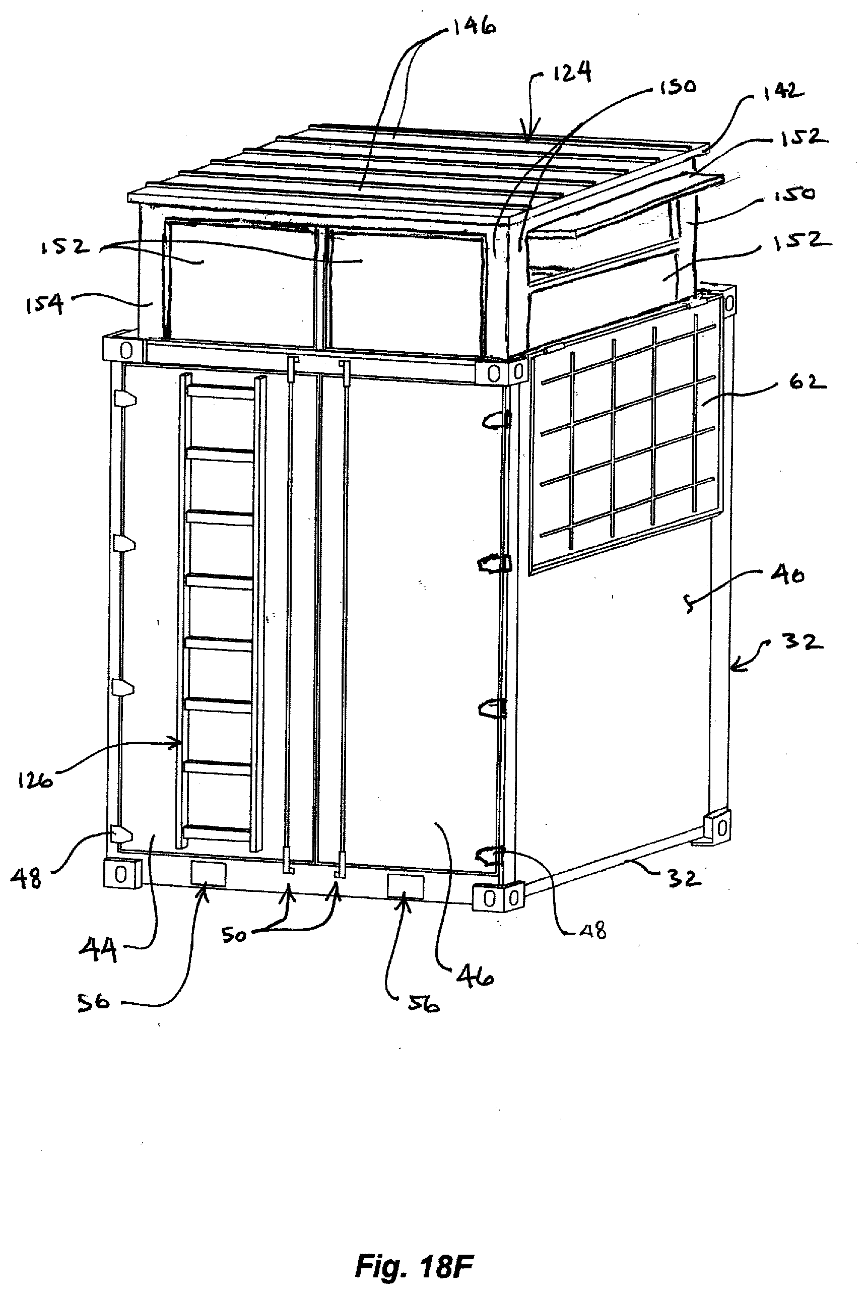
[0049] Referring to FIGS. 10 to 14, certain versions of MCMS 30 according to the first embodiment are configured to provide an open, or window-less version of DFP 98. The depicted MCMS embodiment configured as such a DFP version comprise a plurality of walls 120, stanchions 122, and roof 124. Ladder 126 is attached to the exterior of left container access door 44. Personnel access the space surrounded by walls 120 via ladder 126 and passage 128 located above ladder 126. Walls 120 define passage 128 through which personnel may access the partially enclosed platform. In the depicted embodiment, walls 120 of passage 128 define a 90.degree. passage turn, whereby lines of sight from outside of DFP 98 into the interior DFP space through passage 128 are substantially blocked. Certain other MCMS embodiments providing an open version of DFP 98 provide a hinged ballistic steel door panel (not shown) to close the opening to passage 128 in rear wall 120. Certain DFP configurations include handrails 130 above ladder 126 to help access passage 128 and the interior space within walls 120.
[0050] In certain MCMS embodiments, ladder 126 is temporarily attached to the interior of container access door 44 during storage and transport and is affixed to the exterior of door 44 during deployment of MCMS 30 as shown. In certain other embodiments, ladder 126 is attached to the exterior of container access door 44 at all times.
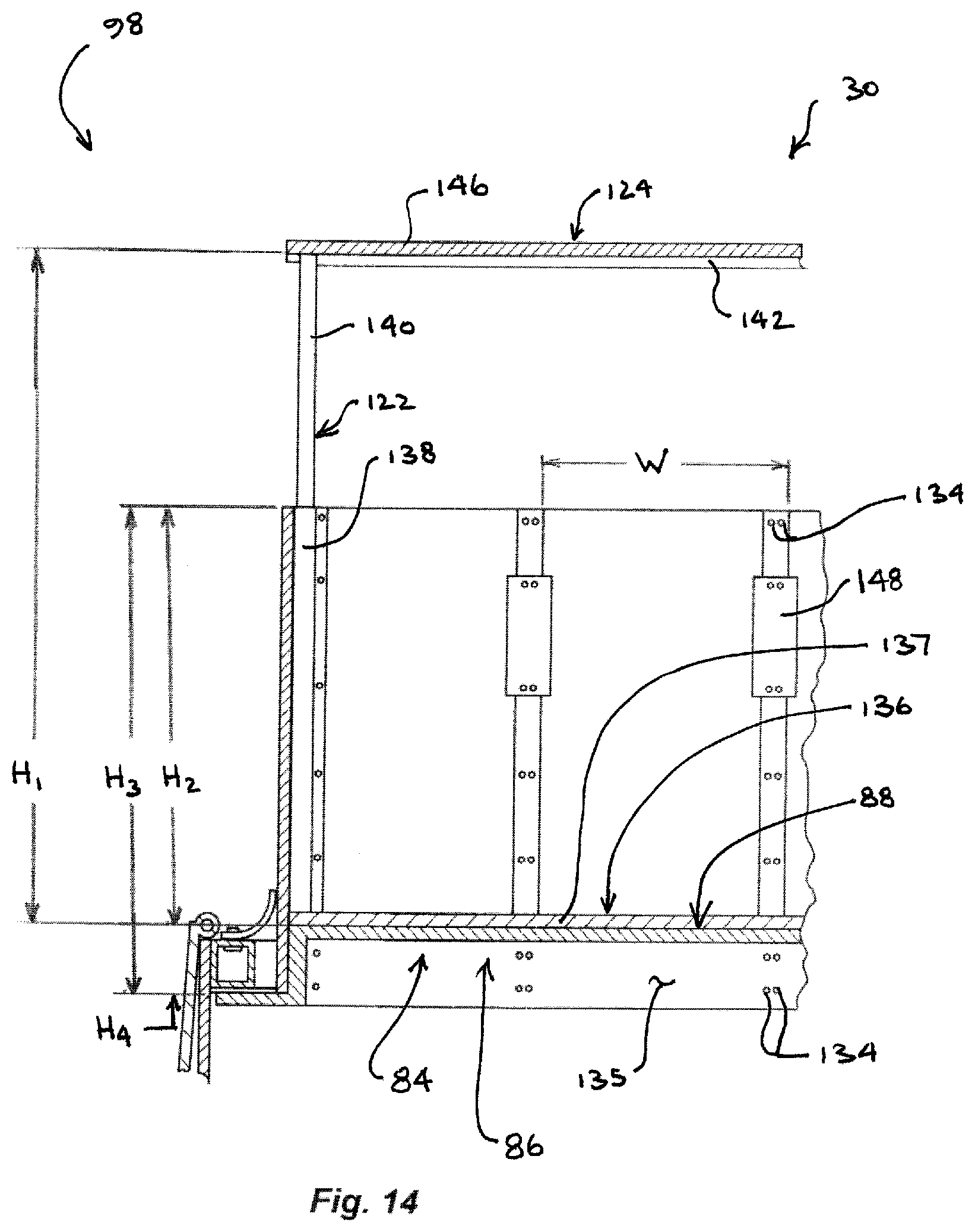
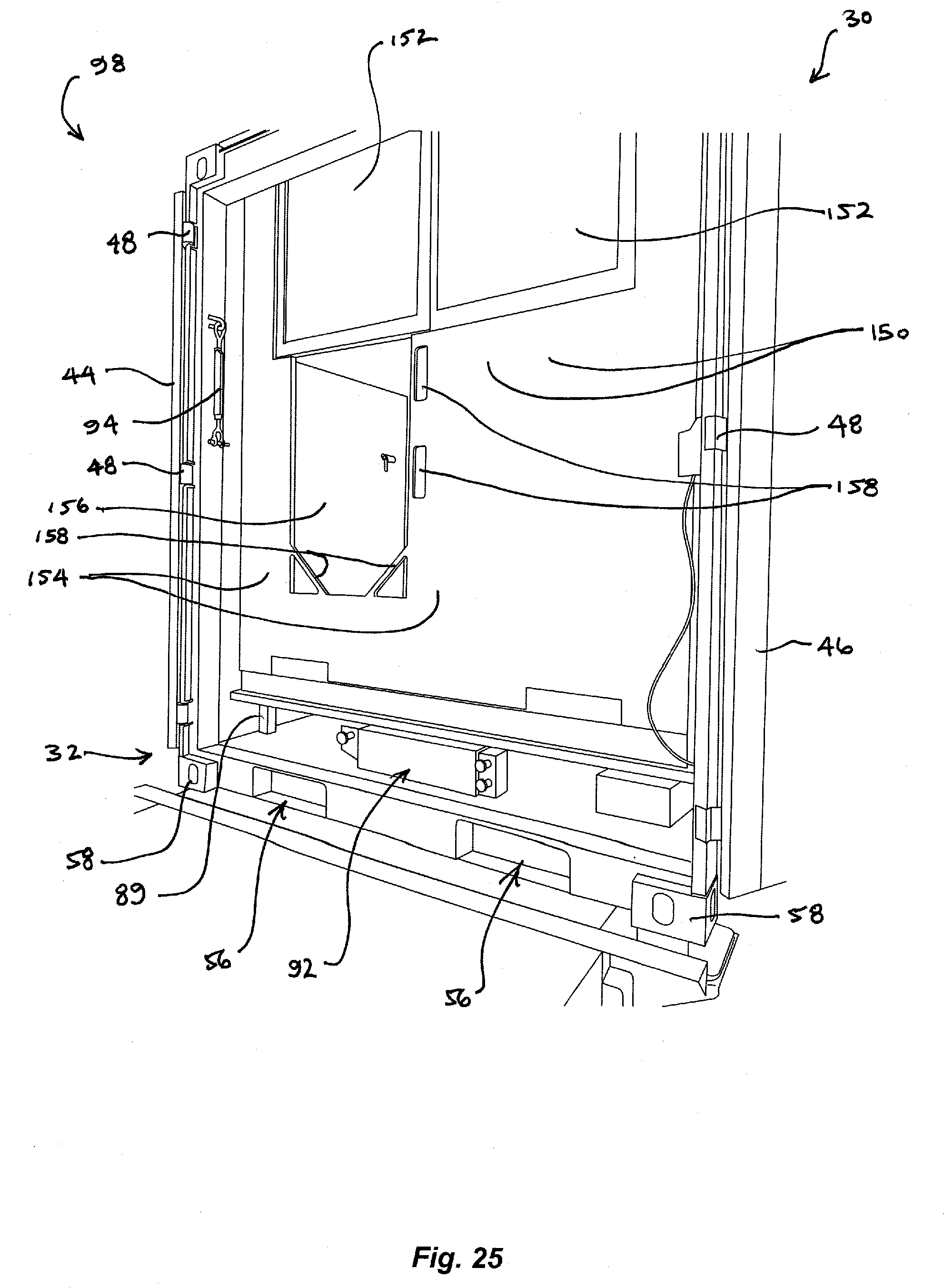
[0051] Walls 120 are formed of a plurality of ballistic steel wall panels 132 that are attached to each other, to stanchions 122, and to platform 84 with fasteners 134. Referring to FIG. 14, substantially planar platform 84 has a substantially hat-shaped cross-section that provides circumferentially-extending vertical surface 135 to which the lowermost portions of wall panels 132 are attached. In certain embodiments, floor 136 of the DFP space within walls 120 is formed by a plurality of contiguous ballistic steel plates 137 that overlay and are attached to top side 88 of platform 84.
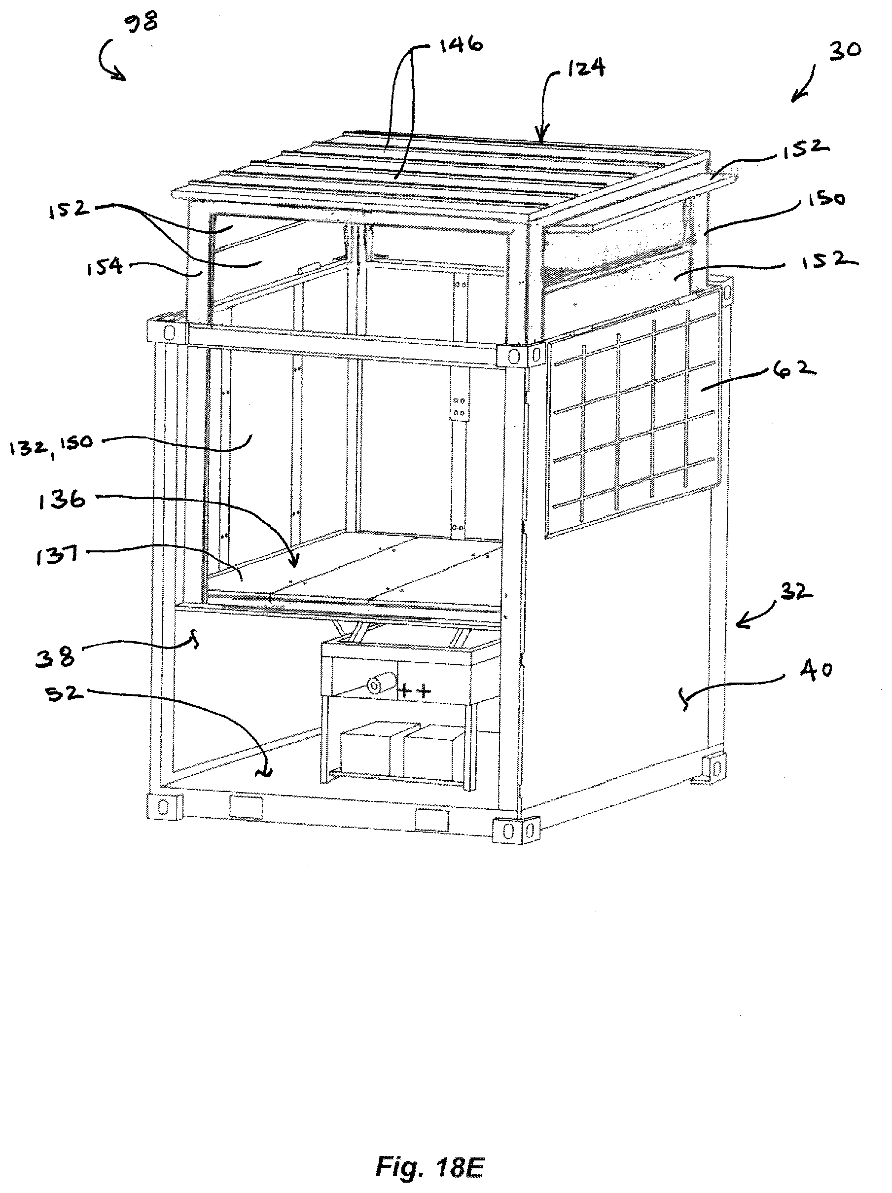
[0052] In certain embodiments, stanchions 122 are positioned in the four interior corners of the DFP space and are telescopic. In such embodiments, each stanchion 122 has an elongate, tubular steel lower portion 138 and an elongate, tubular steel upper portion 140 that is slidably disposed within lower portion 138. During assembly of DFP 98, the lower and upper stanchion portions 138, 140 are slidably extended relative to each other and secured into an extended stanchion configuration. Stanchion upper portions 140 support a corner of a substantially rectangular roof frame 142 defined by four elongate, tubular steel roof frame members that are interconnected at their adjacent terminal ends, thereby forming four corners of DFP roof frame 142. Roof frame 142 supports DFP roof 124, which is formed of a plurality of ballistic steel roof panels 146. Roof panels 146 are affixed to each other and to roof frame 142 with fasteners 134. In certain embodiments, with platform 84 in its lowermost position and portions 138, 140 of telescopically retracted, planar DFP roof 124 is vertically positioned at a height substantially coinciding with the height of the upper edges of the contiguous sidewalls 38, 40, 42 of MCMS container portion 32, and traverses the top opening of container portion 32. In such embodiments, the top surface of DFP roof 124 then defines the top surface of MCMS 30 in its fully closed state, thereby obviating the need for left and right container lids 60, 62. In certain other embodiments, left and right container lids 60, 62 may be closed into superposition with the top surface of DFP roof 124 in the fully closed state of MCMS 30.
[0053] Referring to FIG. 14, in certain MCMS embodiments configured to provide an open version of DFP 98, the overall height between platform top side 88 and telescopically extended roof 124 has a distance H.sub.1; and walls 120 extend above the surface of floor 136 by a distance H.sub.2, which is preferably four (4) feet.
[0054] In such embodiments, each of the plurality of ballistic steel wall panels 132 is elongate and has a vertical length H.sub.3, with the lowermost portions of wall panels 132 attachable with fasteners 134 to a circumferentially extending vertical surface 135 of platform 84 as described above. The width of each ballistic panel 132 is identified in FIG. 14 as width W, though certain of the panels may be of different widths W depending on their location and configuration.
[0055] In certain embodiments, DFP 98 is provided with brackets 148 affixed to the interior surface of wall 120, to which a weapon (e.g., a medium or heavy machine gun) may be mounted and supported at an operable position relative to the upper edge of walls 120.
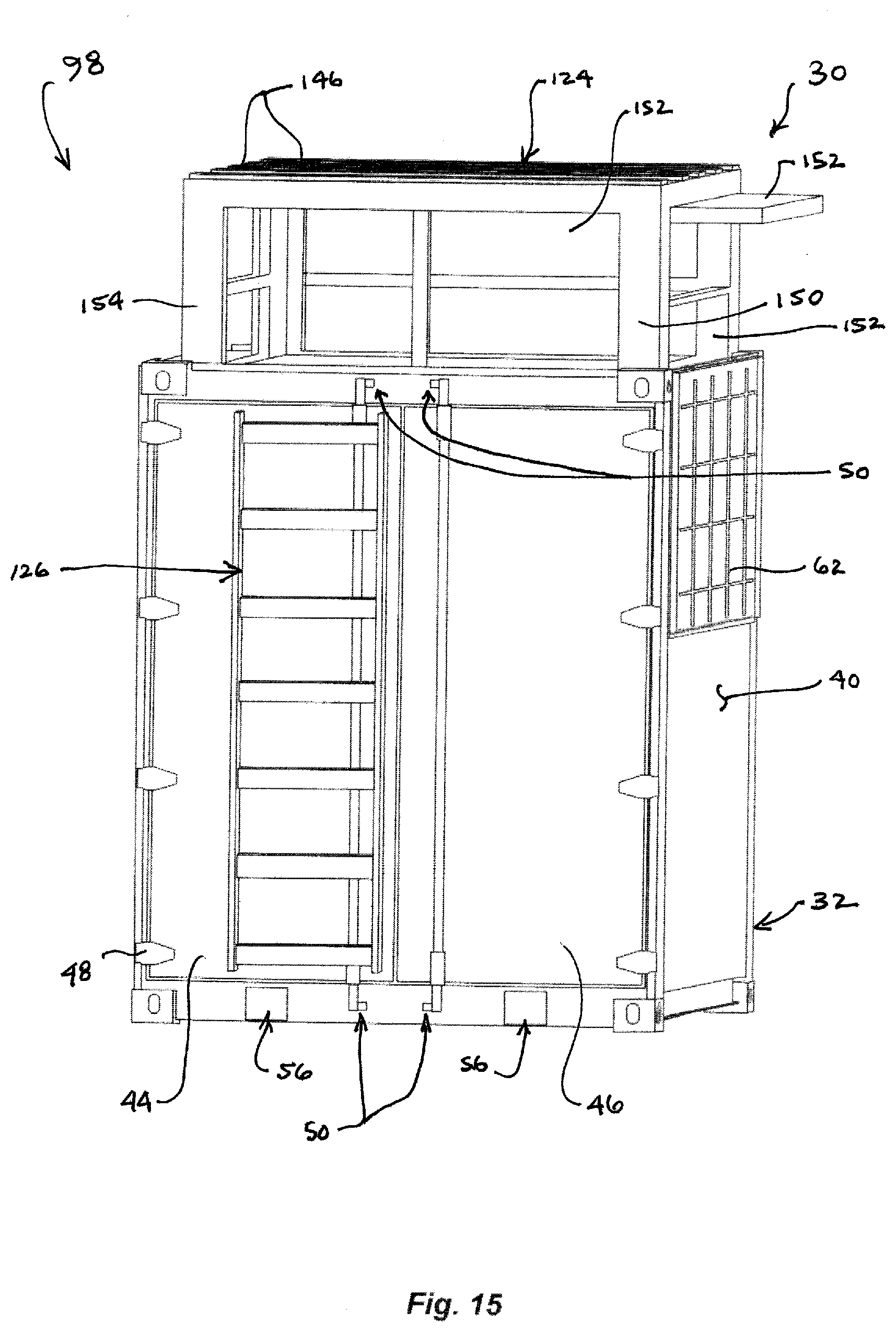
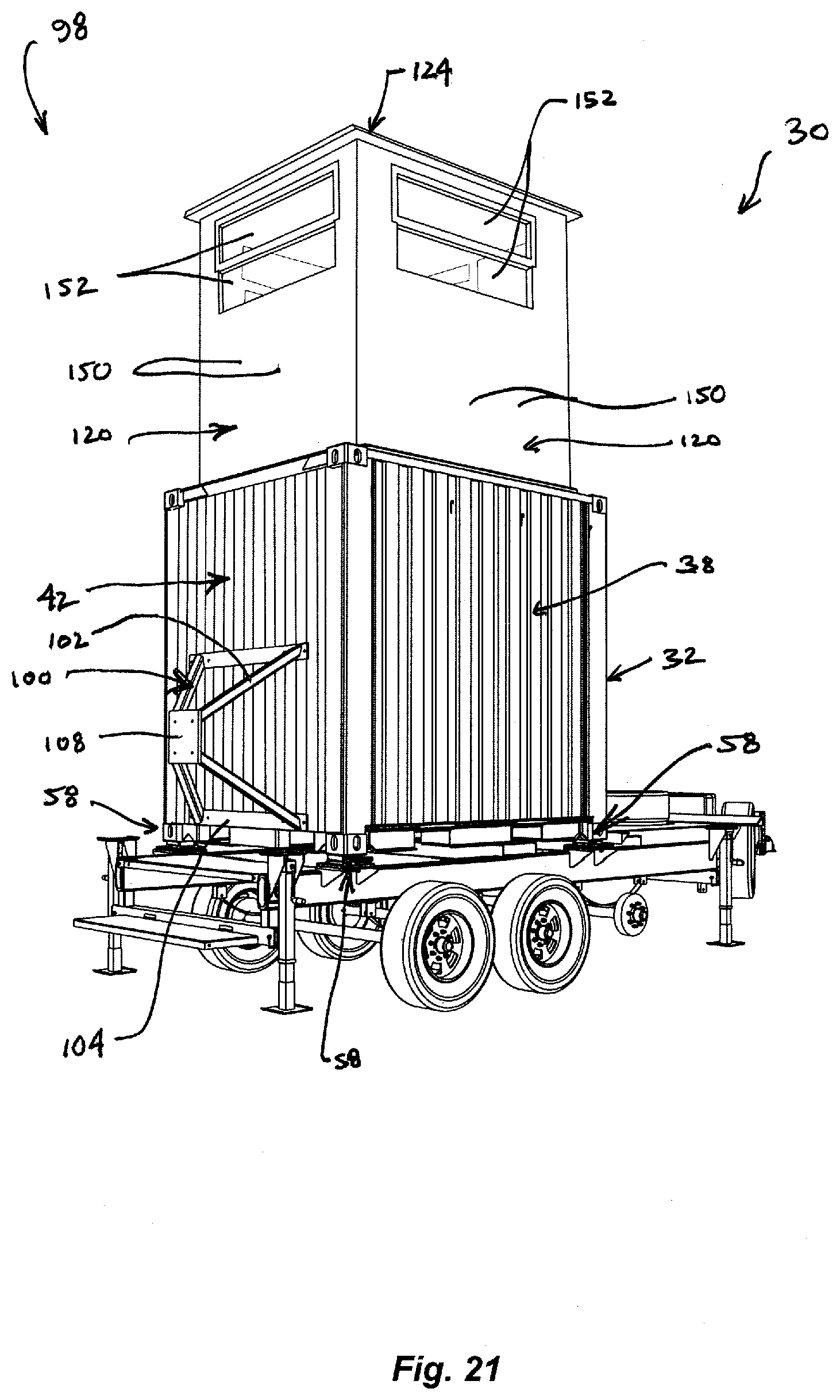
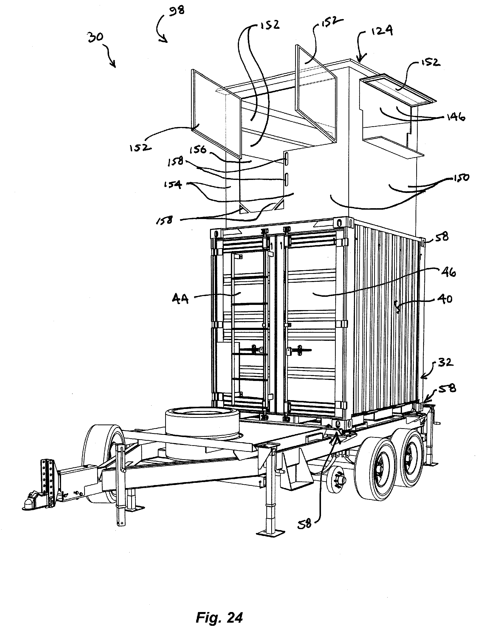
[0056] FIGS. 15 to 18 show a first embodiment MCMS 30 configured to provide an alternative version of DFP 98 that is, other than as herein disclosed, substantially identical in structure, use and function to that of the open version of DFP 98 described above. As shown in FIGS. 15 to 18, DFP 98 has a fully enclosable interior space and is provided with walls 120 formed of interconnected ballistic steel wall panels 150 that that define window frames; the window frames in walls 120 are fitted with ballistic windows 152 of transparent armour panels. Ballistic windows 152 are attached to walls 120 with vertically or horizontally oriented hinges about which windows 152 are openable to facilitate weapon firing from the DFP interior space. In the depicted alternative embodiment of DEP 98, rear wall 120 is formed from interconnected ballistic steel wall panels 154 that define a door frame; the door frame is fitted with latching ballistic steel door 156. In certain embodiments, door 156 is attached to rearward wall 120 with vertically oriented hinges about which door 156 is openable inwardly. In certain embodiments, wall panels 154 are provided with hand grips 158 at the lower corners of the door frame and exclude above-mentioned handrails 130. In certain embodiments, door 156 is provided with one or more handles 160, as shown in FIG. 16. As in the prior DFP embodiment, the floor of the DFP space within walls 120 is formed by a plurality of contiguous ballistic steel plates 137 that overlay platform top surface 88, and roof 124 is formed of a plurality of interconnected ballistic steel roof panels 146 supported by roof frame 142.
[0057] FIGS. 18A to 18F, which collectively comprise FIG. 18, show a series of views of the alternative DFP embodiment of FIGS. 15 to 17 at various stages of assembly. In each of FIGS. 18A to 18F, platform 84 is shown in its lowermost position. In the depicted embodiment of the alternative DFP version, stanchions 122 are not telescopic, but are instead of fixed length, whereby upon attachment of the stanchions during assembly of the DFP, a portion of the DFP projects above the upper edge of container portion 32 as shown in FIGS. 18C to 18F. When MCMS 30 is fully deployed and platform 84 is moved to its uppermost position wherein DFP 98 is positioned substantially as shown in FIGS. 16 and 17, its ballistic steel walls 120 extend above the height of container portion 32.
[0058] Preferably, all ballistic steel panels utilized in all MCMS embodiments configured to provide a DFP meet NIJ Level IV ballistic protection and are sized to facilitate easy handling and assembly by no more than two individuals, and possibly a single individual, acting to assemble or disassemble the DFP during configuration or reconfiguration of MCMS 30.
[0059] Moreover, with DFP 98 in its fully deployed state, wherein platform 84 is in its uppermost position, the eyes of a DFP occupant will typically be approximately 14 feet above the bottom edge of container portion base 36, which for certain MCMS 30 configurations and uses will normally be at ground level during DFP 98 deployment.
[0060] Transportation of the MCMS.
[0061] MCMS 30 can be slung and moved by helicopter. Alternatively, MCMS 30 can be transported on a or transported by a towed trailer #, and can be unloaded with mechanical assistance, such as a forklift, on-site. Certain embodiments of MCMS 30 may be transported by a pallet trailer having tines that extend through apertures 56 as shown in FIG. 8. Once on site, the pallet trailer's DC hydraulic lift system can be used to unload MCMS 30. Alternatively, MCMS 30 may be affixed to a transporting trailer # provided with twist locks that are received within receptacles 58 at the corners of container portion base 36, as shown in FIG. 9. Once transported to its operating site, MCMS 30 may be offloaded from the trailer for use.
[0062] Alternatively, according to certain embodiments, container portion 32 remains secured to the transporting trailer # during MCMS 30 deployment in a CROWS mount or DFP configuration; in such embodiments, the MCMS comprises trailer #. The trailer of such an MCMS embodiment may be of a type shown in FIG. 9, which is provided with stabilizing outriggers that, when deployed, hold MCMS 30 firmly in place while positioned in the field. Such embodiments may also provide additional storage space or and auxiliary power source (e.g., battery 90) mounted on the trailer external to container portion 32, as shown.
[0063] @
[0064] MCMS 30 may be transported configured as either CROWS mount 96 or DFP 98. Alternatively, MCMS 30 may be transported configured as neither, and assembled into either configuration on-site. Regardless, MCMS 30 may be accompanied by the tools and componentry necessary to assemble or reassemble it into one or the other of a CROWS mount or DFP configuration. The accompanying tools and componentry may be transported and/or stored separately from MCMS 30, or on or within the MCMS.
[0065] While exemplary embodiments have been disclosed hereinabove, the invention is not necessarily limited to the disclosed embodiments. Instead, this application is intended to cover any variations, uses, or adaptations of the present disclosure using its general principles. Further, this application is intended to cover such departures from the present disclosure as come within known or customary practice in the art to which this present disclosure pertains and which fall within the limits of the appended claims.
* * * * *
D00000
D00001
D00002
D00003
D00004
D00005
D00006
D00007
D00008
D00009
D00010
D00011
D00012
D00013

D00014
D00015
D00016

D00017

D00018
D00019

D00020

D00021

D00022
D00023
D00024
D00025
D00026

D00027
D00028
D00029

D00030

D00031
D00032
D00033

D00034
D00035
D00036

D00037

D00038

XML
uspto.report is an independent third-party trademark research tool that is not affiliated, endorsed, or sponsored by the United States Patent and Trademark Office (USPTO) or any other governmental organization. The information provided by uspto.report is based on publicly available data at the time of writing and is intended for informational purposes only.
While we strive to provide accurate and up-to-date information, we do not guarantee the accuracy, completeness, reliability, or suitability of the information displayed on this site. The use of this site is at your own risk. Any reliance you place on such information is therefore strictly at your own risk.
All official trademark data, including owner information, should be verified by visiting the official USPTO website at www.uspto.gov. This site is not intended to replace professional legal advice and should not be used as a substitute for consulting with a legal professional who is knowledgeable about trademark law.