Heat Source-side Unit And Refrigeration Cycle Apparatus
KATO; Yohei ; et al.
U.S. patent application number 16/344165 was filed with the patent office on 2020-03-05 for heat source-side unit and refrigeration cycle apparatus. The applicant listed for this patent is Mitsubishi Electric Corporation. Invention is credited to Yohei KATO, Yudai SAKABE, Masahiro TAKAMURA, Tsubasa TANDA.
| Application Number | 20200072517 16/344165 |
| Document ID | / |
| Family ID | 62978132 |
| Filed Date | 2020-03-05 |


| United States Patent Application | 20200072517 |
| Kind Code | A1 |
| KATO; Yohei ; et al. | March 5, 2020 |
HEAT SOURCE-SIDE UNIT AND REFRIGERATION CYCLE APPARATUS
Abstract
In a heat source-side unit according to the present invention, a temperature sensor is installed on an inter-column connecting part included in a plurality of inter-column connecting parts and located higher than an intermediate position in a vertical direction of a heat exchanger.
| Inventors: | KATO; Yohei; (Tokyo, JP) ; TANDA; Tsubasa; (Tokyo, JP) ; TAKAMURA; Masahiro; (Tokyo, JP) ; SAKABE; Yudai; (Tokyo, JP) | ||||||||||
| Applicant: |
|
||||||||||
|---|---|---|---|---|---|---|---|---|---|---|---|
| Family ID: | 62978132 | ||||||||||
| Appl. No.: | 16/344165 | ||||||||||
| Filed: | January 24, 2017 | ||||||||||
| PCT Filed: | January 24, 2017 | ||||||||||
| PCT NO: | PCT/JP2017/002311 | ||||||||||
| 371 Date: | April 23, 2019 |
| Current U.S. Class: | 1/1 |
| Current CPC Class: | F28F 9/0278 20130101; F28F 9/0221 20130101; F28F 2215/12 20130101; F28F 9/262 20130101; F28D 1/0452 20130101; F28D 1/0476 20130101; F25B 49/02 20130101; F28D 1/0435 20130101; F28D 2021/0068 20130101; F28F 1/128 20130101; F28F 9/0204 20130101; F25B 2313/0253 20130101; F25B 2313/0315 20130101; F28F 9/0243 20130101; F28F 9/00 20130101 |
| International Class: | F25B 49/02 20060101 F25B049/02; F28F 1/12 20060101 F28F001/12 |
Claims
1. A heat source-side unit comprising: a heat exchanger including a plurality of heat exchanging units; and a temperature sensor configured to measure a temperature of refrigerant flowing through the heat exchanger, the heat exchanger including a first header connected to a first heat exchanging unit serving as at least one of the plurality of heat exchanging units, and including a plurality of branching units arranged in a vertical direction, a second header connected to a second heat exchanging unit serving as at least one of rest of the plurality of heat exchanging units, and a plurality of inter-column connecting parts configured to connect parts of a plurality of heat transfer tubes forming the first heat exchanging unit and parts of a plurality of heat transfer tubes forming the second heat exchanging unit, and the temperature sensor being installed on an inter-column connecting part included in the plurality of inter-column connecting parts, the inter-column connecting part being connected to an upper branching unit of the first header at a position higher than an intermediate position in a vertical direction of the heat exchanger.
2. The heat source-side unit of claim 1, wherein the temperature sensor is installed on an inter-column connecting part located uppermost among the plurality of inter-column connecting parts.
3. The heat source-side unit of claim 1, wherein each of the plurality of heat transfer tubes forming the first heat exchanging unit has a hairpin part on an end portion of each of the plurality of heat transfer tubes opposite to an end portion of each of the plurality of heat transfer tubes near the first header, wherein each of the plurality of heat transfer tubes forming the second heat exchanging unit has a hairpin part on an end portion of each of the plurality of heat transfer tubes opposite to an end portion of each of the plurality of heat transfer tubes near the second header, and wherein the plurality of inter-column connecting parts are disposed near the first header and the second header.
4. The heat source-side unit of claim 1, wherein the first header is a stacking-type header having a plurality of plate-shaped parts stacked upon each other.
5. The heat source-side unit of claim 1, wherein the heat transfer tubes are flat tubes.
6. The heat source-side unit of claim 1, comprising a heat source-side fan configured to supply air to the heat exchanger, wherein the first heat exchanging unit and the second heat exchanging unit are arranged side by side in a passing direction of the air supplied by the heat source-side fan.
7. A refrigeration cycle apparatus comprising: the heat source-side unit of claim 1; and a load-side unit connected to the heat source-side unit.
Description
CROSS REFERENCE TO RELATED APPLICATION
[0001] This application is a U.S. national stage application of International Application No. PCT/JP2017/002311, filed on Jan. 24, 2017, the contents of which are incorporated herein by reference.
TECHNICAL FIELD
[0002] The present invention relates to a heat source-side unit equipped with a heat exchanger including headers, and to a refrigeration cycle apparatus including the heat source-side unit.
BACKGROUND
[0003] A heat source-side unit included in a refrigeration cycle apparatus such as an air-conditioning apparatus or a hot water supply system is equipped with a heat exchanger. To reduce the pressure loss of refrigerant flowing through a heat transfer tube, the heat exchanger usually has passages (paths) formed by a plurality of heat transfer tubes arranged in parallel to each other. Refrigerant inlets and refrigerant outlets of the heat transfer tubes are equipped with headers each corresponding to the number of paths. Further, the headers are equipped with a temperature sensor that measures the temperature of the refrigerant flowing through the heat transfer tubes.
[0004] As such a heat exchanger, a heat exchanger has been proposed which "includes: two standing header collecting pipes (51, 52); a plurality of flat tubes (53) arranged in the vertical direction between the two header collecting pipes (51, 52), with one end of each of the flat tubes (53) being inserted in one of the header collecting pipes (51, 52) and the other end of each of the flat tubes (53) being inserted in the other one of the header collecting pipes (51, 52); a plurality of fins (55) joined to the flat tubes (53); a temperature sensor (100) that measures the temperature of refrigerant in the header collecting pipe (51, 52); an installation part (110) fixed to an outer circumferential surface of the header collecting pipe (51, 52) to install the temperature sensor (100) to the header collecting pipe (51, 52); and a positioning part (120) fixed to the outer circumferential surface of the header collecting pipe (51, 52) to determine an installation position of the temperature sensor (100)," for example (see Patent Literature 1, for example).
Patent Literature
[0005] Patent Literature 1: Japanese Unexamined Patent Application Publication No. 2013-231527
[0006] According to the heat exchanger described in Patent Literature 1, the positioning part is attached to the installation position of the temperature sensor to position the temperature sensor on a header collecting pipe. It is thereby possible to position the temperature sensor before brazing the header collecting pipes and the flat tubes together, as compared with a heat exchanger in which the temperature sensor is positioned after the header collecting pipes and the flat tubes are brazed together. Accordingly, it is possible to improve workability in positioning.
[0007] According to Patent Literature 1, however, the fixing position of the temperature sensor on the outer circumferential surface of the header collecting pipe is determined by the positioning part, with no consideration for the state of the refrigerant flowing through the header collecting pipe. If the number of heat transfer tubes is small, and if the temperature sensor is disposed at the inlet of a subcooling line, therefore, the temperature sensor is unable to measure the temperature of two-phase refrigerant.
SUMMARY
[0008] The present invention has been made with the above-described issue as background, and aims to provide a heat source-side unit with improved reliability in measuring the temperature of two-phase gas-liquid refrigerant and a refrigeration cycle apparatus including the heat source-side unit.
[0009] A heat source-side unit according to an embodiment of the present invention includes a heat exchanger that includes a plurality of heat exchanging units and a temperature sensor that measures a temperature of refrigerant flowing through the heat exchanger. The heat exchanger includes: a first header connected to a first heat exchanging unit serving as at least one of the plurality of heat exchanging units, and including a plurality of branching units arranged in a vertical direction; a second header connected to a second heat exchanging unit serving as at least one of rest of the plurality of heat exchanging units; and a plurality of inter-column connecting parts that connect parts of a plurality of heat transfer tubes forming the first heat exchanging unit and parts of a plurality of heat transfer tubes forming the second heat exchanging unit. The temperature sensor is installed on an inter-column connecting part included in the plurality of inter-column connecting parts and located higher than an intermediate position in a vertical direction of the heat exchanger.
[0010] A refrigeration cycle apparatus according to an embodiment of the present invention includes the above-described heat source-side unit.
[0011] In the heat source-side unit according to the embodiment of the present invention, the temperature sensor is installed on the inter-column connecting part included in the plurality of inter-column connecting parts and located higher than the intermediate position in the vertical direction of the heat exchanger. Accordingly, the measurement of the temperature of two-phase gas-liquid refrigerant is improved in reliability.
[0012] The refrigeration cycle apparatus according to the embodiment of the present invention includes the above-described heat source-side unit. Accordingly, it is possible to optimize the control of actuators and realize efficient system protection.
BRIEF DESCRIPTION OF DRAWINGS
[0013] FIG. 1 is a circuit configuration diagram schematically illustrating an example of a refrigerant circuit configuration of a refrigeration cycle apparatus according to Embodiment of the present invention.
[0014] FIG. 2 is a circuit configuration diagram schematically illustrating an example of the refrigerant circuit configuration of the refrigeration cycle apparatus according to Embodiment of the present invention.
[0015] FIG. 3 is a perspective view schematically illustrating an example of a heat exchanger installed in a heat source-side unit according to Embodiment of the present invention.
[0016] FIG. 4 is a perspective view schematically illustrating another example of the heat exchanger installed in the heat source-side unit according to Embodiment of the present invention.
[0017] FIG. 5 is a top view schematically illustrating an example of the heat exchanger installed in the heat source-side unit according to Embodiment of the present invention.
[0018] FIG. 6 is a schematic sectional view taken along line A-A in FIG. 5.
[0019] FIG. 7 is a schematic diagram illustrating a flow of refrigerant in the heat exchanger installed in the heat source-side unit according to Embodiment of the present invention.
[0020] FIG. 8 is a graph schematically illustrating transition of the state of the refrigerant in the heat exchanger installed in the heat source-side unit according to Embodiment of the present invention.
[0021] FIG. 9 is a longitudinal sectional view illustrating an example of an upper branching unit forming a first header of the heat exchanger installed in the heat source-side unit according to Embodiment of the present invention.
[0022] FIG. 10 is a perspective view illustrating another example of the upper branching unit forming the first header of the heat exchanger installed in the heat source-side unit according to Embodiment of the present invention.
[0023] FIG. 11 is a perspective view illustrating a configuration example of the first header of the heat exchanger installed in the heat source-side unit according to Embodiment of the present invention.
[0024] FIG. 12 is a perspective view illustrating another configuration example of the first header of the heat exchanger installed in the heat source-side unit according to Embodiment of the present invention.
[0025] FIG. 13 is a graph for illustrating a pressure loss in a header not including a plurality of branching units.
[0026] FIG. 14 is a graph for illustrating a pressure loss in a header including a plurality of branching units.
[0027] FIG. 15 is a perspective view schematically illustrating still another example of the heat exchanger installed in the heat source-side unit according to Embodiment of the present invention.
[0028] FIG. 16 is a table for illustrating combinations of heat transfer tubes and header passages.
DETAILED DESCRIPTION
[0029] A heat source-side unit and a refrigeration cycle apparatus according to the present invention will be described below with the drawings.
[0030] Configurations and operations described below are merely illustrative, and the heat source-side unit and the refrigeration cycle apparatus according to the present invention are not limited to such configurations and operations. Further, in the drawings, identical or similar parts are assigned with identical reference signs, or some of identical or similar parts are not assigned with reference signs. Further, illustration of detailed structures is simplified or omitted as appropriate. Further, redundant or similar descriptions will be simplified or omitted as appropriate.
[0031] Further, the following description will be given of a case in which the heat source-side unit according to the present invention is applied to an air-conditioning apparatus, which is an example of the refrigeration cycle apparatus. However, the heat source-side unit according to the present invention is not limited to such a case, and may be applied to another refrigeration cycle apparatus (a hot water supply system, for example) including a refrigerant cycle circuit, for example. Further, the following description will be given of a case in which the refrigeration cycle apparatus is switchable between a temperature increasing operation and a cooling operation. However, the refrigeration cycle apparatus is not limited to such a case, and may perform only the temperature increasing operation or the cooling operation.
[0032] Each of FIG. 1 and FIG. 2 is a circuit configuration diagram schematically illustrating an example of a refrigerant circuit configuration of a refrigeration cycle apparatus (hereinafter referred to as the refrigeration cycle apparatus 100) according to Embodiment of the present invention. The refrigeration cycle apparatus 100 will be described based on FIG. 1. An air-conditioning apparatus will be described with FIG. 1 as an example of the refrigeration cycle apparatus 100. Therefore, the temperature increasing operation corresponds to a heating operation, and the cooling operation corresponds to a cooling operation. Further, FIG. 1 illustrates a flow of refrigerant during the heating operation, and FIG. 2 illustrates a flow of refrigerant during the cooling operation.
<Configuration of Refrigeration Cycle Apparatus 100>
[0033] The refrigeration cycle apparatus 100 includes a refrigerant circuit that circulates refrigerant. The refrigeration cycle apparatus 100 performs the cooling operation or the heating operation by circulating the refrigerant through the refrigerant circuit.
[0034] As illustrated in FIG. 1, the refrigeration cycle apparatus 100 includes a heat source-side unit 100A and a load-side unit 100B.
[0035] The heat source-side unit 100A and the load-side unit 100B are connected to each other via the refrigerant circuit, in which elements included in the heat source-side unit 100A and elements included in the load-side unit 100B are connected with refrigerant pipes 15.
[0036] These elements include a compressor 10, a flow switching device 11, a heat exchanger 50, an expansion device 12, and a load-side heat exchanger 13.
[Heat Source-Side Unit 100A]
[0037] The heat source-side unit 100A is installed in a space different from an air-conditioned space (an outdoor space such as outdoors, an attic, or a basement, for example), and has a function of supplying cooling energy or heating energy to the load-side unit 100B.
[0038] The heat source-side unit 100A includes the compressor 10, the flow switching device 11, the heat exchanger (heat source-side heat exchanger) 50, the expansion device 12, a heat source-side fan 50A, a controller 40, and a temperature sensor 80.
[0039] The compressor 10 compresses and discharges the refrigerant circulating through the refrigerant circuit. The refrigerant compressed by the compressor 10 is discharged therefrom and sent to the heat exchanger 50 or the load-side heat exchanger 13. The compressor 10 may be formed as a rotary compressor, a scroll compressor, a screw compressor, or a reciprocating compressor, for example.
[0040] The flow switching device 11 is disposed on a discharge side of the compressor 10, and switches the flow of refrigerant between the heating operation and the cooling operation. That is, during the cooling operation, the flow switching device 11 is switched to connect the compressor 10 with the heat exchanger 50. During the heating operation, the flow switching device 11 is switched to connect the compressor 10 with the load-side heat exchanger 13. The flow switching device 11 may be formed by a four-way valve, for example. The flow switching device 11, however, may employ a combination of two-way valves or three-way valves.
[0041] The heat exchanger 50 functions as an evaporator during the heating operation, and functions as a condenser during the cooling operation. When the heat exchanger 50 functions as an evaporator, the heat exchanger 50 exchanges heat between low-temperature, low-pressure refrigerant flowing from the expansion device 12 and air supplied by the heat source-side fan 50A, and thereby low-temperature, low-pressure liquid or two-phase refrigerant is evaporated. When the heat exchanger 50 functions as a condenser, on the other hand, the heat exchanger 50 exchanges heat between high-temperature, high-pressure refrigerant discharged from the compressor 10 and air supplied by the heat source-side fan 50A, and thereby high-temperature, high-pressure gas refrigerant is condensed.
[0042] The heat exchanger 50 will be described in detail later.
[0043] The expansion device 12 expands the refrigerant flowing from the heat exchanger 50 or the load-side heat exchanger 13, to thereby reduce the pressure of the refrigerant. The expansion device 12 may be formed by an electric expansion valve capable of adjusting the flow rate of the refrigerant, for example. As well as the electric expansion valve, a mechanical expansion valve employing a diaphragm as a pressure receiving part or a capillary tube, for example, is also be applicable to the expansion device 12.
[0044] The heat source-side fan 50A, which is attached to the heat exchanger 50, rotates to supply air to the heat exchanger 50. The heat source-side fan 50A may employ one of various types of fans, such as a propeller fan and a turbo fan, for example. The condensation capacity or evaporation capacity of the heat exchanger 50 is adjusted with the rotation speed of the heat source-side fan 50A.
[0045] The controller 40 controls the driving frequency of the compressor 10 depending on the required cooling or heating capacity. The controller 40 further controls the opening degree of the expansion device 12 depending on the required cooling or heating capacity. The controller 40 further controls the respective rotation speeds of the heat source-side fan 50A and a load-side fan 13A. The controller 40 further controls the switching of the flow switching device 11 depending on the operation mode.
[0046] That is, based on an operation instruction from a user, the controller 40 controls actuators (the compressor 10, the flow switching device 11, the expansion device 12, the heat source-side fan 50A, and the load-side fan 13A) by using information transmitted from the later-described temperature sensor 80, not-illustrated other temperature sensors, and not-illustrated pressure sensors. In the example illustrated here, the controller 40 is included in the heat source-side unit 100A. The controller 40, however, is not limited to this position. For example, the controller 40 may be included in the load-side unit 100B, or may be disposed outside the heat source-side unit 100A and the load-side unit 100B.
[0047] The controller 40 may be formed by hardware such as a circuit device that realizes functions of the controller 40, or may be formed by an arithmetic device such as a microcomputer or a CPU and software executed thereon.
[Load-Side Unit 100B]
[0048] The load-side unit 100B is installed in a space for supplying cooling energy or heating energy to the air-conditioned space (the air-conditioned space such as an indoor space or a space communicating with the air-conditioned space via a duct, for example), and has a function of cooling or heating the air-conditioned space with the cooling energy or heating energy supplied by the heat source-side unit 100A.
[0049] The load-side unit 100B includes the load-side heat exchanger 13 and the load-side fan 13A.
[0050] The load-side heat exchanger 13 functions as a condenser during the heating operation, and functions as an evaporator during the cooling operation. When the load-side heat exchanger 13 functions as a condenser, the load-side heat exchanger 13 exchanges heat between high-temperature, high-pressure refrigerant discharged from the compressor 10 and air supplied by the load-side fan 13A, and thereby high-temperature, high-pressure gas refrigerant is condensed. When the load-side heat exchanger 13 functions as an evaporator, on the other hand, the load-side heat exchanger 13 exchanges heat between low-temperature, low-pressure refrigerant flowing from the expansion device 12 and air supplied by the load-side fan 13A, and thereby low-temperature, low-pressure liquid or two-phase refrigerant is evaporated.
[0051] The load-side heat exchanger 13 may be formed as a fin-and-tube heat exchanger, a microchannel heat exchanger, a shell-and-tube heat exchanger, a heat pipe heat exchanger, a double-pipe heat exchanger, or a plate heat exchanger, for example. In the example illustrated here, the load-side heat exchanger 13 is a heat exchanger that exchanges heat between air and refrigerant. The condensation capacity or evaporation capacity of the load-side heat exchanger 13 is adjusted with the rotation speed of the load-side fan 13A.
[0052] The load-side fan 13A, which is attached to the load-side heat exchanger 13, rotates to supply air to the load-side heat exchanger 13. The load-side fan 13A may employ one of various types of fans, such as a propeller fan, a crossflow fan, a sirocco fan, and a turbo fan, for example.
[0053] FIG. 1 illustrates an example in which one load-side unit 100B is connected to one heat source-side unit 100A. However, the number of heat source-side units 100A and the number of load-side units 100B are not particularly limited. The refrigeration cycle apparatus 100 may be configured to include a plurality of heat source-side units 100A and a plurality of load-side units 100B connected in parallel or in series.
[0054] Further, the expansion device 12 may be included in the load-side unit 100B.
[Refrigerant Usable in Refrigeration Cycle Apparatus 100]
[0055] The refrigerant used in the refrigeration cycle apparatus 100 includes a non-azeotropic refrigerant mixture, a near-azeotropic refrigerant mixture, and single refrigerant.
[0056] The non-azeotropic refrigerant mixture includes R407C (R32/R125/R134a), which is the HFC (hydrofluorocarbon) refrigerant. The non-azeotropic refrigerant mixture is a mixture of refrigerants having different boiling points, and thus has a characteristic of having different composition ratios between liquid-phase refrigerant and gas-phase refrigerant.
[0057] The near-azeotropic refrigerant mixture includes R410A (R32/R125) and R404A (R125/R143a/R134a), which are the HFC refrigerant. The near-azeotropic refrigerant mixture has a characteristic similar to that of the non-azeotropic refrigerant mixture, and also has a characteristic of having an operating pressure approximately 1.6 times greater than that of R22.
[0058] The single refrigerant includes R22 and R134a, which are the HCFC (hydrochlorofluorocarbon) refrigerant and the HFC refrigerant, respectively. The single refrigerant is not a mixture, and thus has a characteristic of being easy to handle. In particular, the HCFC refrigerant such as R22, which has been used in refrigeration cycle apparatuses in the past, is pointed out to be higher in ozone depletion potential and more environmentally harmful than the HFC refrigerant. With this as background, the transition to refrigerant with a lower ozone depletion potential has been in progress in recent years.
<Operations Performed by Refrigeration Cycle Apparatus 100>
[0059] Operations performed by the refrigeration cycle apparatus 100 will be described as well as of flows of the refrigerant.
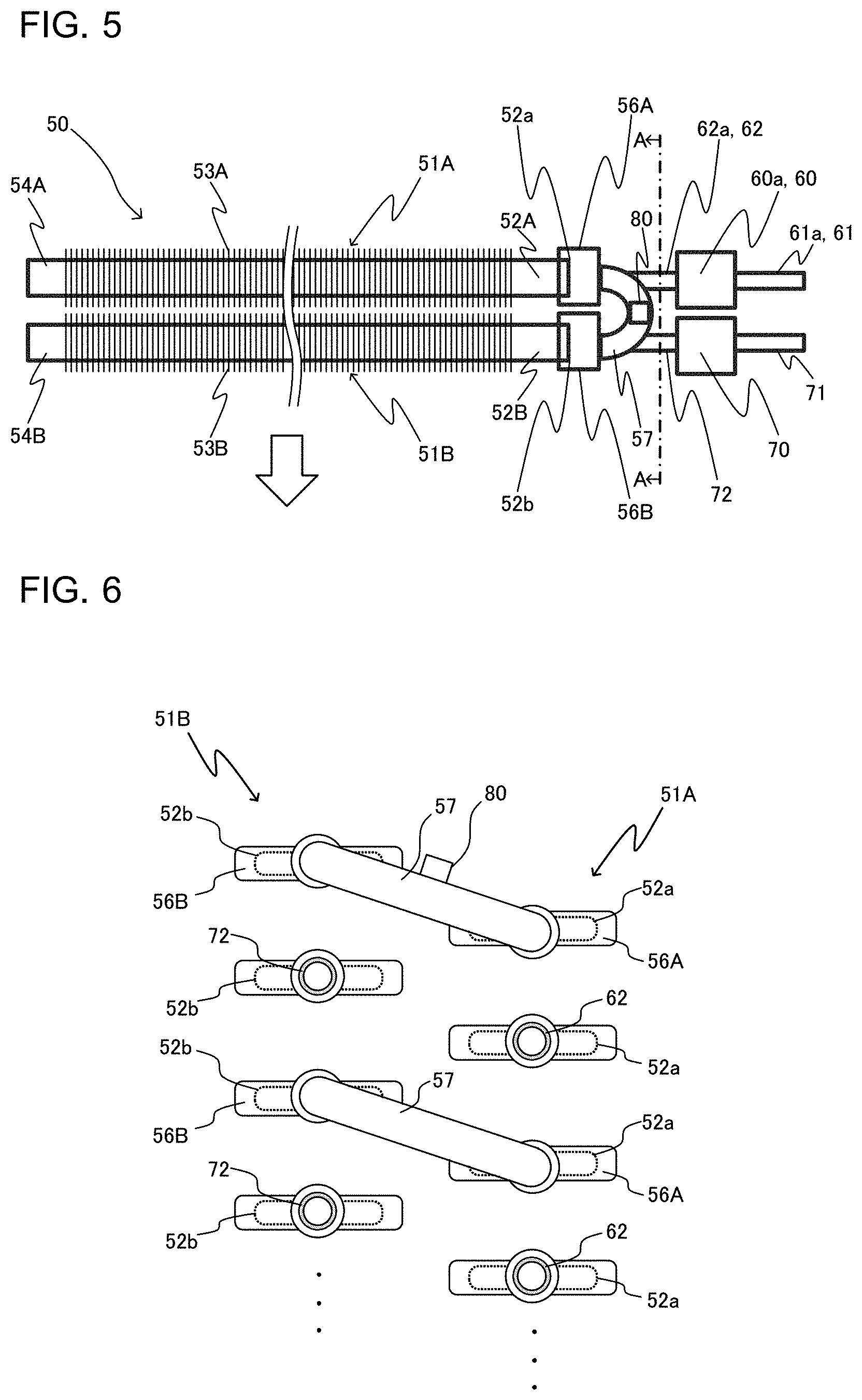
[0060] The refrigeration cycle apparatus 100 is capable of performing the cooling operation or the heating operation in the load-side unit 100B based on an instruction from the load-side unit 100B.
[0061] The respective operations of the actuators are controlled by the controller 40 that receives input of information transmitted from various sensors (the temperature sensors including the temperature sensor 80 and the pressure sensors) and a remote controller.
[Heating Operation]
[0062] The heating operation performed by the refrigeration cycle apparatus 100 will first be described. The flow of the refrigerant during the heating operation performed by the refrigeration cycle apparatus 100 is illustrated in FIG. 1.
[0063] When the refrigeration cycle apparatus 100 performs the heating operation, the flow switching device 11 is switched in the heat source-side unit 100A to allow the refrigerant discharged from the compressor 10 to flow into the heat exchanger 50 via the load-side heat exchanger 13. Specifically, in a heating operation mode, the refrigerant sequentially flows through the compressor 10, the flow switching device 11, the load-side heat exchanger 13, the expansion device 12, and the heat exchanger 50.
[0064] Low-temperature, low-pressure refrigerant is compressed by the compressor 10, and is discharged from the compressor 10 as high-temperature, high-pressure gas refrigerant. The high-temperature, high-pressure gas refrigerant discharged from the compressor 10 flows into the load-side heat exchanger 13 via the flow switching device 11. The refrigerant flowing into the load-side heat exchanger 13 exchanges heat (is condensed) with air supplied by the load-side fan 13A attached to the load-side heat exchanger 13, and flows from the load-side heat exchanger 13 as high-temperature, high-pressure liquid refrigerant. With the heat transferred from the refrigerant to the air in the load-side heat exchanger 13, the air is heated. The heated air is supplied to the air-conditioned space to thereby heat the air-conditioned space.
[0065] The high-temperature, high-pressure liquid refrigerant flowing from the load-side heat exchanger 13 is converted into low-temperature, low-pressure liquid refrigerant (or two-phase refrigerant) by the expansion device 12. The refrigerant flows into the heat exchanger 50. The refrigerant flowing into the heat exchanger 50 exchanges heat (is evaporated) with air supplied by the heat source-side fan 50A attached to the heat exchanger 50, and flows from the heat exchanger 50 as low-temperature, low-pressure gas refrigerant. The refrigerant flowing from the heat exchanger 50 is again suctioned into the compressor 10 via the flow switching device 11. During the continuation of the heating operation, the cycle from the discharge of the refrigerant from the compressor 10 to the suction of the refrigerant into the compressor 10 is repeated.
[Cooling Operation]
[0066] The cooling operation performed by the refrigeration cycle apparatus 100 will now be described. The flow of the refrigerant during the cooling operation performed by the refrigeration cycle apparatus 100 is illustrated in FIG. 2.
[0067] When the refrigeration cycle apparatus 100 performs the cooling operation, the flow switching device 11 is switched in the heat source-side unit 100A to allow the refrigerant discharged from the compressor 10 to flow into the load-side heat exchanger 13 via the heat exchanger 50. Specifically, in the cooling operation, the refrigerant sequentially flows through the compressor 10, the flow switching device 11, the heat exchanger 50, the expansion device 12, and the load-side heat exchanger 13.
[0068] Low-temperature, low-pressure refrigerant is compressed by the compressor 10, and is discharged from the compressor 10 as high-temperature, high-pressure gas refrigerant. The high-temperature, high-pressure gas refrigerant discharged from the compressor 10 flows into the heat exchanger 50 via the flow switching device 11. The refrigerant flowing into the heat exchanger 50 exchanges heat (is condensed) with air supplied by the heat source-side fan 50A attached to the heat exchanger 50, and flows from the heat exchanger 50 as low-temperature, high-pressure liquid refrigerant.
[0069] The low-temperature, high-pressure liquid refrigerant flowing from the heat exchanger 50 is converted into low-temperature, low-pressure liquid refrigerant (or two-phase refrigerant) by the expansion device 12, and flows into the load-side heat exchanger 13. The refrigerant flowing into the load-side heat exchanger 13 exchanges heat (is evaporated) with air supplied by the load-side fan 13A attached to the load-side heat exchanger 13, and flows from the load-side heat exchanger 13 as low-temperature, low-pressure gas refrigerant. With the refrigerant receiving heat from the air in the load-side heat exchanger 13, the air is cooled. The cooled air is supplied to the air-conditioned space to thereby cool the air-conditioned space. The refrigerant flowing from the load-side heat exchanger 13 is again suctioned into the compressor 10 via the flow switching device 11. During the continuation of the cooling operation, the cycle from the discharge of the refrigerant from the compressor 10 to the suction of the refrigerant into the compressor 10 is repeated.
<Details of Heat Source-Side Unit 100A>
[0070] Details of the heat source-side unit 100A according to Embodiment of the present invention will now be described.
[0071] FIG. 3 is a perspective view schematically illustrating an example of the heat exchanger 50 installed in the heat source-side unit 100A. FIG. 4 is a perspective view schematically illustrating another example of the heat exchanger 50 installed in the heat source-side unit 100A. The heat source-side unit 100A will be described in detail with reference to FIGS. 3 and 4 in addition to FIGS. 1 and 2.
[0072] As described above, the heat source-side unit 100A is equipped with the heat exchanger 50, which functions as a heat source-side heat exchanger.
[0073] The heat source-side unit 100A is further equipped with the temperature sensor 80 that measures the temperature of the refrigerant flowing through the heat exchanger 50. Temperature information obtained through the measurement with the temperature sensor 80 is transmitted to the controller 40 to be used in controlling the actuators.
[0074] The heat exchanger 50 includes a first heat exchanging unit 51A disposed on the upwind side in a passing direction of air passing through the heat exchanger 50 (a void arrow in the drawing), a second heat exchanging unit 51B disposed on the downwind side in the passing direction of the air, a first header 60 connected to the first heat exchanging unit 51A, and a second header 70 connected to the second heat exchanging unit 51B.
[0075] In the following description, the first heat exchanging unit 51A and the second heat exchanging unit 51B may be collectively referred to as the heat exchanging units. Further, the first header 60 and the second header 70 may be collectively referred to as the header units.
[0076] The first heat exchanging unit 51A and the second heat exchanging unit 51B are arranged side by side along the passing direction of the air passing through the heat exchanger 50 (the void arrow in the drawing).
[0077] Similarly to the first heat exchanging unit 51A and the second heat exchanging unit 51B, the first header 60 and the second header 70 are arranged side by side along the passing direction of the air passing through the heat exchanger 50 (the void arrow in the drawing).
[0078] Embodiment illustrates an example in which the heat exchanger 50 is configured to have two columns: the first heat exchanging unit 51A and the second heat exchanging unit 51B. The heat exchanger 50, however, may be configured to have three or more columns. In this case, the heat exchanger 50 may additionally include a heat exchanging unit having a configuration equivalent to the configuration of the first heat exchanging unit 51A or the second heat exchanging unit 51B.
[First Heat Exchanging Unit 51A]
[0079] The first heat exchanging unit 51A includes a plurality of heat transfer tubes 52A and a plurality of fins 53A joined to the plurality of heat transfer tubes 52A by a method such as brazing, for example.
[0080] The heat transfer tubes 52A are flat tubes, for example, and a plurality of passages are formed inside each of the heat transfer tubes 52A.
[0081] The heat transfer tubes 52A are arranged in a plurality of rows in a direction crossing the passing direction of the passing air (the void arrow in the drawing). One end portion and an other end portion of each of the plurality of heat transfer tubes 52A are arranged side by side near the first header 60 to face the first header 60.
[0082] Further, the one end portion and the other end portion of each of the plurality of heat transfer tubes 52A are connected by a hairpin part 54A bent into a hairpin shape.
[Second Heat Exchanging Unit 51B]
[0083] The second heat exchanging unit 51B includes a plurality of heat transfer tubes 52B and a plurality of fins 53B joined to the plurality of heat transfer tubes 52B by a method such as brazing, for example.
[0084] The heat transfer tubes 52B are flat tubes, for example, and a plurality of passages are formed inside each of the heat transfer tubes 52B.
[0085] The heat transfer tubes 52B are arranged in a plurality of rows in a direction crossing the passing direction of the passing air (the void arrow in the drawing). One end portion and an other end portion of each of the plurality of heat transfer tubes 52B are arranged side by side near the second header 70 to face the second header 70.
[0086] Further, the one end portion and the other end portion of each of the plurality of heat transfer tubes 52B are connected by a hairpin part 54B bent into a hairpin shape.
[0087] The heat transfer tubes 52A and 52B are not limited to the flat tubes, and may be cylindrical pipes. Further, in the illustrated example, each of the heat transfer tubes 52A includes the hairpin part 54A bent into a U-shape, and each of the heat transfer tubes 52B includes the hairpin part 54B bent into a U-shape. In place of the hairpin part 54A or 54B, however, a pipe such as a U-shaped pipe having passages formed therein may be used as a part separated from the heat transfer tube 52A or 52B to form bent passages.
[First Header 60]
[0088] The first header 60 functions as a liquid header, and is formed by two or more branching units arranged in the vertical direction. In FIG. 3, a branching unit of the two or more branching units disposed on the upper side in the vertical direction is illustrated as an upper branching unit 60a, and a branching unit of the two or more branching units disposed on the lower side in the vertical direction is illustrated as a lower branching unit 60b. The upper branching unit 60a is connected to some of the heat transfer tubes 52A allocated thereto, and the lower branching unit 60b is connected to some of the heat transfer tubes 52A allocated thereto.
[0089] Herein, the vertical direction means the vertical direction of the heat exchanger 50 as installed in the heat source-side unit 100A.
[0090] With the first header 60 formed by the plurality of branching units, the head difference between paths due to the pressure loss in the heat transfer tubes 52A is mitigated, and the difference in the flow rate of the refrigerant between the paths is reduced. The reason therefor will be described in detail later.
[0091] As illustrated in FIG. 4, the upper branching unit 60a is connected to a refrigerant pipe 15a via a connecting pipe 61a.
[0092] Further, the lower branching unit 60b is connected to a refrigerant pipe 15b via a connecting pipe 61b.
[0093] Further, the refrigerant pipes 15a and 15b are connected to the corresponding refrigerant pipe 15 via a distributor 85.
[0094] The connecting pipes 61a and 61b are cylindrical pipes, for example.
[0095] Inside the upper branching unit 60a, at least one distributing and combining passage 65a is formed. When the heat exchanger 50 operates as an evaporator, the distributing and combining passage 65a serves as a distributing passage that allows the refrigerant flowing from the refrigerant pipe 15a to flow into the corresponding plurality of heat transfer tubes 52A of the first heat exchanging unit 51A to be distributed thereto. Further, when the heat exchanger 50 operates as a condenser (radiator), the distributing and combining passage 65a serves as a combining passage that allows flows of refrigerant flowing from the corresponding plurality of heat transfer tubes 52A of the first heat exchanging unit 51A to combine together and flow into the refrigerant pipe 15a. That is, one side of the distributing and combining passage 65a is connected to the corresponding plurality of heat transfer tubes 52A, and the other side of the distributing and combining passage 65a is connected to the refrigerant pipe 15a.
[0096] Inside the lower branching unit 60b, at least one distributing and combining passage 65b is formed. When the heat exchanger 50 operates as an evaporator, the distributing and combining passage 65b serves as a distributing passage that allows the refrigerant flowing from the refrigerant pipe 15b to flow into the corresponding plurality of heat transfer tubes 52A of the first heat exchanging unit 51A to be distributed thereto. Further, when the heat exchanger 50 operates as a condenser (radiator), the distributing and combining passage 65b serves as a combining passage that allows flows of refrigerant flowing from the corresponding plurality of heat transfer tubes 52A of the first heat exchanging unit 51A to combine together and flow into the refrigerant pipe 15b. That is, one side of the distributing and combining passage 65b is connected to the corresponding plurality of heat transfer tubes 52A, and the other side of the distributing and combining passage 65b is connected to the refrigerant pipe 15b.
[Second Header 70]
[0097] The second header 70 functions as a gas header. FIGS. 3 and 4 illustrate, as an example, the heat exchanger 50 including one second header 70 for the first header 60 formed by a plurality of branching units. The second header 70 may also be formed by a plurality of branching units similarly to the first header 60.
[0098] As illustrated in FIG. 4, the second header 70 is connected to the corresponding refrigerant pipe 15 via a connecting pipe 71. The connecting pipe 71 is a cylindrical pipe, for example.
[0099] Inside the second header 70, a distributing and combining passage 75 is formed. When the heat exchanger 50 operates as a condenser (radiator), the distributing and combining passage 75 serves as a distributing passage that allows the refrigerant flowing from the refrigerant pipe 15 to flow into the plurality of heat transfer tubes 52B of the second heat exchanging unit 51B to be distributed thereto. Further, when the heat exchanger 50 operates as an evaporator, the distributing and combining passage 75 serves as a combining passage that allows flows of refrigerant flowing from the plurality of heat transfer tubes 52B of the second heat exchanging unit 51B to combine together and flow into the refrigerant pipe 15. That is, one side of the distributing and combining passage 75 is connected to the plurality of heat transfer tubes 52B, and the other side of the distributing and combining passage 75 is connected to the refrigerant pipe 15.
[0100] As described above, when operating as an evaporator, the heat exchanger 50 separately includes the first header 60 and the second header 70, in which the distributing passages (the distributing and combining passages 65a and 65b) and the combining passage (the distributing and combining passage 75) are respectively formed.
[0101] In other words, when operating as a condenser, the heat exchanger 50 separately includes the second header 70 and the first header 60, in which the distributing passage (the distributing and combining passage 75) and the combining passages (the distributing and combining passages 65a and 65b) are respectively formed.
[0102] The heat transfer tubes 52A and 52B are made of aluminum, for example.
[0103] Further, the fins 53A and 53B are made of aluminum, for example. The heat transfer tubes 52A and the fins 53A are joined together by brazing, for example. The heat transfer tubes 52B and the fins 53B are joined together by brazing, for example.
[0104] Further, the number of the heat transfer tubes 52A and the number of the heat transfer tubes 52B are not limited to the respective numbers thereof illustrated in FIGS. 3 and 4.
[0105] Similarly, the number of the fins 53A and the number of the fins 53B are not limited to the respective numbers thereof illustrated in FIGS. 3 and 4.
<Connection Between Heat Exchanging Units and Header Units>
[0106] Connection between the heat exchanging units and the header units of the heat exchanger 50 will be described.
[0107] FIG. 5 is a top view schematically illustrating an example of the heat exchanger 50 installed in the heat source-side unit 100A. FIG. 6 is a schematic sectional view taken along line A-A in FIG. 5. The connection between the heat exchanging units and the header units will be described based on FIGS. 5 and 6. In FIG. 5, a void arrow represents an airflow.
[0108] As illustrated in FIGS. 5 and 6, joint parts 56A are joined to end portions 52a of the heat transfer tubes 52A near the first header 60. A passage is formed inside each of the joint parts 56A. One end portion of the passage has a shape following the outer circumferential surface of the corresponding heat transfer tube 52A, and an other end portion of the passage has a circular shape.
[0109] Further, joint parts 56B are similarly joined to end portions 52b of the heat transfer tubes 52B near the second header 70. A passage is formed inside each of the joint parts 56B. One end portion of the passage has a shape following the outer circumferential surface of the corresponding heat transfer tube 52B, and an other end portion of the passage has a circular shape.
[0110] Some of the joint parts 56A and some of the joint parts 56B are connected by inter-column connecting parts 57. Each of the inter-column connecting parts 57 is a cylindrical pipe bent into an arc shape, for example.
[0111] Some of the joint parts 56A joined to the end portions 52a of the heat transfer tubes 52A are connected to connecting pipes 62 of the first header 60. FIG. 5 illustrates the upper branching unit 60a forming the first header 60. The connecting pipes 62 connected to the upper branching unit 60a will be described as the connecting pipes 62a.
[0112] Some of the joint parts 56B joined to the end portions 52b of the heat transfer tubes 52B are connected to connecting pipes 72 of the second header 70.
[0113] Each of the connecting pipes 62 and the corresponding joint part 56A may be integrated together. Further, each of the connecting pipes 72 and the corresponding joint part 56B may be integrated together. Further, each of the inter-column connecting parts 57 and the corresponding joint parts 56A and 56B may be integrated together.
[0114] Further, FIG. 6 illustrates, as an example, the inter-column connecting parts 57 connected to the joint parts 56A and 56B in a tilted position. The inter-column connecting parts 57, however, may be horizontally connected to the joint parts 56A and 56B.
<Flow of Refrigerant in Heat Exchanger 50>
[0115] FIG. 7 is a schematic diagram illustrating a flow of refrigerant in the heat exchanger 50 installed in the heat source-side unit 100A. FIG. 8 is a graph schematically illustrating the transition of the state of the refrigerant in the heat exchanger 50 installed in the heat source-side unit 100A. A flow of refrigerant in the heat exchanger 50 will be described based on FIGS. 7 and 8. In FIG. 7, a flow of refrigerant during the operation of the heat exchanger 50 as a condenser is represented by arrows (1) to (5). Further, (1) to (5) illustrated in FIG. 8 correspond to (1) to (5) in FIG. 7. Further, in FIG. 8, temperatures of air in the heat exchanger 50 are represented by broken lines.
[0116] The refrigerant flowing through the refrigerant pipe 15 flows into the second header 70 to be divided into a plurality of flows in the distributing and combining passage 75, and flows into each of the plurality of heat transfer tubes 52B of the second heat exchanging unit 51B from the end portion 52b of the heat transfer tube 52B (arrow (1)). In this process, the refrigerant is in the gas state similar to the state of the refrigerant discharged from the compressor 10 ((1) in FIG. 8). The refrigerant flowing from the end portion 52b flows toward the other end portion of the heat transfer tube 52B. In this process, the refrigerant exchanges heat with the air supplied by the heat source-side fan 50A. In this process, the refrigerant is in the superheated gas state ((2) in FIG. 8).
[0117] The refrigerant flowing to the other end portion of the heat transfer tube 52B flows into another heat transfer tube 52B located thereabove via the hairpin part 54B (arrow (2)). The refrigerant flowing from the other end portion of the heat transfer tube 52B flows toward the end portion 52b of the heat transfer tube 52B. In this process, too, the refrigerant exchanges heat with the air supplied by the heat source-side fan 50A.
[0118] The refrigerant flowing to the end portion 52b of the heat transfer tube 52B moves to the first heat exchanging unit 51A via the inter-column connecting part 57 (arrow (3)). In this process, the refrigerant is in the two-phase gas-liquid state ((3) in FIG. 8). The refrigerant moving to the first heat exchanging unit 51A flows into the corresponding one of the plurality of heat transfer tubes 52A of the first heat exchanging unit 51A from the end portion 52a of the heat transfer tube 52A. The refrigerant flowing from the end portion 52a flows toward the other end portion of the heat transfer tube 52A. In this process, the refrigerant exchanges heat with the air supplied by the heat source-side fan 50A.
[0119] The refrigerant flowing to the other end portion of the heat transfer tube 52A flows into another heat transfer tube 52A located therebelow via the hairpin part 54A (arrow (4)). The refrigerant flowing from the other end portion flows toward the end portion 52a of the heat transfer tube 52A. In this process, too, the refrigerant exchanges heat with the air supplied by the heat source-side fan 50A. In this process, the refrigerant is in the subcooled state ((2) in FIG. 8). The refrigerant flowing to the end portion 52a of the heat transfer tube 52A flows into the first header 60 (arrow (5)). The flows of refrigerant flowing into the first header 60 combine together in the first header 60 and flow from the heat exchanger 50.
[0120] When the heat exchanger 50 operates as an evaporator, the refrigerant flows from the first header 60 to the second header 70.
[0121] Further, as to the installation position of the temperature sensor 80, which will be described later, the temperature sensor 80 may be installed at a position at which the temperature sensor 80 is capable of measuring the temperature of the refrigerant flowing through one of the positions represented by arrow (3) in FIG. 7. That is, the temperature sensor 80 may be installed on the inter-column connecting part 57 connected to the joint parts 56A and 56B at a position higher than an intermediate position in the height direction of the heat exchanger 50. Preferably, the temperature sensor 80 may be installed at the upper one of the positions illustrated in of FIG. 7.
<Installation Position of Temperature Sensor 80>
[0122] In general, a refrigeration cycle apparatus has a temperature sensor and a pressure sensor disposed at respective predetermined locations in a refrigerant circuit to measure the temperature and pressure, respectively, of the refrigerant circulating through the refrigerant circuit, to thereby protect the system of the refrigeration cycle apparatus. That is, the actuators are controlled based on temperature information and pressure information obtained through the measurements with the sensors. To protect the system, therefore, it is important to reliably measure the state of the refrigerant. There is also a refrigeration cycle apparatus in which the pressure sensor is replaced by a temperature sensor installed at a location through which two-phase gas-liquid refrigerant flows, and the temperature of the refrigerant in the two-phase state measured by the temperature sensor is converted into the pressure of the refrigerant.
[0123] When a heat exchanger operates as a condenser, the state of the refrigerant flowing through the heat exchanger transitions between the superheated gas state, the two-phase state, and the subcooled state. Therefore, it is substantially important for the system to reliably measure the temperature of the refrigerant in the two-phase state. Accordingly, the temperature sensor needs to be installed at a position at which the temperature sensor is capable of reliably measuring the refrigerant in the two-phase state.
[0124] In the heat source-side unit 100A, therefore, the temperature sensor 80 is installed at a position at which the degree of subcooling is unlikely to be obtained. Specifically, as illustrated in FIG. 5, the temperature sensor 80 is installed on an upper portion of the inter-column connecting part 57 located uppermost. With the temperature sensor 80 installed at this position, the measurement of the temperature of the refrigerant in the two-phase state in the heat exchanger 50 is improved in reliability.
[0125] The position in the heat exchanger 50 at which the degree of subcooling is unlikely to be obtained corresponds to a position on the upper branching unit 60a. The position of separation between the upper branching unit 60a and the lower branching unit 60b corresponds to the intermediate position in the vertical direction of the heat exchanger 50. That is, the temperature sensor 80 may be installed on the inter-column connecting part 57 connected to the joint parts 56A and 56B at a position higher than the intermediate position in the height direction of the heat exchanger 50. As illustrated in FIG. 5, however, it is preferable to install the temperature sensor 80 on an upper portion of the inter-column connecting part 57 located uppermost. The temperature sensor 80 may be installed not to an upper portion of the inter-column connecting part 57 but on a lower or lateral portion of the inter-column connecting part 57.
[Details of First Header 60]
[0126] A specific configuration example of the first header 60 will first be described. FIG. 9 is a longitudinal sectional view illustrating an example of the upper branching unit 60a forming the first header 60 of the heat exchanger 50 installed in the heat source-side unit 100A. FIG. 10 is a perspective view illustrating another example of the upper branching unit 60a forming the first header 60 of the heat exchanger 50 installed in the heat source-side unit 100A. For convenience of illustration, FIG. 9 illustrates a plate-shaped body as having a substantially uniform thickness. Further, FIG. 9 illustrates a section cut along a flow direction of fluid. Further, although FIG. 9 illustrates the upper branching unit 60a, the lower branching unit 60b is similar in configuration to the upper branching unit 60a.
[0127] As illustrated in FIG. 9, the first header 60 may be formed as a stacking-type header including a plate-shaped body 90. The plate-shaped body 90 is formed by alternately stacking first plate-shaped parts 91a to 91d, which serve as bare materials, and second plate-shaped parts 92a to 92d, which serve as clad materials. The first plate-shaped parts 91a and 91e are stacked as the outermost sides in a stacking direction of the plate-shaped body 90.
[0128] In the following, the first plate-shaped parts 91a to 91e may be collectively referred to as the first plate-shaped parts 91. Similarly, the second plate-shaped parts 92a to 92d may be collectively described as the second plate-shaped parts 92.
[0129] The first plate-shaped parts 91 are made of aluminum, for example. No brazing material is applied to the first plate-shaped parts 91. Each of the first plate-shaped parts 91 is formed with a through-hole forming the distributing and combining passage 65. The through-hole passes through the front surface and the back surface of the first plate-shaped part 91. With the first plate-shaped parts 91 and the second plate-shaped parts 92 stacked upon each other, the through-holes formed in the first plate-shaped parts 91 function as parts of the distributing and combining passage 65.
[0130] The second plate-shaped parts 92 are made of aluminum, for example, and are formed to be thinner than the first plate-shaped parts 91. A brazing material is applied to at least the front surface and the back surface of each of the second plate-shaped parts 92. Each of the second plate-shaped parts 92 is formed with a through-hole forming the distributing and combining passage 65. The through-hole passes through the front surface and the back surface of the second plate-shaped part 92. With the first plate-shaped parts 91 and the second plate-shaped parts 92 stacked upon each other, the through-holes formed in the second plate-shaped parts 92 function as parts of the distributing and combining passage 65.
[0131] The through-hole formed in the first plate-shaped part 91a is connected to the connecting pipe 61a. For example, a component such as a mouthpiece may be attached to a surface of the first plate-shaped part 91a from which the refrigerant flows into the first plate-shaped part 91a, and the connecting pipe 61a may be connected to the through-hole via the component such as a mouthpiece. Further, the inner circumferential surface of the through-hole formed in the first plate-shaped part 91a may have a shape that fits around the outer circumferential surface of the connecting pipe 61a, and the connecting pipe 61a may be directly connected to the through-hole without a component such as a mouthpiece.
[0132] Each of the through-holes formed in the first plate-shaped part 91e is connected to the connecting pipe 62a. For example, a component such as a mouthpiece may be attached to a surface of the first plate-shaped part 91e from which the refrigerant flows out the first plate-shaped part 91e, and the connecting pipe 62a may be connected to the through-hole via the component such as a mouthpiece. Further, the inner circumferential surface of the through-hole formed in the first plate-shaped part 91e may have a shape that fits around the outer circumferential surface of the connecting pipe 62a, and the connecting pipe 62a may be directly connected to the through-hole without a component such as a mouthpiece. The connecting pipe 62a may be inserted into the through-hole in the first plate-shaped part 91e to reach the through-hole in the first plate-shaped part 91d, to thereby connect the connecting pipe 62a to the through-hole in the first plate-shaped part 91e.
[0133] Each of the through-holes formed in the first plate-shaped parts 91a and 91c passes therethrough such that a passage section has a Z-shape, for example.
[0134] The passage section is a section of a passage cut along a direction perpendicular to the flow of fluid.
[0135] With the first plate-shaped parts 91 and the second plate-shaped parts 92 stacked upon each other, the through-holes formed in the first plate-shaped parts 91 and the through-holes formed in the second plate-shaped parts 92 communicate with each other to form the distributing and combining passage 65. That is, with the first plate-shaped parts 91 and the second plate-shaped parts 92 stacked upon each other, adjacent through-holes communicate with each other, and each of portions other than the communicating through-holes is closed by the first plate-shaped part 91 or the second plate-shaped part 92 adjacent to the portion, thereby forming the distributing and combining passage 65.
[0136] FIG. 9 illustrates an example in which the distributing and combining passage 65 has four fluid outlets for one fluid inlet. However, the number of branches is not limited to four.
[0137] A description will be given of a flow of refrigerant in the upper branching unit 60a when the refrigerant flows into the upper branching unit 60a from the connecting pipe 61a.
[0138] As illustrated in FIG. 9, the refrigerant flowing through the connecting pipe 61a flows into the upper branching unit 60a from the through-hole in the first plate-shaped part 91a as a fluid input. The refrigerant flows into the through-hole in the second plate-shaped part 92a.
[0139] The refrigerant flowing into the through-hole in the second plate-shaped part 92a flows into the center of the through-hole in the first plate-shaped part 91b. The refrigerant flowing into the center of the through-hole in the first plate-shaped part 91b hits against a surface of the second plate-shaped part 92b stacked adjacent to the first plate-shaped part 91b, and branches into flows each flowing to an end portion of the through-hole in the first plate-shaped part 91b. Each of the flows of refrigerant reaching the end portion of the through-hole in the first plate-shaped part 91b passes through the corresponding through-hole in the second plate-shaped part 92b, and flows into the center of the corresponding through-hole in the first plate-shaped part 91c.
[0140] The refrigerant flowing into the center of the through-hole in the first plate-shaped part 91c hits against a surface of the second plate-shaped part 92c stacked adjacent to the first plate-shaped part 91c, and branches into flows each flowing to an end portion of the through-hole in the first plate-shaped part 91c. Each of the flows of refrigerant reaching the end portion of the through-hole in the first plate-shaped part 91c passes through the corresponding through-hole in the second plate-shaped part 92c, and flows into the corresponding through-hole in the first plate-shaped part 91d. The refrigerant flowing into the through-hole in the first plate-shaped part 91d passes through the corresponding through-hole in the second plate-shaped part 92d, and flows into the corresponding heat transfer tube 52A via the connecting pipe 62 located in the through-hole in the first plate-shaped part 91e.
[0141] With the first header 60 formed as a stacking-type header, the uniformity in distribution of the refrigerant in the first header 60 is improved.
[0142] Although FIG. 9 illustrates an example in which the first header 60 is formed as a stacking-type header, the first header 60 may be formed as a cylindrical header, as illustrated in FIG. 10.
[0143] A configuration example of the branching units forming the first header 60 will now be described. FIG. 11 is a perspective view illustrating a configuration example of the first header 60 of the heat exchanger 50 installed in the heat source-side unit 100A. FIG. 12 is a perspective view illustrating another configuration example of the first header 60 of the heat exchanger 50 installed in the heat source-side unit 100A.
[0144] As illustrated in FIG. 11, the first header 60 may be configured with the upper branching unit 60a and the lower branching unit 60b separated from each other. In this case, the first header 60 may be configured with each of the upper branching unit 60a and the lower branching unit 60b formed as a stacking-type header or a cylindrical header. Further, the first header 60 may be configured with one of the upper branching unit 60a and the lower branching unit 60b formed as a stacking-type header and the other one of the upper branching unit 60a and the lower branching unit 60b formed as a cylindrical header.
[0145] Further, as illustrated in FIG. 12, the entire first header 60 may be integrally formed with a divider 69 placed therein to form the upper branching unit 60a and the lower branching unit 60b. As illustrated in FIG. 12, the first header 60 may include a plurality of dividers 69 to form an intermediate branching unit 60c. If the first header 60 is formed as a stacking-type header, the plate-shaped body 90 may be formed with a plurality of fluid inlets, and the distributing and combining passages 65 from the fluid inlets to the fluid outlets may be configured not to communicate with each other. Further, if the first header 60 is formed as a cylindrical header, the internal space of the first header 60 may be divided into a plurality of spaces with the divider(s) 69, as illustrated in FIG. 12.
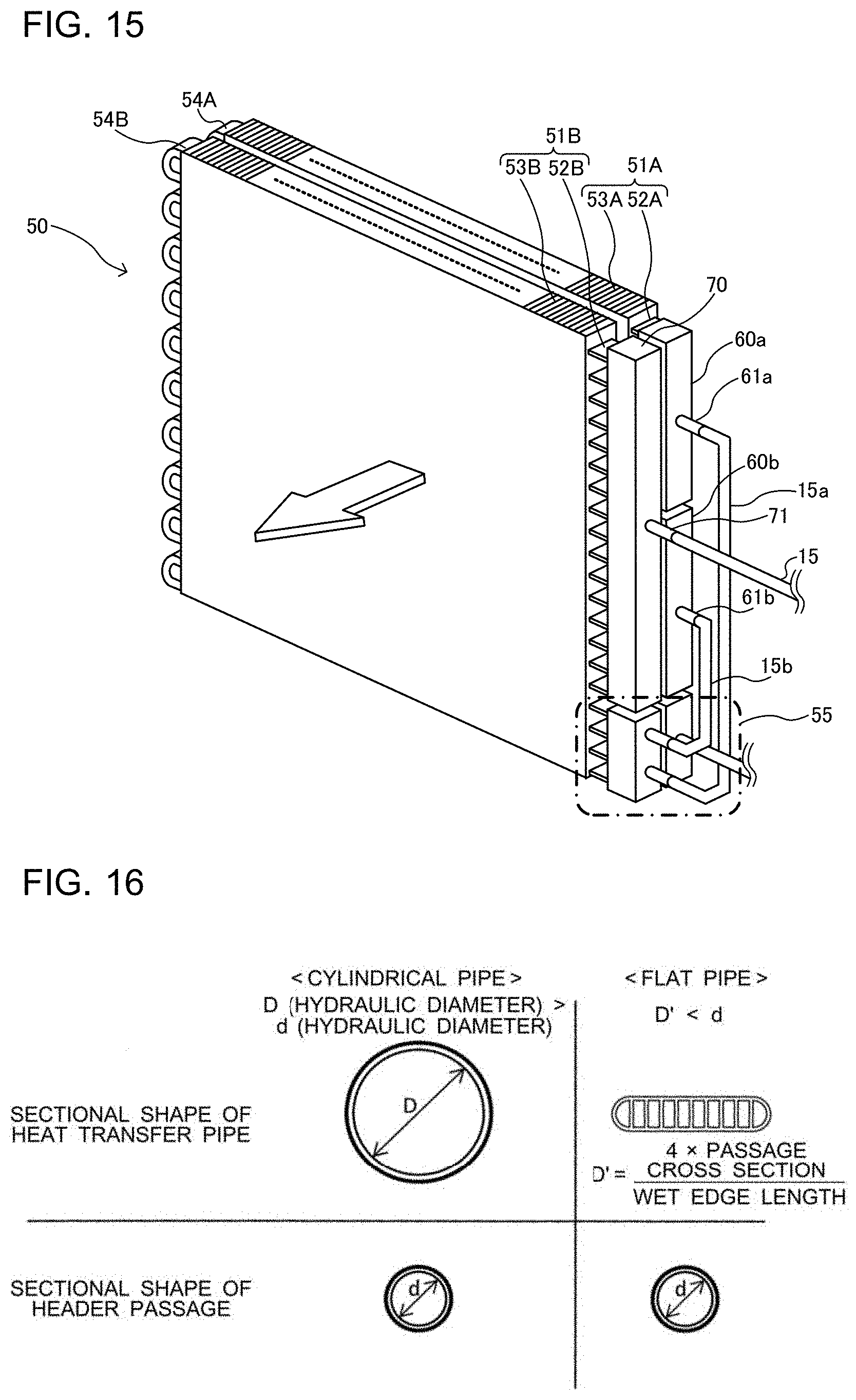
[0146] A description will now be given of an operation of the first header 60 including the plurality of branching units. FIG. 13 is a graph for illustrating the pressure loss in a header not including a plurality of branching units. FIG. 14 is a graph for illustrating the pressure loss in a header including a plurality of branching units. FIG. 15 is a perspective view schematically illustrating still another example of the heat exchanger 50 installed in the heat source-side unit 100A. FIG. 16 is a table for illustrating combinations of heat transfer tubes and header passages. An operation of a header including a plurality of branching units will be described based on FIGS. 13 to 16.
[0147] In FIGS. 13 and 14, the vertical axis represents the pressure, and the horizontal axis represents the temperature. Further, in FIGS. 13 and 14, "A", "B," "C," and "D" represent a subcooling line inlet, a header inlet, a heat transfer tube inlet, and a heat transfer tube outlet, respectively. Further, in FIG. 16, the upper row illustrates the sectional shapes of heat transfer tubes, and the lower row illustrates the sectional shapes of header passages. Further, in FIG. 16, the left side illustrates a combination of a cylindrical pipe and a header passage, and the right side illustrates a combination of a flat tube and a header passage.
[0148] When a heat exchanger is operated as a condenser, refrigerant branched in a header exchanges heat with air and is liquefied, and a liquid head for the liquefied refrigerant causes variation in the pressure loss between paths. Specifically, the higher a path is located, the more easily the refrigerant flows through the path, increasing the flow rate of the refrigerant. Meanwhile, the lower the path is located, the less easily the refrigerant flows through the path. As illustrated in FIG. 15, therefore, an ordinary heat exchanger operating as a condenser subcools the refrigerant on the downstream side of the heat transfer tubes in many cases to improve the heat exchange performance. Downstream-side heat transfer tubes for subcooling the refrigerant are referred to as a subcooling line (a subcooling line 55 illustrated in FIG. 15).
[0149] A case will be examined in which the subcooling line illustrated in FIG. 15 uses heat transfer tubes (flat tubes) each having an elliptical sectional shape illustrated on the right side of FIG. 16.
[0150] The relational expression of the pressure loss in the flat tube illustrated on the right side of FIG. 16 is .DELTA.P.varies.u{circumflex over ( )}2.times.L/d.
[0151] Herein, u is "Gr/A," wherein A is ".pi.d{circumflex over ( )}2/4." Further, .DELTA.P represents the "pressure loss," u represents the "flow velocity," L represents the "pipe length," and d represents the "hydraulic diameter."
[0152] As illustrated on the left side of FIG. 16, in a heat exchanger employing a combination of heat transfer tubes each having a circular sectional shape and header passages each having a circular sectional shape, narrow tubes such as capillaries are used as pipes connecting the header passages and the heat transfer tubes. Therefore, the hydraulic diameter of each of the heat transfer tubes is greater than the hydraulic diameter of each of distributor passages. Consequently, the heat exchanger is unlikely to be affected by the liquid head, reducing the difference in flow rate between an upper path and a lower path during cooling.
[0153] Meanwhile, as illustrated on the right side of FIG. 16, in a heat exchanger employing a combination of flat tubes and header passages each having a circular sectional shape, the header passages and the flat tubes are connected with joint parts. A flat tube usually has a small hydraulic diameter, such as 1 mm or less. Therefore, the hydraulic diameter of each of the heat transfer tubes is smaller than the hydraulic diameter of each of the distributor passages. Consequently, the pressure loss in the header passages is reduced, and the heat exchanger is likely to be affected by the liquid head. That is, the heat exchanger 50 may also employ the configuration connecting the header passages and the flat tubes with the joint parts 56A, and thus is required to address the pressure loss in the header passages.
[0154] The relationship between the flow rate of the refrigerant and the degree of subcooling will be described.
[0155] It is assumed here that a relationship Gr1>Gr2 holds in which Gr1 represents the flow rate of the refrigerant in one of a plurality of paths in a heat exchanger, and Gr2 represents the flow rate of the refrigerant in another one of the plurality of paths in the heat exchanger. When it is further assumed that an exchanged heat amount (Q) and an inlet enthalpy (Hi) are equal between the plurality of paths, an equation Q=Gr1.times.(Hi-Ho1)=Gr2.times.(Hi-Ho2) is established. Since the relationship Gr1>Gr2 holds, it is understood that an outlet enthalpy (Ho2) in the another one of the plurality of paths is lower than an outlet enthalpy (Ho1) in the one of the plurality of paths. That is, it is considered that the lower the flow rate of the refrigerant is, the more likely the degree of subcooling is to be obtained.
[0156] If a heat exchanger having a subcooling line and a header not including a plurality of branching units is operated as an evaporator, the pressure loss in the refrigerant passages inside the header is increased, as illustrated in FIG. 13 (.DELTA.P2 illustrated in FIG. 13), and the temperature of the refrigerant at the inlet of the header is higher than the temperature of air. That is, the amount of refrigerant not evaporated is increased, thereby reducing the heat exchange efficiency and causing inefficiency. For example, according to heat exchangers in the past such as the heat exchanger described in Patent Literature 1, lower heat transfer tubes are used as the subcooling line. Therefore, the paths are connected with narrow tubes, to thereby obtain a pressure loss and reduce the head difference. This configuration, however, increases the pressure loss in the refrigerant passages inside the header, not improving the heat exchange efficiency.
[0157] Meanwhile, if a heat exchanger having a subcooling line and a header including a plurality of branching units, such as the heat exchanger 50, is operated as an evaporator, the pressure loss in the refrigerant passages inside the header is reduced, as illustrated in FIG. 14 (.DELTA.P2 illustrated in FIG. 14), and the temperature of the refrigerant at the inlet of the header is lower than the temperature of air. That is, the entire heat exchanger is capable of evaporating the refrigerant, improving the heat exchange efficiency.
[0158] In the heat source-side unit 100A, therefore, the first header 60 of the heat exchanger 50 is formed by two or more branching units arranged in the vertical direction. The heat source-side unit 100A, therefore, is capable of mitigating the head difference between the paths due to the pressure loss in the heat transfer tubes 52A in the first header 60, and thus reducing the difference in the flow rate of the refrigerant between all of the heat transfer tubes. The heat source-side unit 100A is therefore capable of performing heat exchange in the entire heat exchanger 50, thereby improving the heat exchange efficiency.
[0159] Further, according to the heat source-side unit 100A, even if the distributor 85 as illustrated in FIG. 4 is used, the branching depends on the number of branching units forming the first header 60. It is therefore possible to suppress an increase in the size of the body of the distributor and an increase in the number of pipes connected to the distributor 85. Accordingly, there is no need to unnecessarily increase the internal space of the heat source-side unit 100A, allowing effective use of space.
<Effects of Heat Source-Side Unit 100A and Refrigeration Cycle Apparatus 100>
[0160] As described above, the heat source-side unit 100A includes the heat exchanger 50 that includes the plurality of heat exchanging units (the first heat exchanging unit 51A and the second heat exchanging unit 51B) and the temperature sensor 80 that measures the temperature of the refrigerant flowing through the heat exchanger 50. The heat exchanger 50 includes: the first header 60 connected to the first heat exchanging unit 51A, which is at least one of the plurality of heat exchanging units, and including the plurality of branching units arranged in the vertical direction (the upper branching unit 60a and the lower branching unit 60b); the second header 70 connected to the second heat exchanging unit 51B, which is at least one of rest of the plurality of heat exchanging units; and the plurality of inter-column connecting parts 57 that connect parts of the heat transfer tubes 52A forming the first heat exchanging unit 51A and parts of the heat transfer tubes 52B forming the second heat exchanging unit 51B. The temperature sensor 80 is installed on the inter-column connecting part 57 included in the plurality of inter-column connecting parts 57 and located higher than the intermediate position in the vertical direction of the heat exchanger 50.
[0161] According to the heat source-side unit 100A, therefore, the temperature of the two-phase gas-liquid refrigerant flowing through the inter-column connecting part 57 is measured. It is therefore possible to accurately measure the temperature of the two-phase refrigerant used in controlling the actuators included in the refrigeration cycle apparatus 100, and to perform efficient system protection.
[0162] Further, according to the heat source-side unit 100A, the temperature sensor 80 is installed on the inter-column connecting part 57 located uppermost among the plurality of inter-column connecting parts 57. It is therefore possible to measure the temperature of the refrigerant at the inter-column connecting part 57 disposed at a position at which the degree of subcooling is unlikely to be obtained. Accordingly, the temperature of the two-phase refrigerant is further reliably measured.
[0163] Further, in the heat source-side unit 100A, each of the heat transfer tubes 52A forming the first heat exchanging unit 51A has the hairpin part 54A on the end portion of the heat transfer tube 52A opposite to the end portion of the heat transfer tube 52A near the first header 60. Each of the heat transfer tubes 52B forming the second heat exchanging unit 51B has the hairpin part 54B on the end portion of the heat transfer tube 52B opposite to the end portion of the heat transfer tube 52B near the second header 70. The inter-column connecting parts 57 are disposed near the first header 60 and the second header 70.
[0164] According to the heat source-side unit 100A, therefore, it is possible to install the temperature sensor 80 on the inter-column connecting part 57 without employing a complicated configuration.
[0165] Further, according to the heat source-side unit 100A, the first header 60 is a stacking-type header having the plurality of plate-shaped parts (the first plate-shaped parts 91 and the second plate-shaped parts 92) stacked upon each other. Accordingly, the uniformity in distribution of the refrigerant is improved.
[0166] Further, according to the heat source-side unit 100A, the heat transfer tubes (the heat transfer tubes 52A and 52B) are flat tubes. Accordingly, the heat exchange efficiency of each of the heat exchanging units is improved.
[0167] Further, the heat source-side unit 100A includes the heat source-side fan 50A that supplies air to the heat exchanger 50, and the first heat exchanging unit 51A and the second heat exchanging unit 51B are arranged side by side in the passing direction of the air supplied by the heat source-side fan 50A. Accordingly, there is no increase in the size of the heat exchanger 50.
[0168] Further, the refrigeration cycle apparatus 100 includes the above-described heat source-side unit 100A and the load-side unit 100B connected to the heat source-side unit 100A, and thus has all of the effects of the heat source-side unit 100A. That is, according to the refrigeration cycle apparatus 100, the measurement of the temperature of the two-phase gas-liquid refrigerant is improved in reliability. Accordingly, the control of the actuators is optimized, and efficient system protection is realized.
* * * * *
D00000
D00001
D00002
D00003
D00004
D00005
D00006
D00007
D00008
XML
uspto.report is an independent third-party trademark research tool that is not affiliated, endorsed, or sponsored by the United States Patent and Trademark Office (USPTO) or any other governmental organization. The information provided by uspto.report is based on publicly available data at the time of writing and is intended for informational purposes only.
While we strive to provide accurate and up-to-date information, we do not guarantee the accuracy, completeness, reliability, or suitability of the information displayed on this site. The use of this site is at your own risk. Any reliance you place on such information is therefore strictly at your own risk.
All official trademark data, including owner information, should be verified by visiting the official USPTO website at www.uspto.gov. This site is not intended to replace professional legal advice and should not be used as a substitute for consulting with a legal professional who is knowledgeable about trademark law.