Thermomagnetic Cycle Device
KISHI; Kentaro ; et al.
U.S. patent application number 16/543705 was filed with the patent office on 2020-03-05 for thermomagnetic cycle device. The applicant listed for this patent is DENSO CORPORATION. Invention is credited to Kentaro KISHI, Yasunori NIIYAMA.
| Application Number | 20200072509 16/543705 |
| Document ID | / |
| Family ID | 69640981 |
| Filed Date | 2020-03-05 |


View All Diagrams
| United States Patent Application | 20200072509 |
| Kind Code | A1 |
| KISHI; Kentaro ; et al. | March 5, 2020 |
THERMOMAGNETIC CYCLE DEVICE
Abstract
A device comprises an element bed providing a plurality of unit channels each containing an NICE element. The heat transport device has a channel switching mechanism and a biasing mechanism. The channel switching mechanism forms an inlet valve for allowing the heat transport medium to flow into the unit channel and an outlet valve for allowing the heat transport medium to flow out of the unit channel. The biasing mechanism applies different biasing forces to the inlet valve and the outlet valve. The magnitude relationship of the biasing force is the same as the magnitude relationship between the pressure of the heat transport medium acting on the inlet valve and the pressure of the heat transport medium acting on the outlet valve.
| Inventors: | KISHI; Kentaro; (Kariya-city, JP) ; NIIYAMA; Yasunori; (Kariya-city, JP) | ||||||||||
| Applicant: |
|
||||||||||
|---|---|---|---|---|---|---|---|---|---|---|---|
| Family ID: | 69640981 | ||||||||||
| Appl. No.: | 16/543705 | ||||||||||
| Filed: | August 19, 2019 |
| Current U.S. Class: | 1/1 |
| Current CPC Class: | F25B 21/00 20130101; F25B 2321/0021 20130101 |
| International Class: | F25B 21/00 20060101 F25B021/00 |
Foreign Application Data
| Date | Code | Application Number |
|---|---|---|
| Aug 30, 2018 | JP | 2018-161888 |
Claims
1. A thermomagnetic cycle device comprising: an element bed which provides a plurality of unit channels each containing an MCE element demonstrating a magneto caloric effect; a magnetic field modulation device which modulates a magnetic field applied to the element bed; and a heat transport device for generating a reciprocating flow of a heat transport medium which exchanges heat with the MCE element the heat transport device includes: a unidirectional pump which flows the heat transport medium; a channel switching mechanism which forms, at one end and/or the other end of the unit channel, an inlet valve which allows the heat transport medium to flow into the unit channel and an outlet valve which allows the heat transport medium to flow out of the unit channel; and a biasing mechanism for applying different biasing forces to the inlet valve and the outlet valve, wherein a magnitude relationship of the biasing forces is the same as the magnitude relationship between the pressure of the heat transport medium acting on the inlet valve and the pressure of the heat transport medium acting on the outlet valve.
2. The thermomagnetic cycle device claimed in claim 1, wherein the channel switching mechanism is disposed to oppose the plurality of unit channels, includes a plurality of segments providing the inlet valve and the outlet valve, and comprises a valve element which rotates relative to the plurality of unit channels.
3. The thermomagnetic cycle device claimed in claim 2, wherein the biasing mechanism generates a pressing force that presses the element bed and the segment.
4. The thermomagnetic cycle device claimed in claim 1, wherein the channel switching mechanism includes a plurality of on-off valves each fixedly arranged in one unit channel and providing the inlet valve and the outlet valve.
5. The thermomagnetic cycle device claimed in claim 4, wherein the biasing mechanism adjusts a compression amount of a seal member of the on-off valve.
6. The thermomagnetic cycle device claimed in claim 1, wherein the biasing mechanism includes a variable element that varies the biasing force according to the pressure of the heat transport medium.
7. The thermomagnetic cycle device claimed in claim 6, wherein the variable element is a pressure sensitive element whose dimension changes in accordance with the pressure of the heat transport medium.
8. The thermomagnetic cycle device claimed in claim 1, wherein the biasing mechanism includes an invariable element that applies the biasing force independent of the pressure of the heat transport medium.
9. The thermomagnetic cycle device claimed in claim 1, wherein the biasing mechanism includes an elastic member.
10. The thermomagnetic cycle device claimed in claim 1, wherein the biasing mechanism includes an electromagnetic movable mechanism.
Description
CROSS REFERENCE TO RELATED APPLICATION
[0001] The present disclosure is based on Japanese Patent Application No. 2018461888 filed on Aug. 30, 2018, the whole contents of which are incorporated herein by reference.
FIELD
[0002] Disclosure in this specification relates to a thermomagnetic cycle device.
BACKGROUND
[0003] A thermomagnetic cycle device or a magneto-thermal cycle device utilizes the magneto-thermal properties of a magneto-caloric element. These devices include a magnetic field modulation device that periodically changes a magnetic field, and a heat transport device that creates a reciprocating flow of a heat transport medium. There is a need for further improvements in thermomagnetic cycle devices.
SUMMARY
[0004] A thermomagnetic cycle device disclosed comprises: an element bed which provides a plurality of unit channels each containing an MCE element that demonstrates a magneto caloric effect; a magnetic field modulation device which modulates a magnetic field applied to the element bed; and a heat transport device for generating a reciprocating flow of a heat transport medium which exchanges heat with the MCE element. The heat transport device includes: a unidirectional pump which flows the heat transport medium; a channel switching mechanism which forms, at one end and/or the other end of the unit channel, an inlet valve which allows the heat transport medium to flow into the unit channel and an outlet valve which allows the heat transport medium to flow out of the unit channel; and a biasing mechanism for applying different biasing forces to the inlet valve and the outlet valve, wherein a magnitude relationship of the biasing forces is the same as the magnitude relationship between the pressure of the heat transport medium acting on the inlet valve and the pressure of the heat transport medium acting on the outlet valve.
[0005] According to the disclosed thermomagnetic cycle device, different biasing forces are applied to the inlet valve and the outlet valve by the biasing mechanism. The magnitude relation of the biasing force is the same as the magnitude relation between the pressure of the heat transport medium acting on the inlet valve and the pressure of the heat transport medium acting on the outlet valve. For example, if the biasing force applied to the inlet valve is greater than the biasing force applied to the outlet valve, the pressure of the heat transport medium acting on the inlet valve is greater than the pressure of the heat transport medium acting on the outlet valve. For example, if the biasing force applied to the outlet valve is greater than the biasing force applied to the inlet valve, the pressure of the heat transport medium acting on the outlet valve is greater than the pressure of the heat transport medium acting on the inlet valve. This provides a seal that withstands the pressure of the heat transport medium at the inlet valve and the outlet valve. Furthermore, the power for exerting the biasing force at the inlet valve and the outlet valve is suppressed. As a result, mechanical loss is suppressed.
[0006] The disclosed aspects in this specification adopt different technical solutions from each other in order to achieve their respective objectives. Reference numerals in parentheses described in claims and this section exemplarily show corresponding relationships with parts of embodiments to be described later and are not intended to limit technical scopes. The objects, features, and advantages disclosed in this specification will become apparent by referring to following detailed descriptions and accompanying drawings.
BRIEF DESCRIPTION OF THE DRAWINGS
[0007] FIG. 1 is a cross-sectional view of a thermal apparatus according to a first embodiment;
[0008] FIG. 2 is a cross-sectional view taken along a line II-II of FIG. 1;
[0009] FIG. 3 is a circuit diagram showing pressure distribution of a heat transport medium;
[0010] FIG. 4 is an exploded perspective view showing a seal mechanism at a hot end;
[0011] FIG. 5 is a developed view showing the seal mechanism at the hot end;
[0012] FIG. 6 is an exploded perspective view showing the seal mechanism at a cold end;
[0013] FIG. 7 is a developed view of the seal mechanism at the cold end;
[0014] FIG. 8 is a circuit diagram showing a pressure distribution according to a second embodiment;
[0015] FIG. 9 is a developed view showing a sealing mechanism;
[0016] FIG. 10 is a development view showing a seal mechanism of a third embodiment;
[0017] FIG. 11 is a developed view showing a sealing mechanism of a fourth embodiment;
[0018] FIG. 12 is a developed view showing a seal mechanism of a h embodiment;
[0019] FIG. 13 is a cross-sectional view of a thermal apparatus according to a sixth embodiment;
[0020] FIG. 14 is a cross-sectional view taken along a line XIV-XIV of FIG. 13;
[0021] FIG. 15 is a cross-sectional view taken along a line XV-XV in FIG. 13;
[0022] FIG. 16 is a cross-sectional view showing an operating state of a high pressure valve; and
[0023] FIG. 17 is a cross-sectional view showing the operating state of the low pressure valve.
EMBODIMENT
[0024] Hereinafter, a plurality of embodiments will be described with reference to the drawings. In some embodiments, parts that are functionally and/or structurally corresponding and/or associated are given the same reference numerals, or reference numerals with different hundred digit or more digits. For corresponding parts and/or associated parts, reference can be made to the description of other embodiments.
First Embodiment
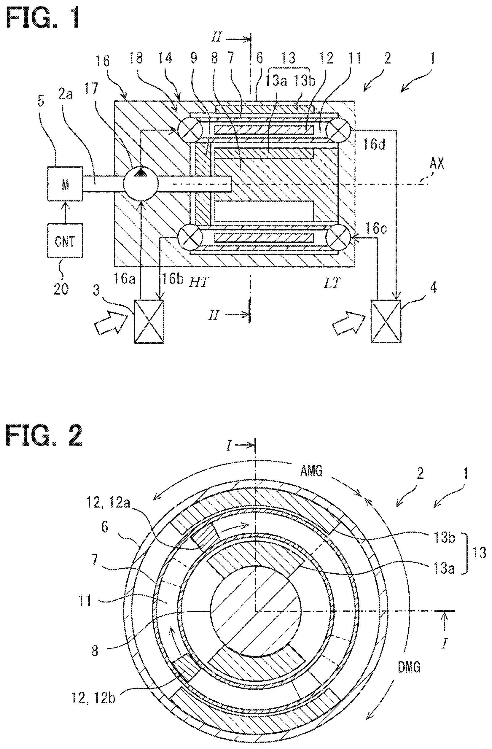
[0025] FIG. 1 and FIG. 2 show an air conditioner 1 according to a first embodiment. FIG. 1 shows a cross section taken along a line I-I of FIG. 2. FIG. 2 shows a cross section taken along a line II-II of FIG. 1. The air conditioner 1 is one of thermal devices. The air conditioner 1 includes a magneto caloric heat pump device 2. The magneto caloric heat pump device 2 is also referred to as an MHP (Magneto-caloric effect Heat Pump) device 2. The MHP device 2 provides a thermomagnetic cycle device.
[0026] In this specification the term "heat pump device" is used in a broad sense. That is, the term "heat pump device" includes both a device utilizing cold energy obtained by the heat pump device and a device utilizing hot energy obtained by the heat pump device. Devices that utilize cold energy may also be referred to as refrigeration cycle devices. Hence, in this specification the term "heat pump device" is used as a concept encompassing a refrigeration cycle device.
[0027] The air conditioner 1 has a heat exchanger 3 provided on a high temperature side, i.e., hot side, of the MHP device 2. The heat exchanger 3 provides heat exchange between a hot end HT of the MHP device 2 and a medium, e.g., air. The heat exchanger 3 is mainly used to radiate heat. In the illustrated example, the heat exchanger 3 provides heat exchange between the heat transport medium of the MHP device 2 and the air. The heat exchanger 3 is one of high temperature system devices in the air conditioner 1. The heat exchanger 3 is installed, for example, in a room of a vehicle and heats air by heat exchange with air for air conditioning.
[0028] The air conditioner 1 has a heat exchanger 4 provided on a low temperature side, i.e., cold side, of the MHP device 2. The heat exchanger 4 provides heat exchange between a cold end LT of the MHP device 2 and a medium, e.g., air. The heat exchanger 4 is mainly used to absorb heat. In the illustrated example, the heat exchanger 4 provides heat exchange between the heat transport medium of the MHP device 2 and the heat source medium. The heat exchanger 4 is one of low temperature system devices in the air conditioner 1. The heat exchanger 4 is installed, for example, outside the vehicle and exchanges heat with the outside air.
[0029] The MHP device 2 has a rotary shaft 2a for driving the MHP device 2. The rotary shaft 2a is operatively connected to a power source 5. Thus, the MHP device 2 is rotationally driven by the power source 5. The power source 5 provides rotational power to the MHP device 2. The power source 5 is the only power source of the MHP device 2. The power source 5 is provided by a rotary device such as an electric motor or an internal combustion engine. An example of a power source is a motor driven by a battery mounted on a vehicle.
[0030] The MHP device 2 comprises a housing 6. The housing 6 supports the rotary shaft 2a in a rotatable manner. The MHP device 2 includes an element bed 7. The element bed 7 is rotatably supported in the housing 6. The element bed 7 rotates by receiving a rotational force directly or indirectly from the rotary shaft 2a. The element bed 7 is a rotary body rotated by the power source 5. The element bed 7 is a cylindrical member.
[0031] The element bed 7 forms a working chamber 11 in which the heat transport medium can flow. One work chamber 11 extends in the axial direction of the element bed 7. One work chamber 11 is open at both axial ends of the element bed 7. The element bed 7 may include a plurality of work chambers 11. The plurality of work chambers 11 are arranged along the rotational direction of the element bed 7.
[0032] The element bed 7 has a magneto caloric element 12. The magneto caloric element 12 is also referred to as a MCE (Magneto-Caloric Effect) element 12. The MHP device 20 utilizes the magneto caloric effect of the MCE element 32. The MHP device 2 generates the hot end HT and the cold end LT by the MCE element 12. The MCE element 12 is provided between the hot end HT and the cold end LT. In the illustrated example, the right side in the drawing is the cold end LT, and the left end in the drawing is the hot end HT. The element bed 7 is also called a rotor. The element bed 7 includes a work chamber 11 and the MCE element 12.
[0033] The MCE element 12 is disposed in the work chamber 11 so as to exchange heat with the heat transport medium. The MCE element 12 is fixed to and held by the element bed 7. The MCE element 12 is disposed along the flow direction of the heat transport medium. The MCE element 12 is elongated along the axial direction of the element bed 7. The element bed 7 may include a plurality of MCE elements 12. The plurality of MCE elements 12 are disposed apart from one another along the rotational direction of the element bed 7.
[0034] The MCE element 12 creates heat generation and heat adsorption in response to a change of strength of an external magnetic field. The MCE element 32 creates heat generation by applying the external magnetic field, and absorbs heat by removing the external magnetic field. When the electron spins become aligned in the magnetic field direction by the application of the external magnetic field, the MCE element 32 demonstrates a decreasing of magnetic entropy and an increasing of a temperature by releasing heat. When the electron spins become random by the removal of the external magnetic field, the MCE element 32 demonstrates an increasing of the magnetic entropy and a decreasing of a temperature by absorbing heat. The MCE element 32 is made of a magnetic material that demonstrates a high magneto caloric effect in a normal temperature range. For example, gadolinium-based materials or lanthanum-iron-silicon compounds can be used. Also, mixtures of manganese, iron, phosphorus and germanium can be used. As the MCE element 12, an element which absorbs heat by application of an external magnetic field and generates heat by removal of the external magnetic field may be used.
[0035] The MHP device 2 has a magnetic field module 8 disposed opposite to the element bed 7. The magnetic field module 8 is also called a stator. The magnetic field module 8 is provided by part of the housing 6. The magnetic field module 8 is disposed on a radial inside and/or on a radial outside of the element bed 7 and has a portion radially opposed to the element bed 7. These radially opposed portions are utilized to provide a magnetic field modulating device. The magnetic field module 8 is disposed at one axial end and/or the other axial end of the element bed 7 and has a portion axially opposed to the element bed 7. These axially opposed portions are utilized to provide a heat transport device, specifically, a channel switching mechanism.
[0036] The MHP device 2 includes a magnetic field modulation device 14 and a heat transport device 16 for causing the MCE element 12 to function as an element of an AMR (Active Magnetic Refrigeration) cycle. The magnetic field modulation device 14 is provided by the element bed 7 and the magnetic field module 8. The magnetic field modulation device 14 periodically increases and decreases the magnetic field by the relative rotational movement of the element bed 7 with respect to the magnetic field module 8. The magnetic field modulation device 14 is driven by the rotational power applied to the rotary shaft 2a. The fluctuation of the magnetic field can be created by relatively rotating only one or both of the element bed 7 and the magnetic field module 8. The element bed 7 provides a movable member. The magnetic field module 8 provides a stationary member.
[0037] The heat transport device 16 has a pump 17 and a channel switching mechanism 18. The channel switching mechanism 18 is provided by the element bed 7 and the magnetic field module 8. The channel switching mechanism 18 functions by the relative rotational movement of the element bed 7 with respect to the magnetic field module 8. The channel switching mechanism 18 switches the flow direction of the heat transport medium to the work chamber 11 and the MCE element 12 by switching the connection state of the work chamber 11 to a channel of the heat transport medium, i.e., a flow path of the heat transport medium.
[0038] The magnetic field modulation device 14 applies an external magnetic field to the MCE element 12 and increases or decreases the strength of the external magnetic field. The magnetic field modulation device 40 periodically switches between a magnetization state in which the MCE element 32 is in a strong magnetic field and a demagnetization state in which the MCE element 32 is in a weak magnetic field or a zero magnetic field. The magnetic field modulation device 14 modulates the external magnetic field so as to alternately and periodically perform a magnetization period AMG in which the MCE element 12 is placed in a strong external magnetic field, and a demagnetization period DMG in which the MCE element 12 is placed in an external magnetic field weaker than the magnetization period AMG. The magnetic field modulation device 14 repeats application and removal of the magnetic field to the MCE element 12 in synchronization with the reciprocal flow of the heat transport medium described later. The magnetic field modulation device 40 comprises a magnetic source, such as a permanent magnet or an electromagnet, for generating an external magnetic field. The magnetic source 13 includes an inner magnet 13a located on a radial inside of the element bed 7. The magnetic source 13 includes an outer magnet 13b located on a radial outside of the element bed 7.
[0039] Specifically, the magnetic field modulation device 14 alternately positions one work chamber 11 and the MCE element 12 at the first position and the second position. The magnetic field modulation device 14 positions the MCE element 12 at the first position in a strong magnetic field. The magnetic field modulation device 14 positions the MCE element 12 at the second position in a weak magnetic field or a zero magnetic field.
[0040] When the heat transport medium flows in a first direction along the MCE element 12, the magnetic field modulation device 14 positions the MCE element 12 at the first position so that the MCE element 12 is positioned in the strong magnetic field. The first direction is a direction from the cold end LT toward the hot end HT. When one end of the work chamber 11 communicates with a suction port of the pump 17 and the other end of the work chamber 11 communicates with a discharge port of the pump 17, the magnetic field modulation device 14 positions the MCE element 12 in the work chamber 11 at the first position so that the MCE element 12 is positioned in a strong magnetic field.
[0041] When the heat transport medium flows along the MCE element 12 in a second direction opposite to the first direction, the magnetic field modulation device 14 positions the MCE element 12 in the work chamber 11 at the second position so that the MCE element 12 is positioned in a weak magnetic field or a zero magnetic field. The second direction is a direction from the hot end HT to the cold end LT. When one end of the work chamber 11 communicates with the discharge port of the pump 17 and the other end of the work chamber 11 communicates with the suction port of the pump 17, the magnetic field modulation device 14 positions the MCE element 12 at the second position so that the MCE element 12 is positioned in a weak magnetic field or a zero magnetic field.
[0042] The heat transport device 16 includes a heat transport medium for transporting heat released or absorbed by the MCE element 12 and a fluid device for flowing the heat transport medium. The heat transport device 16 is a device for flowing the heat transport medium along the MCE element 12 which performs heat-exchange with the MCE element 12. The heat transport device 16 causes the heat transport medium to flow back and forth along the MCE element 12. The heat transport device 16 generates a reciprocating flow of the heat transport medium in synchronization with the change of the external magnetic field by the magnetic field modulation device 14. The heat transport device 16 switches the flow direction of the heat transport medium in synchronization with increase and decrease of the magnetic field by the magnetic field modulation device 14.
[0043] The heat transport medium which exchanges heat with the MCE element 12 is called a primary medium. The primary medium can be provided by a fluid such as antifreeze, water, oil and the like. The heat transport device 16 comprises the pump 17 for flowing the heat transport medium. The pump 17 is a unidirectional pump that flows the heat transport medium in one direction. The pump 17 has a suction port for sucking the heat transport medium and a discharge port for discharging the heat transport medium. The pump 17 is disposed above the annular flow path of the heat transport medium. The pump 17 produces a unidirectional flow of the heat transport medium in the annular flow path. The pump 17 is driven by the rotary shaft 2a. The pump 17 is a positive displacement pump.
[0044] The heat transport device 16 includes a channel switching mechanism 18. The channel switching mechanism 18 switches the channel of the heat transport medium to the work chamber 11 so as to reverse the flow direction of the heat transport medium with respect to one work chamber 11 and one MCE element 12. In other words, the channel switching mechanism 18 reverses the arrangement of the working chamber 11 in the unidirectional flow of the heat transport medium generated by the unidirectional pump 17 with respect to the flow direction. The channel switching mechanism 18 alternately positions one working chamber 11 in the forward path and the return path in an annular flow path including the pump 17. The channel switching mechanism 18 switches a connection relationship between a pair of one working chamber 11 and one MCE element 12 and an annular channel including the pump 17 into at least two states. In the first state, one end of the work chamber 11 communicates with the suction port of the pump 17, and the other end of the work chamber 11 communicates with the discharge port of the pump 17. In the second state, one end of the work chamber 11 is in communication with the discharge port of the pump 17 and the other end of the work chamber 11 is in communication with the suction port of the pump 17.
[0045] Specifically, the channel switching mechanism 18 alternately positions one work chamber 11 and the MCE element 12 at the first position and the second position. The channel switching mechanism 18 brings the work chamber 11 accommodating the MCE element 12 into communication with the flow path so that the heat transport medium flows in the first direction along the MCE element 12 at the first position. The channel switching mechanism 18 brings the work chamber 11 accommodating the MCE element 12 into communication with the flow path so that the heat transport medium flows in the second direction opposite to the first direction along the MCE element 12 at the second position. The channel switching mechanism 18 switches the connection state between the flow path of the heat transport medium including the pump 17 and the MCE element 12, that is, the work chamber 11 so that the heat transport medium flows back and forth to the MCE element 12.
[0046] When one NICE element 12 is in the first position, the channel switching mechanism 18 communicates the work chamber 11 containing the MCE element 12 and the channel (flow path) so that the heat transport medium flows in the first direction along the MCE element 12. When one MCE element 12 is in the first position, the channel switching mechanism 18 communicates one end of the work chamber 11 accommodating the NICE element 12 with the suction port of the pump 17, and communicates the other end of the work chamber 11 accommodating the MCE element 12 with the discharge port of the pump 17.
[0047] When one MCE element 12 is in the second position, the channel switching mechanism 18 communicates the work chamber 11 containing the MCE element 12 and the channel (flow path) so that the heat transport medium flows in the second direction opposite to the first direction along the MCE element 12. When one MCE element 12 is in the second position, the channel switching mechanism 18 communicates one end of the work chamber 11 accommodating the MCE element 12 with the discharge port of the pump 17, and communicates the other end of the work chamber 11 accommodating the MCE element 12 with the suction port of the pump 17.
[0048] The MHP device 2 has a hot end inlet 16a for receiving the heat transport medium from the heat exchanger 3. The hot end inlet 16a can communicate with the suction port of the pump 17. The MHP device 2 has a hot end outlet 16b for supplying the heat transport medium to the heat exchanger 3. The hot end outlet 16b can communicate with one end of the work chamber 11 at the first position. The MHP device 2 has a cold end inlet 16c for receiving the heat transport medium from the heat exchanger 4. The cold end inlet 16c can communicate with the other end of the work chamber 11 at the first position. The MHP device 2 has a cold end outlet 16d for supplying the heat transport medium to the heat exchanger 4. The cold end outlet 16d can communicate with the other end of the work chamber 11 at the second position. One end of the work chamber 11 at the second position can communicate with the discharge port of the pump 17.
[0049] The MHP device 2 has a central axis AX. The element bed 7 and the magnetic field module 8 are circular columnar shape or cylindrical shape with respect to the central axis AX.
[0050] The MHP device 2 includes a controller (CNT) 20. The controller 20 controls at least the power source 5. The controller 20 controls the number of rotations of the power source 5. In addition, the controller 20 controls functions as the air conditioner 1. The controller 20 controls, for example, an amount of air blown to the heat exchanger 3 and/or the heat exchanger 4.
[0051] The controller 20 is an electronic control unit. The controller 20 provides a control system for the thermomagnetic cycle system. The controller 20 has at least one arithmetic processing unit (CPU) and at least one memory device (MMR) as a storage medium for storing programs and data. The control system is provided by a microcomputer comprising a computer readable storage medium. The storage medium is a non-transitional tangible storage medium that temporarily stores a computer readable program. The storage medium may be provided as a semiconductor memory, a magnetic disk, or the like. The control system may be provided by one computer or a group of computer resources linked via a data communication device. The program is executed by the control system to cause the control system to function as a device described in the present specification and to cause the control system to function to perform the methods described in the present specification.
[0052] Software stored in a tangible memory and a computer executing the software, only the software, only hardware, or combination of them may be possible to provide a method and/or function provided by the control system. For example, the control system can be provided by a logic called if-then-else type, or a neural network tuned by machine learning. For example, if the control system is provided by an electronic circuit that is hardware, the control device may be provided by a digital circuit or an analog circuit that includes a large number of logic circuits.
[0053] FIG. 3 shows a pressure distribution of the heat transport medium. The MHP device 2 provides a circulation path for the heat transport medium. The pump 17 is disposed in a circulation path. Furthermore, the channel switching mechanism 18 is disposed in a flow path extending between the element bed 7 and the magnetic field module 8, that is, between the movable member and the stationary member. The channel switching mechanism 18 has a plurality of valves. A plurality of valves are arranged at the inlet and the outlet of the plurality of element beds 7. Here, in order to make the explanation easy to understand, two unit channels (element bed 7) providing circulation paths and four related valves will be described. The channel switching mechanism 18 has at least an inlet valve 18a and an outlet valve 18b at the hot end HT. The channel switching mechanism 18 has at least the outlet valve 18e and the inlet valve 18f at the cold end LT.
[0054] The heat exchanger 3 produces a pressure drop PDe. The heat exchanger 4 also produces a pressure drop PDe. The heat exchanger 3 and the heat exchanger 4 may produce different pressure losses. The pump 17 sucks the heat transport medium at a suction pressure Ps. The pump 17 pressurizes the heat transport medium. The pump 17 discharges the heat transport medium of the discharge pressure Pd. The unit channel (element bed 7) produces a pressure loss PDd.
[0055] The heat transport medium is supplied at a pressure P1 toward one unit channel. At this time, the pressure P1 acts on the inlet valve 18a. The seal mechanism provided by the inlet valve 18a provides a seal that can function properly under the pressure P1. The heat transport medium flows out of one unit channel at a pressure P2. The pressure P2 acts on the outlet valve 18e. The seal mechanism provided by the outlet valve 18e provides a seal that can function properly under the pressure P2.
[0056] The pressure P1 is higher than the pressure P2 (P1>P2). Therefore, the inlet valve 18a is required to have higher sealing performance than the outlet valve 18e. On the contrary, the outlet valve 18e can perform proper function with a sealing property lower than that of the inlet valve 18a. In other words, even if the pressing force between the stationary member and the movable member in the outlet valve 18e is smaller than the pressing force between the stationary member and the movable member in the inlet valve 18a, the outlet valve 18e can perform proper function. The inlet valve 18a and the outlet valve 18e provide an inlet and an outlet for the flow of the heat transport medium in one direction of the reciprocating flow. One direction is a direction from the hot end HT to the cold end LT. The inlet valve 18a and the outlet valve 18e provide an inlet and an outlet associated with the common unit channel (element bed 7).
[0057] The heat transport medium is supplied at a pressure P3 toward one unit channel. At this time, the pressure P3 acts on the inlet valve 18f. The seal mechanism provided by the inlet valve 18f provides a seal that can function properly under the pressure P3. The heat transport medium flows out of one unit channel at a pressure P4. The pressure P4 acts on the outlet valve 18b. The sealing mechanism provided by the outlet valve 18b provides a seal that can function properly under the pressure P4.
[0058] The pressure P3 is higher than the pressure P4 (P3>P4). Therefore, the inlet valve 18f is required to have higher sealing performance than the outlet valve 18b. On the contrary, the outlet valve 18b can perform proper function with a sealing property lower than that of the inlet valve 18f. In other words, even if the pressing force between the stationary member and the movable member in the outlet valve 18b is smaller than the pressing force between the stationary member and the movable member in the inlet valve 18f, the outlet valve 18b can perform proper function. The inlet valve 18f and the outlet valve 18b provide an inlet and an outlet for the flow of the heat transport medium in the other direction of the reciprocating flow. The other direction is a direction from the cold end LT to the hot end HT. The inlet valve 18f and the outlet valve 18b provide an inlet and an outlet associated with a common unit channel (element bed 7).
[0059] Focusing on the hot end HT or the cold end LT, at least a pair of an inlet valve and an outlet valve is disposed between the stationary member and the movable member. The channel switching mechanism 18 can include an even number of pairs of inlet and outlet valves. In this embodiment, two pairs of inlet and outlet valves are arranged as described below.
[0060] At one end, i.e., the hot end HT, the pressure P1 is higher than the pressure P4 (P1>P4). Therefore, the inlet valve 18a is required to have higher sealing performance than the outlet valve 18b. On the contrary, the outlet valve 18b can perform proper function with lower sealing performance than that of the inlet valve 18a. In other words, even if the pressing force between the stationary member and the movable member in the outlet valve 18b is smaller than the pressing force between the stationary member and the movable member in the inlet valve 18a, the outlet valve 18b can perform proper function. In this embodiment, the pressing force F1 at the inlet valve 18a is larger than the pressing force F2 at the outlet valve 18d (F1>F2). Thereby, the mechanical loss in the outlet valve 18b is suppressed.
[0061] The inlet valve 18a and the outlet valve 18b provide an inlet and an outlet for the reciprocating flow at one end, i.e., the hot end HT. The inlet valve 18a provides an inlet for the flow from the hot end HT to the cold end LT. The outlet valve 18b provides an outlet for the flow from the cold end LT to the hot end HT. The inlet valve 18a and the outlet valve 18b simultaneously provide an inlet and an outlet associated with different unit channels.
[0062] At the other end, i.e., at the cold end LT, the pressure P2 is higher than the pressure P3 (P2>P3). For this reason, the outlet valve 18e is required to have higher sealing performance than that of the inlet valve 18f. On the contrary, the inlet valve 18f can perform proper function with a lower sealing performance than that of the outlet valve 18e. In other words, even if the pressing force between the stationary member and the movable member in the inlet valve 18f is smaller than the pressing force between the stationary member and the movable member in the outlet valve 18e, the inlet valve 18f can perform proper function. In this embodiment, the pressing force F5 at the outlet valve 18e is larger than the pressing force F6 at the inlet valve 18f (F5>F6). Thereby, the mechanical loss in the inlet valve 18f is suppressed.
[0063] The inlet valve 18f and the outlet valve 18e provide an inlet and an outlet for the reciprocating flow at the other end, i.e., the cold end LT. The inlet valve 18 f provides an inlet for flow from the cold end LT to the hot end HT. The outlet valve 18e provides an outlet for the flow from the hot end HT to the cold end LT. The inlet valve 18f and the outlet valve 18e provide an inlet and an outlet associated with different unit channels.
[0064] FIGS. 4 and 5 show the channel switching mechanism 18 at the hot end HT and the sealing mechanism associated therewith. The work chamber 11 provided by the element bed 7 provides a plurality of axial flow channels. In the drawing, one unit channel is illustrated by a mass of the MCE element 12. The name "one element bed 7" may refer to this unit channel.
[0065] The channel switching mechanism 18 includes a valve element 19 disposed opposite to the element bed 7 which is a movable member. The valve element 19 is a stationary member. The valve element 19 is disposed opposite to the end of the element bed 7. The valve element 19 comes in contact with the end face of the element bed 7 in a sliding manner. The valve element 19 provides a plurality of ports for providing the inlet valve 18a and the outlet valve 18b. The valve element 19 comprises a plurality of segments 19a, 19b, 19c and 19d. The plurality of segments 19a, 19b, 19c and 19d are annularly arranged. Each of the plurality of segments 19a, 19b, 19c and 19d occupies a fan-shaped area. The plurality of segments 19a, 19b, 19c and 19d are held so as to be relatively movable in the axial direction. The plurality of segments 19a, 19b, 19c and 19d are held immovable in the circumferential direction.
[0066] The segment 19a provides the inlet valve 18a. The inlet valve 18a opens to the unit channel when the segment 19a and the unit channel are opposed to each other. The inlet valve 18a closes to the unit channel when the segment 19a and the unit channel do not face each other and are separated. The segment 19b provides an outlet valve 18b. The outlet valve 18b opens to the unit channel when the segment 19b and the unit channel are opposed to each other. The outlet valve 18b closes with respect to the unit channel when the segment 19b and the unit channel do not face each other and are separated. As a result, the channel switching mechanism 18 forms the inlet valve 18a and the outlet valve 18b at one end of one unit channel. In this embodiment, two inlet valves and two outlet valves are provided by the four segments 19a, 19b, 19c and 19d. Thus, the channel switching mechanism 18 forms two inlet valves and two outlet valves at one end of one unit channel. The two inlet valves 18a and 18c and the two outlet valves 18b and 18d are alternately opened and closed with respect to one unit channel to provide the reciprocating flow.
[0067] The channel switching mechanism 18 has the biasing mechanism 30 for pressing the valve element 19 toward the element bed 7. The biasing mechanism 30 provides at least two different biasing forces. In this embodiment, the biasing force is also called pressing force. The biasing mechanism 30 has four biasing elements 31, 32, 33 and 34 associated with each of the four segments 19a, 19b, 19c and 19d. In this embodiment, the segments 19a and 19c may be biased by a common biasing element since they provide the inlet valves. Similarly, the segments 19b and 19d may be biased by a common biasing element to provide the outlet valves.
[0068] Each of the biasing elements 31, 32, 33 and 34 has a variable element 35 and an invariable element 36. The variable element 35 varies the biasing force according to the pressure of the heat transport medium. The variable element 35 is provided by a pressure sensitive element whose dimension, i.e., axial length, varies in response to the pressure of the heat transport medium. The variable element 35 is provided by a balloon. The variable element 35 axially expands under the pressure of the heat transport medium when the pressure of the heat transport medium exceeds the predetermined pressure. The variable element 35 contracts in the axial direction under the pressure of the heat transport medium when the pressure of the heat transport medium falls below a predetermined pressure. The predetermined pressure can be set between the pressure P1 and the pressure P4. The invariable element 36 is an elastic member that provides invariable resiliency. The invariable element 36 generates a biasing force without depending on a pressure of the heat transport medium. The invariable element 36 can be provided, for example, by a mechanical coil spring. The invariable element 36 is a preloaded compression coil spring.
[0069] When the pressure P1 acts on the variable element 35, the variable element 35 elongates in the axial direction. As a result, the segment 19a is pressed toward the element bed 7 by the pressing force F1. The pressing force F1 produces a surface pressure that provides sealing between the segment 19a and the element bed 7. When the pressure P4 acts on the variable element 35, the variable element 35 comes in contract in the axial direction. As a result, the segment 19b is pressed toward the element bed 7 by the pressing force F2. The pressing force F2 produces a surface pressure that provides sealing between the segment 19b and the element bed 7. The pressing force F1 is larger than the pressing force F2 (F1>F2).
[0070] When the element bed 7, which is a movable member, rotates, the unit channel sequentially passes over the plurality of segments 19a, 19b, 19c, and 19d. When the unit channel is located above the segments 19a and 19c, the segments 19a and 19c are pressed toward the element bed 7 by the pressing force F1. When the unit channel is located above the segments 19b and 19d, the segments 19b and 19d are pressed toward the element bed 7 with the pressing force F2. As a result, compared with the case where the entire valve element 19 is pressed toward the element bed 7 by the pressing force F1, the pressing force is suppressed in the section of the segments 19b and 19d. As a result, mechanical loss is suppressed.
[0071] FIGS. 6 and 7 show the channel switching mechanism 18 at the cold end LT and the sealing mechanism associated therewith. The valve element 19 provides a plurality of ports for providing the inlet valve 18f and the outlet valve 18e. The valve element 19 comprises a plurality of segments 19e, 19f, 19g and 19h.
[0072] The segment 19e provides the outlet valve 18e. The outlet valve 18e opens to the unit channel when the segment 19e and the unit channel are opposed to each other. The outlet valve 18e closes to the unit channel when the segment 19e and the unit channel do not face each other and are separated. The segment 19f provides the inlet valve 18f. The inlet valve 18f opens to the unit channel when the segment 19f and the unit channel are opposed to each other. The inlet valve 18f closes to the unit channel when the segment 19f and the unit channel do not face each other and are separated. As a result, the channel switching mechanism 18 forms the outlet valve 18e and the inlet valve 18f at the other end of one unit channel. In this embodiment, two inlet valves 18f and 18h and two outlet valves 18e and 18g are provided by four segments 19e, 19f, 19g and 19h. Thus, the channel switching mechanism 18 forms two inlet valves and two outlet valves on the other end of one unit channel. The two inlet valves and the two outlet valves are alternately opened and closed with respect to one unit channel to provide the reciprocating flow. The channel switching mechanism 18 at the hot end HT and the channel switching mechanism 18 at the cold end LT are arranged symmetrically to each other.
[0073] At the cold end LT, the predetermined pressure of the variable element 35 is set between the pressure P2 and the pressure P3. When the pressure P2 acts on the variable element 35, the variable element 35 elongates in the axial direction. As a result, the segments 19e and 19g are pressed toward the element bed 7 by the pressing force F5. The pressing force F5 produces a surface pressure that provides sealing between the segments 19e and 19g and the element bed 7. When the pressure P3 acts on the variable element 35, the variable element 35 comes contract in the axial direction. As a result, the segments 19f and 19h are pressed toward the element bed 7 by the pressing force F6. The pressing force F6 produces a surface pressure that provides sealing between the segments 19f and 19h and the element bed 7. The pressing force F5 is larger than the pressing force F6 (F5>F6). Even in the cold end LT, the pressing force is suppressed in a section of the segments 19f and 19h as compared with the case where the entire valve element 19 is pressed toward the element bed 7 by the pressing force F5. As a result, mechanical loss is suppressed.
[0074] With regard to the MHP device 2, the description of JP2016-1101A may be referred to. The entire contents of JP2016-1101A are incorporated by reference. Further, with regard to the element bed 7 and the unit channel, U.S. Pat. No. 8,844,453 may be referred to. The entire contents of U.S. Pat. No. 8,444,453 are incorporated by reference. According to the embodiment described above, the channel switching mechanism 18 forms the inlet valve 18a and the outlet valve 18b at one end (the hot end HT) of one unit channel. The biasing mechanism 30 provides biasing force for maintaining the inlet valve 18a and the outlet valve 18b in the closed state. Moreover, the biasing mechanism 30 applies different biasing forces F1 and F2 to the inlet valve 18a and the outlet valve 18b. The magnitude relationship (F1>F2) of the two biasing forces is the same as the magnitude relationship (P1>P4) between the pressure P1 of the heat transport medium acting on the inlet valve 18a and the pressure P4 of the heat transport medium acting on the outlet valve 18b.
[0075] Furthermore, the absolute value of the biasing force is adjusted by the variable element 35. Moreover, the biasing force is set in proportion to the pressure. For this reason, the valve-closing performance which withstands the pressure of the heat transport medium, i.e., sealing performance, is obtained.
[0076] The channel switching mechanism 18 forms the inlet valve 18f and the outlet valve 18e at the other end (the cold end LT) of one unit channel. The biasing mechanism 30 provides a biasing force for maintaining the inlet valve 18f and the outlet valve 18e in a closed state. Moreover, the biasing mechanism 30 applies different biasing forces F5 and F6 to the inlet valve 18f and the outlet valve 18e. The magnitude relationship (F5>F6) of the two biasing forces is the same as the magnitude relationship (P2>P3) between the pressure P3 of the heat transport medium acting on the inlet valve 18f and the pressure P2 of the heat transport medium acting on the outlet valve 18e.
[0077] As a result, mechanical loss can be suppressed. Moreover, the valve element 19 comprises a plurality of segments. The multiple segments allow different pressing forces and reliably suppress mechanical losses.
Second Embodiment
[0078] This embodiment is a modification in which the preceding embodiment is a fundamental form. In the above embodiment, the MHP device 2 has a single pump 17. Alternatively, the MHP device 2 may be provided with a plurality of pumps 17 and 217a. The pump 17 is provided at one end of the unit channel. The pump 217a is provided at the other end of the unit channel.
[0079] FIG. 8 shows pressure distribution in this embodiment. The MHP device 2 also has a pump 217a in a path on a side to the cold end LT. The pump 17 and the pump 217a are the same pump. The pump 217a applies a pressure P2a to the outlet valve 18e. The pump 217a applies a pressure P3a to the inlet valve 18f.
[0080] In this case, the pressure P2a acting on the outlet valve 18e is higher than the pressure P3a acting on the inlet valve 18f. For this reason, the inlet valve 18f is required to have higher sealing performance than that of the outlet valve 18e. On the contrary, the outlet valve 18e can perform proper function with a sealing property lower than that of the inlet valve 18f. In other words, even if the pressing force between the stationary member and the movable member in the outlet valve 18e is smaller than the pressing force between the stationary member and the movable member in the inlet valve 18f, the outlet valve 18e can perform proper function. In this embodiment, the pressing force F6a at the inlet valve 18f is larger than the pressing force F5a at the outlet valve 18e (F5a<F6a). Thereby, the mechanical loss in the outlet valve 18e is suppressed. The inlet valve 18f and the outlet valve 18e provide an inlet and an outlet for the reciprocating flow at the other end, i.e, the cold end LT. The inlet valve 18f provides an inlet for flow from the cold end LT to the hot end HT. The outlet valve 18e provides an outlet for the flow from the hot end HT to the cold end LT. The inlet valve 18f and the outlet valve 18e are positioned opposite to different element beds 7.
[0081] FIG. 9 shows the channel switching mechanism 18 at the cold end LT and the sealing mechanism associated therewith. A difference from the preceding embodiments is the shape of the variable element 35 and the pressing forces F5a and F6a produced thereby. When the biasing mechanism 30 includes the variable element 35, a difference in pressing force occurs. The segments 19e and 19g are pressed toward the element bed 7 by the pressing force F5a. The segments 19f and 19h are pressed toward the element bed 7 by the pressing force F6a. The pressing force F6a is larger than the pressing force F5a (F5a<F6a).
[0082] According to this embodiment, the channel switching mechanism 18 forms the inlet valve 18f and the outlet valve 18e at the other end (the cold end LT) of one unit channel. The biasing mechanism 30 provides a biasing force for maintaining the inlet valve 18f and the outlet valve 18e in a closed state. Moreover, the biasing mechanism 30 applies different biasing forces F5 and F6 to the inlet valve 18f and the outlet valve 18e. The magnitude relationship (F5a<F6a) of the two biasing forces is the same as the magnitude relationship (P2a<P3a) between the pressure P3a of the heat transport medium acting on the inlet valve 18f and the pressure P2a of the heat transport medium acting on the outlet valve 18e. As a result, even if the pump 217a is provided, mechanical loss is suppressed.
Third Embodiment
[0083] This embodiment is a modification in which the preceding embodiment is a fundamental form. In the above embodiment, the biasing elements 31, 32, 33, 34 comprise both the variable element 35 and the invariable element 36. Alternatively, the biasing elements 31, 32, 33, 34 may comprise only the invariable element 36.
[0084] In FIG. 10, the functions of the plurality of segments 19a, 19b, 19c and 19d are fixed at the inlet or outlet. For example, the segment 19a continuously provides an inlet. The segment 19b continuously provides an exit. For this reason, the pressing force to be applied to the plurality of segments may be fixed. The biasing elements 31, 32, 33 and 34 then comprise only the invariable element 36. The invariable element 36 includes a first elastic member 336a for generating a pressing force F1 and a second elastic member 336b for generating a pressing force F2. The first elastic member 336a and the second elastic member 336b can be provided by coil springs having different spring constants or compression amounts. The first elastic member 336a and the second elastic member 336b are compression coil springs which are preloaded differently to generate the pressing forces F1 and F2. The first elastic member 336a applies the pressing force F1 stronger than the pressing force F2 to the segments 19a and 19c. The second elastic member 336b applies the pressing force F2 weaker than the pressing force F1 to the segments 19b and 19d. The biasing elements 31 and 33 each comprises a first resilient member 336a. The biasing elements 32 and 34 each comprises a second resilient member 336b. In this embodiment as well, similar to the previous embodiments, mechanical losses can be suppressed. The structure of this embodiment can be adopted for the hot end HT and/or the cold end LT.
Fourth Embodiment
[0085] This embodiment is a modification in which the preceding embodiment is a fundamental form. In the above embodiment, a coil spring is used as the invariable element 36. Alternatively, the invariable element may be provided by a variety of elastic members. For example, a resin material such as rubber or elastomer may be used as the invariable element.
[0086] In FIG. 11, the invariable element 36 includes a first elastic member 436a for generating a pressing force F1 and a second elastic member 436b for generating a pressing force F2. The first elastic member 436a and the second elastic member 436b can be provided by rubber masses different in elasticity. In this embodiment as well, similar to the previous embodiments, mechanical losses can be suppressed.
Fifth Embodiment
[0087] This embodiment is a modification in which the preceding embodiment is a fundamental form. In the above embodiment, the variable element 35 is provided by a mechanical element. Alternatively, the variable element 35 may be provided by a variety of variable mechanisms. For example, an electromagnetic movable mechanism can be used as a variable element.
[0088] In FIG. 12, the variable element 35 is provided by an electromagnetic solenoid. The electromagnetic solenoid includes a stator 537 that includes an electromagnetic coil. The electromagnetic solenoid includes an armature 538 that contracts when it is attracted by the electromagnetic force generated by exiting the stator 537, and extends when it is freed by a spring force by de-energizing the stator 537. The armature 538 is connected to the invariable element 36. The electromagnetic solenoid can be controlled by the controller 20. In this embodiment as well, similar to the previous embodiments, mechanical losses can be suppressed.
Sixth Embodiment
[0089] This embodiment is a modification in which the preceding embodiment is a fundamental form. In the above embodiment, the movable member is provided by the element bed 7, and the stationary member is provided by the magnetic field module 8. Alternatively, the element bed 7 may provide a stationary member, and the magnetic field module 8 may provide a movable member.
[0090] FIG. 13, FIG. 14 and FIG. 15 show the air conditioner 1 and the MHP device 2 of this embodiment. FIG. 13 shows a cross section taken along a line XIII-XIII in FIG. 14 and FIG. 15. FIG. 14 shows a cross section taken along a line XIV-XIV of FIG. 13. FIG. 15 shows a cross section taken along a line XV-XV in FIG. 13.
[0091] In FIG. 13, the MHP device 2 includes the element bed 7, the magnetic field modulation device 14, and the heat transport device 16. The element bed 7 accommodates the MCE element 12. The element bed 7 provides a plurality of unit channels. The magnetic field modulation device 14 supplies an external magnetic field to the element bed 7. The magnetic field modulation device 14 modulates an intensity of the external magnetic field so that the MCE element 12 alternately demonstrates heat generation and heat absorption by the magneto caloric effect. The heat transport device 16 provides a reciprocating flow of the heat transport medium to perform a heat exchange with the MCE element 12. The magnetic field modulation device 14 and the heat transport device 16 are synchronized with each other. The MHP device 2 is operated to provide an AMR cycle.
[0092] The magnetic field modulation device 14 is provided by the element bed 7 and the magnetic field module 8. The element bed 7 is a stationary member. The element bed 7 is also called a stator. The magnetic field module 8 is a movable member. The magnetic field module 8 is also called a rotor. The magnetic field module 8 has an inner magnet 613a and an outer magnet 613b as the magnetic source 13. The inner magnet 613a is fixed to an inner yoke 608a that rotates with the rotary shaft 2a. The outer magnet 613b is fixed to an outer yoke 608b that rotates with the rotary shaft 2a.
[0093] The channel switching mechanism 18 includes a switching valve. The switching valve is disposed in the body 618k fixed to the element bed 7. The body 618k is a part of a stationary member. The switching valve is provided by a plurality of on-off valves. The switching valve includes two sets of on-off valves disposed at both ends of one unit channel. One set of on-off valves includes an inlet valve 618a and an outlet valve 618b. In FIG. 13, two unit channels are exemplarily illustrated, and four sets of eight on-off valves are illustrated.
[0094] FIG. 14 shows a plurality of unit channels provided by the element bed 7. The plurality of unit channels are illustrated as a first channel #1 to an eighth channel #8. The number of unit channels illustrated is merely an example, and is not limited to eight.
[0095] In this embodiment, the channels from the first channel #1 to the eighth channel #8 are stationary. The magnetic source 613 rotationally moves. With the movement of the magnetic source 613, the magnetization period AMG and the demagnetization period DMG move. As a result, one unit channel is alternately placed in the magnetization period AMG and the demagnetization period DMG. For example, at the time of illustration, the first channel #1 is positioned in the magnetization period AMG, and the second channel #2 is positioned in the demagnetization period DMG. When the magnetic source 13 rotates by n/2 from the time shown, the first channel #1 is positioned in the demagnetization period DMG, and the second channel #2 is positioned in the magnetization period AMG.
[0096] FIG. 15 shows a plurality of sets of on-off valves associated with a plurality of unit channels at the hot end HT. The symbol "=" indicates the close state. The symbol " " and the symbol "X" indicate the open state. The symbol " " indicates the direction of flow from the paper surface. The symbol "X" indicates the direction of flow toward the paper surface.
[0097] In this embodiment, the element bed 7 provides eight unit channels. The channel switching mechanism 18 has eight sets of on-off valves. For example, the inlet valve 618a and the outlet valve 618b are associated with the hot end HT of the first channel #1. Similarly, the inlet valve 618a and the outlet valve 618b are associated with the hot end HT of the second channel #2.
[0098] The plurality of sets of on-off valves are driven to open and close so as to supply a reciprocating flow in the plurality of unit channels. Switching between valve opening and valve closing is synchronized with switching between the magnetization period AMG and the demagnetization period DMG. The plurality of on-off valves are driven by the plurality of cam mechanisms 618m and 618n. The switching of the flow direction of the reciprocating flow and the switching of the magnetization period AMG and the demagnetization period DMG may be adjusted in phase by the phase adjuster.
[0099] One set of two on-off valves, i.e., the inlet valve 618a and the outlet valve 618b, are alternately opened and closed. For example, the outlet valve 618b is closed while the inlet valve 618a of the first channel #1 is open. While the inlet valve 618a of the first channel #1 is closed, the outlet valve 618b is opened. Further, the open/close states of the inlet valve 618a and the outlet valve 618b are alternately switched. For example, at the time shown, the inlet valve 618a of the first channel #1 positioned in the magnetization period AMG is opened and the outlet valve 618b is closed. Thus, the channel switching mechanism 18 supplies the flow of the heat transport medium in the first direction to the first channel #1. When the magnetic source 13 rotates by .pi./2 from the illustrated time point, the inlet valve 618a of the first flow path #1 positioned in the demagnetization period DMG is closed and the outlet valve 618b is opened. Thus, the channel switching mechanism 18 supplies the flow of the heat transport medium in the second direction opposite to the first direction to the first channel #1.
[0100] Returning to FIG. 13, the channel switching mechanism 18 includes a mechanical link mechanism for driving the switching valve by the rotary shaft 2a. The mechanical link mechanism has a plurality of cam mechanisms 618m and 618n. The plurality of cam mechanisms 618m and 618n drive four on-off valves arranged on both sides of one unit channel so as to alternately switch the flow direction of the heat transport medium.
[0101] The plurality of cam mechanisms 618m and 618n drive the plurality of on-off valves alternately and complementarily. The term "alternating" refers to the inlet valve 618a and the outlet valve 618b being alternately opened and closed. The term "complementary" refers to the relative relationship between the on-off valve at the hot end HT and the on-off valve at the cold end LT. That is, the term "complementary" indicates switching between the following state (1) and the following state (2). In the state of (1), the inlet valve 618a of the hot end HT and the outlet valve 618b of the cold end LT are simultaneously opened, and the inlet valve 618a of the cold end LT and the outlet valve 618b of the hot end HT are simultaneously closed. In the state of (2), the inlet valve 618a of the cold end LT and the outlet valve 618b of the hot end HT are simultaneously opened, and the inlet valve 618a of the hot end HT and the outlet valve 618b of the cold end LT are simultaneously closed.
[0102] The cam mechanism 618m produces a first stroke ST1. The cam mechanism 618m drives the inlet valve 618a. The inlet valve 618a is switched between the open state and the closed state by the first stroke ST1. The cam mechanism 618n produces a second stroke ST2. The cam mechanism 618n drives the outlet valve 618b. The outlet valve 618b is switched between the open state and the closed state by the second stroke ST2. The first stroke ST1 is larger than the second stroke ST2 (ST1>ST2). The difference between the first stroke ST1 and the second stroke ST2 is used as the difference in the compression amount of the seal member described later.
[0103] Also in this embodiment, pressure distribution occurs in the flow path due to the position of the pump 17 and the pressure loss of each part. The pressure P1 acts on the inlet valve 618a of the hot end HT. On the other hand, the pressure P4 acts on the outlet valve 618b of the hot end HT. The pressure P1 is higher than the pressure P4. The force for the outlet valve 618b to maintain the closed state against the pressure P4 is smaller than the force for the inlet valve 618a to maintain the closed state against the pressure P1. Thus, by adjusting the force applied to the outlet valve 618b to be smaller than the force applied to the inlet valve 618a, mechanical losses are suppressed.
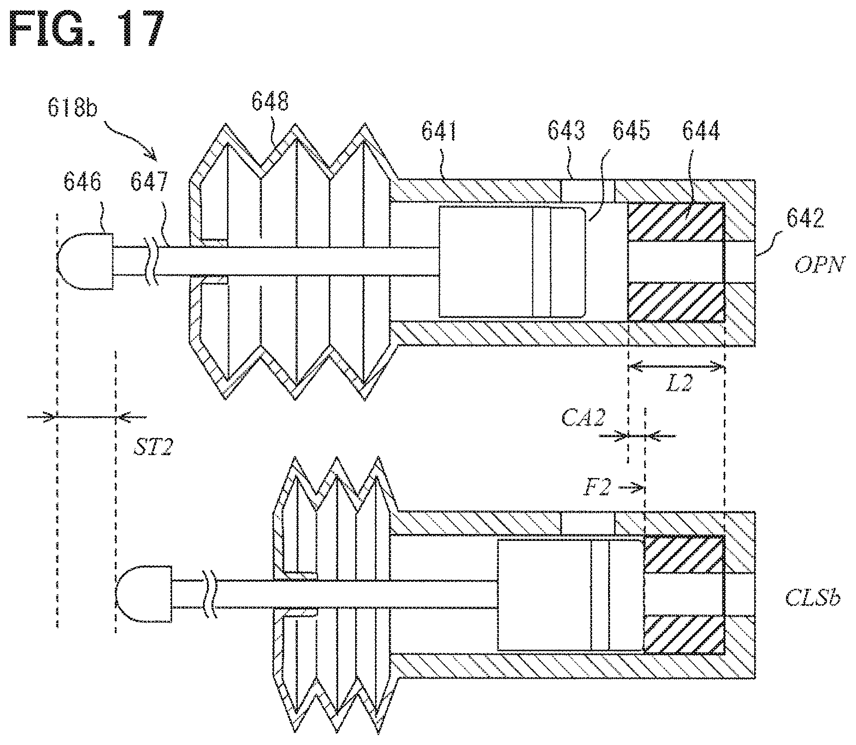
[0104] FIG. 16 shows the on-off valve as the inlet valve 618a at the hot end HT. FIG. 17 shows the on-off valve as the outlet valve 618b at the hot end HT. In FIGS. 16 and 17, the inlet valve 618a and the outlet valve 618b have a housing 641, ports 642 and 643, seal members 644a and 644b, a plunger 645, a cam follower 646, a rod 647, and a movable flange 648. The housing 641 provides ports 642 and 643 used as an inlet and an outlet. The housing 641 accommodates the seal members 644a and 644b and the plunger 645. The seal members 644a and 644b are fixed in the housing 641. The plunger 645 is relatively movable within the housing 641. The cam follower 646 comes in contact with the cam surfaces of the cam mechanisms 618m and 618n. The rod 647 transmits the movement of the cam follower 646 to the plunger 645. The movable flange 648 seals between the housing 641 and the rod 647. The movable flange 648 is provided by a bellows or a diaphragm.
[0105] In FIG. 16, the inlet valve 618a at the hot end HT provides an open state OPN and a close state CLSa. The inlet valve 618a provides the open state OPN by the plunger 645 moving away from the seal member 644a. The seal member 644a in the open state OPN has an initial length L1. The inlet valve 618a provides a closed state CLSa by the plunger 645 contacting the seal member 644a and the plunger 645 compressing the seal member 644a. The compression amount CA1 of the seal member 644a in the close state CLSa is defined by the initial length L1 and the first stroke ST1. The amount of compression CA1 is the amount of compression necessary for the inlet valve 618a at the hot end HT to maintain a closed state under the pressure P1 of the heat transport medium. The close state CLSa is also referred to as a first close state CLSa. The compression amount CA1 is also referred to as a first compression amount CAL
[0106] In FIG. 17, the outlet valve 618b at the hot end HT provides an open state OPN and a close state CLSb. The outlet valve 618b provides the open state OPN by the plunger 645 separating from the seal member 644b. The seal member 644b in the open state OPN has an initial length L2. The initial length L2 is smaller than the initial length L1 (L1>L2). In the outlet valve 618b, the plunger 645 comes in contact with the seal member 644b, and the plunger 645 compresses the seal member 644b to provide the close state CLSb. The compression amount CA2 of the seal member 644b in the close state CLSb is defined by the initial length L2 and the second stroke ST2. The compression amount CA2 is a compression amount required for the outlet valve 618b at the hot end HT to maintain a closed state under the pressure P4 of the heat transport medium. The close state CLSb is also referred to as a second close state CLSb. The compression amount CA2 is also referred to as a second compression amount CA2.
[0107] In FIGS. 16 and 17, the first compression amount CA1 is larger than the second compression amount CA2 (CA1>CA2). As a result, the inlet valve 618a withstands the pressure P1, and the outlet valve 618b withstands the pressure P4. At the same time, the power for compressing the seal member 644b at the outlet valve 618b is suppressed. In this embodiment, the biasing mechanism 30 is provided by the initial lengths L1 and L2 of the sealing members 644a and 644b and the strokes ST1 and ST2 of the cam mechanisms 618m and 618n. This suppresses mechanical losses.
[0108] In this embodiment, the plurality of on-off valves and the biasing mechanism 30 at the hot end HT have been described in detail. This description may also be applied to the plurality of on-off valves and the biasing mechanism 30 at the cold end LT.
[0109] In FIG. 13, the MHP device 2 also has a channel switching mechanism 18 at the cold end LT. The channel switching mechanism 18 of the hot end HT and the channel switching mechanism 18 of the cold end LT are arranged symmetrically. For example, the outlet valve 618e and the inlet valve 618f are associated with the cold end LT of the first channel #1. Similarly, the outlet valve 618e and the inlet valve 618f are associated with the cold end LT of the second channel #2.
[0110] The plurality of pressure distributions described in the first and second embodiments are also applicable to this embodiment. That is, also in this embodiment, the pump can be disposed at the cold end LT. When the pump is not disposed at the cold end LT, the inlet valve 618f of the cold end LT can be provided based on FIG. 17, and the outlet valve 618e of the cold end LT can be provided based on FIG. 16. When the pump is disposed at the cold end LT, the inlet valve 618f of the cold end LT can be provided based on FIG. 16, and the outlet valve 618e of the cold end LT can be provided based on FIG. 17.
[0111] In the sixth embodiment, the biasing mechanism 30 creates the difference (CA1-CA2) of the compression amount of the seal members 644a and 644b by the difference of the initial length (L1-L2), and the difference between the strokes (ST1-ST2). Alternatively, the biasing mechanism 30 may create the difference in the amount of compression only by the difference in the initial length. Furthermore, the biasing mechanism 30 may create the difference in the amount of compression only by the difference in the stroke.
[0112] Also in this embodiment, the channel switching mechanism 18 forms an inlet valve 618a and an outlet valve 618b at one end of one unit channel. The biasing mechanism 30 provides biasing force for maintaining the inlet valve 18a and the outlet valve 18b in the close state. Moreover, the biasing mechanism 30 applies different biasing forces F1 and F2 to the inlet valve 18a and the outlet valve 18b. The magnitude relationship (F1>F2) of the two biasing forces is the same as the magnitude relationship (P1>P4) between the pressure P1 of the heat transport medium acting on the inlet valve 18a and the pressure P4 of the heat transport medium acting on the outlet valve 18b.
[0113] Patent Documents JP2012-229634A, JP2016-1101A, and U.S. Pat. No. 8,448,453 discloses prior art arrangements. In those arrangements, a sealing mechanism is required to suppress leakage of the heat transport medium. However, the sealing mechanism produces mechanical losses. The mechanical loss appears as a loss of power to drive the movable member. For this reason, the thermomagnetic cycle device with small mechanical loss is required. In one form, for example, the heat transport medium may flow through both the movable member and the stationary member. In this case, the sealing mechanism between the movable member and the stationary member creates a mechanical loss. In another form, for example, an on-off valve that controls the flow of the heat transport medium may be disposed in the movable member or the stationary member. In this case, the sealing mechanism of the on-off valve produces mechanical losses. Furthermore, when the pressure of the heat transport medium in the sealing mechanism fluctuates, a period in which the pressure difference to be sealed is large and a period in which the pressure difference to be sealed is small occur. In this case, the sealing mechanism is designed to withstand periods of high pressure differential to seal. However, in this design, it is difficult to suppress mechanical loss throughout the unit cycle.
[0114] The disclosed embodiments in this specification provide a thermomagnetic cycling device with low mechanical loss. The disclosed embodiments in this specification also provide a thermomagnetic cycle device in which mechanical loss in the heat transport device is suppressed.
OTHER EMBODIMENTS
[0115] The disclosure in this specification, the drawings, and the like is not limited to the illustrated embodiments. The disclosure encompasses the illustrated embodiments and variations thereof by those skilled in the art. For example, the disclosure is not limited to the parts and/or combinations of elements shown in the embodiments. The disclosure can be implemented in various combinations. The disclosure may have additional parts that may be added to the embodiment. The disclosure encompasses omissions of parts and/or elements of the embodiments. The disclosure encompasses replacement or combination of parts and/or elements between one embodiment and another. The disclosed technical scope is not limited to the description of the embodiment. Several technical scopes disclosed are indicated by descriptions in the claims and should be understood to include all modifications within the meaning and scope equivalent to the descriptions in the claims.
* * * * *
D00000
D00001
D00002
D00003
D00004
D00005
D00006
D00007
D00008
D00009
D00010
D00011
XML
uspto.report is an independent third-party trademark research tool that is not affiliated, endorsed, or sponsored by the United States Patent and Trademark Office (USPTO) or any other governmental organization. The information provided by uspto.report is based on publicly available data at the time of writing and is intended for informational purposes only.
While we strive to provide accurate and up-to-date information, we do not guarantee the accuracy, completeness, reliability, or suitability of the information displayed on this site. The use of this site is at your own risk. Any reliance you place on such information is therefore strictly at your own risk.
All official trademark data, including owner information, should be verified by visiting the official USPTO website at www.uspto.gov. This site is not intended to replace professional legal advice and should not be used as a substitute for consulting with a legal professional who is knowledgeable about trademark law.