Downhole Perforating Tool With Integrated Detonation Assembly And Method Of Using Same
Anthony; James William ; et al.
U.S. patent application number 16/676246 was filed with the patent office on 2020-03-05 for downhole perforating tool with integrated detonation assembly and method of using same. The applicant listed for this patent is GR Energy Services Management, LP. Invention is credited to Vadim Akhmadikin, James William Anthony, Cameron Michael Bryant.
| Application Number | 20200072029 16/676246 |
| Document ID | / |
| Family ID | 69642204 |
| Filed Date | 2020-03-05 |


View All Diagrams
| United States Patent Application | 20200072029 |
| Kind Code | A1 |
| Anthony; James William ; et al. | March 5, 2020 |
DOWNHOLE PERFORATING TOOL WITH INTEGRATED DETONATION ASSEMBLY AND METHOD OF USING SAME
Abstract
An integrated detonation assembly of a perforating unit includes a detonator assembly and a charge assembly. The detonator assembly is positioned in the outer housing and comprises a bulkhead connected to the outer housing; a charge connector connected to the bulkhead, the charge connection having a connection end; a detonator carried by the charge connector; and a trigger coupled to the detonator and to a remote actuator. The charge assembly is insertable into the outer housing, and comprises a charge tube to support shaped charges therein; a charge feedthru; and a receiver. The receiver is at an opposite end of the charge tube, and has a receptacle shaped to matingly receive the connection end of the charge connector and to engage the trigger whereby, upon insertion of the charge assembly into the outer housing, the receiver is oriented and communicatively secured to the detonator assembly.
| Inventors: | Anthony; James William; (Missouri City, TX) ; Bryant; Cameron Michael; (Sugar Land, TX) ; Akhmadikin; Vadim; (Sugar Land, TX) | ||||||||||
| Applicant: |
|
||||||||||
|---|---|---|---|---|---|---|---|---|---|---|---|
| Family ID: | 69642204 | ||||||||||
| Appl. No.: | 16/676246 | ||||||||||
| Filed: | November 6, 2019 |
Related U.S. Patent Documents
| Application Number | Filing Date | Patent Number | ||
|---|---|---|---|---|
| 16537347 | Aug 9, 2019 | |||
| 16676246 | ||||
| 62717320 | Aug 10, 2018 | |||
| Current U.S. Class: | 1/1 |
| Current CPC Class: | E21B 43/119 20130101; E21B 43/117 20130101 |
| International Class: | E21B 43/117 20060101 E21B043/117; E21B 43/119 20060101 E21B043/119 |
Claims
1. A detonation assembly for a perforating unit of a downhole tool positionable in a wellbore penetrating a subterranean formation, the perforating unit comprising an outer housing connectable to the downhole tool, the detonation assembly comprising: a detonator assembly positioned in the outer housing, the detonator assembly comprising: a bulkhead connected to the outer housing; a charge connector connected to the bulkhead, the charge connection having a connection end; a detonator carried by the charge connector; and a trigger coupled to the detonator; and a charge assembly insertable into the outer housing, the charge assembly comprising: a charge tube to support shaped charges therein; a charge feedthru at one end of the charge tube; and a receiver at an opposite end of the charge tube, the receiver having a receptacle shaped to matingly receive the connection end of the charge connector and to engage the trigger whereby, upon insertion of the charge assembly into the outer housing, the receiver is oriented and communicatively secured to the detonator assembly.
2. The detonation assembly of claim 1, wherein the connection end has an asymmetrical cross-section corresponding to an asymmetrical cross-section of the receptacle.
3. The detonation assembly of claim 1, wherein the connection end has openings to receive contacts of the trigger therethrough, the contacts communicatively engageable with the receiver.
4. The detonation assembly of claim 1, wherein the charge feedthru comprises a locking cap, a plunger, a retainer, and an end plate.
5. The detonation assembly of claim 4, wherein the detonator assembly further comprises a detonator feedthru supported in the bulkhead, the detonator feedthru engageable with the plunger of the charge connector and coupled to the detonator by the trigger.
6. The detonation assembly of claim 1, wherein the detonator assembly further comprises a detonator housing connectable between the bulkhead and the charge connector.
7. The detonation assembly of claim 1, wherein the trigger comprises a switch, a plurality of plugs, and a contact.
8. The detonation assembly of claim 1, wherein the charge connector is connectable to the charge feedthru of another charge assembly of another perforating unit of the downhole tool.
9. The detonation assembly of claim 1, further comprising a communication link coupling the trigger to a remote actuator.
10. The detonation assembly of claim 1, wherein the charge feedthru is connectable to the bulkhead.
11. The detonation assembly of claim 10, wherein the charge cable is coupled to the charge feedthru.
12. A perforating unit of a downhole tool positionable in a wellbore penetrating a subterranean formation, the perforating unit comprising: an outer housing; and a detonation assembly positionable in the outer housing, the detonation assembly comprising: a detonator assembly positioned in the outer housing, the detonator assembly comprising: a bulkhead connected to the outer housing; a charge connector connected to the bulkhead, the charge connection having a connection end; a detonator carried by the charge connector; and a trigger coupled to the detonator; and a charge assembly insertable into the outer housing, the charge assembly comprising: a charge tube to support shaped charges therein; a charge feedthru at one end of the charge tube; and a receiver at an opposite end of the charge tube, the receiver having a receptacle shaped to matingly receive the connection end of the charge connector and to engage the trigger whereby, upon insertion of the charge assembly into the outer housing, the receiver is oriented and communicatively secured to the detonator assembly.
13. The perforating unit of claim 12, wherein the bulkhead is threadedly connectable to the outer housing.
14. The perforating unit of claim 12, wherein the charge assembly further comprises rings positionable about the charge tube for sliding insertion into the outer housing.
15. The integrated downhole tool of claim 12, further comprising a conveyance connector.
16. The integrated downhole tool of claim 12, further comprising shaped charges carried by the charge tube.
17. A method of assembling a downhole perforating tool, the method comprising: assembling the detonation assembly of claim 11 by: connecting the bulkhead of the detonator assembly to the outer housing; and connecting the detonator assembly to the charge assembly by inserting the charge assembly in the outer housing while receiving the connection end of the charge connector into the receiver; connecting the outer housing to the downhole tool; and establishing a communication link between the detonator and a surface receiver.
18. The method of claim 17, further comprising connecting another perforating unit to the detonation assembly by connecting an another outer housing of the another perforating unit to the bulkhead of the detonation assembly.
19. The method of claim 17, further comprising connecting another perforating unit to the detonation assembly by connecting an another charge feedthru of the another detonation assembly of the bulkhead of the detonation assembly.
20. The method of claim 17, wherein the assembling the detonation assembly comprises assembling the detonator assembly; assembling a charge assembly; positioning the charge assembly in a tool housing; positioning the detonator assembly in the tool housing; and electrically connecting the detonator assembly with the charge assembly.
Description
CROSS-REFERENCE TO RELATED APPLICATIONS
[0001] The application is a continuation-in-part of U.S. Non-Provisional application Ser. No. 16/537,347 filed on Aug. 9, 2019, which claims the benefit of U.S. Provisional Application No. 62/717,320, filed on Aug. 10, 2018, the entire contents of which are hereby incorporated by reference herein to the extent not inconsistent with the present disclosure.
BACKGROUND
[0002] The present disclosure relates generally to oilfield technology. More specifically, the present disclosure relates to downhole tools with detonators.
[0003] Wells are drilled into subsurface formations to reach subsurface targets, such as valuable hydrocarbons. Drilling equipment is positioned at the surface and drilling tools are advanced into the subsurface formation to form wellbores. Once drilled, casing may be inserted into the wellbore and cemented into place to complete the well. Once the well is completed, production tubing may be deployed through the casing and into the wellbore to produce fluid to the surface for capture.
[0004] Stimulation techniques have been developed to facilitate the production of fluid from the subterranean formation and into the wellbore. For example, some stimulation tools may be used for injecting and/or pumping fracturing fluids into the subterranean formation to form and/or expand fractures therethrough. Examples of injection tools are provided in U.S. Pat. No. 9,719,339, the entire contents of which is hereby incorporated by reference herein to the extent not inconsistent with the present disclosure.
[0005] In some cases, perforations may be formed along the wall of the wellbore and/or casing for passing the fracturing fluids therethrough. Some stimulation tools may be deployed into the wellbore to create perforations along a wall of the wellbore and into the subterranean formation. Examples of such tools are provided in Patent/Application Nos. U.S. Pat. Nos. 6,752,083; 6,752,083; EP0601880; U.S. Pat. Nos. 5,347,929; 5,042,594; 5,088,413; 9,605,937; and US20170314373, the entire contents of which are hereby incorporated by reference herein to the extent not inconsistent with the present disclosure. The perforations may be created by firing charges from the stimulation tool into the wall of the wellbore. See, for example, Patent/Application Nos. US20120199352; US20170211363, US20170275976; and US20180216445, the entire contents of which are hereby incorporated by reference herein to the extent not inconsistent with the present disclosure.
[0006] Despite the advancements in stimulation technology, there remains a need for safe, reliable, and efficient perforating tools. The present disclosure is directed at providing such needs.
SUMMARY
[0007] In at least one aspect, the present disclosure relates to a detonation assembly for a perforating unit of a downhole tool positionable in a wellbore penetrating a subterranean formation. The perforating unit comprises an outer housing connectable to the downhole tool. The detonation assembly comprises a detonator assembly and a charge assembly. The detonator assembly is positioned in the outer housing. The detonator assembly comprises a bulkhead connected to the outer housing; a charge connector connected to the bulkhead, the charge connection having a connection end; a detonator carried by the charge connector; and a trigger coupled to the detonator and to a remote actuator. The charge assembly is insertable into the outer housing. The charge assembly comprises a charge tube to support shaped charges therein; a charge feedthru at one end of the charge tube; and a receiver at an opposite end of the charge tube, the receiver having a receptacle shaped to matingly receive the connection end of the charge connector and to engage the trigger whereby, upon insertion of the charge assembly into the outer housing, the receiver is oriented and communicatively secured to the detonator assembly.
[0008] In another aspect, the disclosure relates to a perforating unit of a downhole tool positionable in a wellbore penetrating a subterranean formation. The perforating unit comprises an outer housing and a detonation assembly. The detonation assembly is positionable in the outer housing. The detonation assembly comprises a detonator assembly and a charge assembly. The detonator assembly is positioned in the outer housing. The detonator assembly comprises a bulkhead connected to the outer housing; a charge connector connected to the bulkhead, the charge connection having a connection end; a detonator carried by the charge connector; and a trigger coupled to the detonator and to a remote actuator. The charge assembly is insertable into the outer housing. The charge assembly comprises a charge tube to support shaped charges therein; a charge feedthru at one end of the charge tube; and a receiver at an opposite end of the charge tube. The receiver has a receptacle shaped to matingly receive the connection end of the charge connector and to engage the trigger whereby, upon insertion of the charge assembly into the outer housing, the receiver is oriented and communicatively secured to the detonator assembly.
[0009] Finally, in another aspect, the disclosure relates to a method of assembling a downhole perforating tool. The method comprises assembling the detonation assembly, connecting the outer housing to the downhole tool, and establishing a communication link between the detonator and a surface receiver. The detonation assembly may be assembled by: connecting the bulkhead of the detonator assembly to the outer housing; and connecting the detonator assembly to the charge assembly by inserting the charge assembly in the outer housing while receiving the connection end of the charge connector into the receiver;
[0010] In at least one aspect, the present disclosure relates to a detonator assembly for a perforating unit of a downhole tool positionable in a wellbore penetrating a subterranean formation. The detonator assembly comprises a detonator housing positionable in the perforating unit; a first and second connectors positioned at each end of the detonator housing, the second connector positionable adjacent a charge assembly; a detonator positioned in the detonation housing; and a trigger positioned in the detonator housing. The trigger comprises a detonation switch and a detonator contact, the detonation switch communicatively coupled between a remote actuator and the detonator contact. The detonator contact is positionable in the second connection, and has spring-loaded arms extending through openings in the second connection to urge electrical contact with the charge assembly whereby an electrical connection is maintained between the detonator and the charge assembly.
[0011] The first connector is connectable to another perforating unit of the downhole tool. The first connector comprises a bulkhead and a feedthru. The first connector is electrically connected to the detonation switch. The bulkhead is electrically connected to the detonator switch by a spring-loaded pin. The bulkhead is electrically connectable to the feedthru and the feedthru is electrically connectable to another perforating unit of the downhole tool. The second connector comprises an insert portion insertable into an opening of the detonation housing and an offset portion extending from the insert portion receivably positionable into a mated receptacle in a charge assembly of the perforating unit.
[0012] The openings in the second connector are positioned along a flat surface of the offset portion. The flat surface is positionable against a corresponding flat surface of the mated receptacle of the charge assembly. The detonator contact comprises a spring portion and a support portion, the support portion having a curved portion shaped to receive the detonator and a flat portion extending therefrom, the spring portion having spring-loaded arms in the flat portion thereof. The spring-loaded arms have an engagement portion coupled to the flat portion and engageable with a charge assembly of the perforating unit and a tip extending from the engagement portion for connection to the detonation switch. The trigger further comprises a plug and switch contacts. The first connector comprises a bulkhead and a feedthru.
[0013] In another aspect, the disclosure relates to a downhole tool positionable in a wellbore penetrating a subterranean formation. The downhole tool comprises a tool housing positionable in the wellbore and at least one perforating unit positionable in the tool housing. Each of the perforating units comprises a perforating housing; a charge assembly positioned in the perforating housing; and a detonator assembly positioned in the perforating housing. The charge assembling has a charge chamber with shaped charges releasably supported therein. The detonator assembly comprises a detonator housing positionable in the perforating unit; a first and second connectors positioned at each end of the detonator housing, the second connector positionable adjacent a charge assembly; a detonator positioned in the detonation housing; and a trigger positioned in the detonator housing. The trigger comprises a detonation switch and a detonator contact, the detonation switch communicatively coupled between a remote actuator and the detonator contact. The detonator contact is positionable in the second connection, and has spring-loaded arms extending through openings in the second connection to urge electrical contact with the charge assembly whereby an electrical connection is maintained between the detonator and the charge assembly.
[0014] The charge assembly comprises a charge tube, a receiver, and a charge feedthru. The charge feedthru is electrically connectable with the detonator assembly. The charge feedthru comprising a locking cap, plunger, retainer, and end plate. The detonator contact has an asymmetric end positionable in the receiver. The receiver comprises a detonation link defining a detonator receptacle in the receiver. The detonator receptacle shaped to matingly receive (i.e. mate with) the asymmetric end and the detonation link having a contact surface engageable with the electrical contacts. The downhole tool further comprises a retainer, a support sub, and/or a conveyance connector.
[0015] Finally, in another aspect, the disclosure relates to a method of assembling a downhole tool. The method comprises assembling a detonator assembly; assembling a charge assembly;
[0016] providing a tool housing; positioning the charge assembly in the tool housing; positioning the detonator assembly in the tool housing; and electrically connecting the detonator assembly with the charge assembly.
[0017] In another aspect, the detonator assembly is for a perforating unit of a downhole tool positionable in a wellbore penetrating a subterranean formation, and the perforating unit also including a charge assembly. The detonator assembly comprises a detonator housing positionable within the perforating unit, the detonator housing having an uphole end and a downhole end; an uphole connection and a downhole connection positioned at the uphole end and the downhole end, respectively, of the detonator housing, the downhole connection positionable adjacent the charge assembly; a detonator positioned in the detonator housing; and a trigger positioned in the detonator housing. The trigger comprises a detonation switch and a detonator contact, the detonation switch communicatively coupled, when in use, between a remote actuator and the detonator contact, the detonator contact positionable in the downhole connection, the detonator contact having spring-loaded arms extending through openings in the downhole connection to urge electrical contact with the charge assembly whereby an electrical connection is maintained between the detonator and the charge assembly.
[0018] The uphole connector is connectable to a second perforating unit of the downhole tool, the uphole connector comprises a bulkhead and a feedthru, and the uphole connector is electrically connected to the detonation switch. The bulkhead is electrically connected to the detonator switch by a spring-loaded pin. The bulkhead is electrically connectable to the feedthru and the feedthru is electrically connectable to a third perforating unit of the downhole tool. The downhole connection comprises an insert portion insertable into an opening of the detonation housing and an asymmetrical portion extending from the insert portion, the asymmetrical portion receivably positionable into a mated receptacle in the charge assembly. The openings are positioned along a flat surface of the asymmetrical portion, the flat surface positionable against a corresponding flat surface of the mated receptacle of the charge assembly. The detonator contact comprises a spring portion and a support portion, the spring and support portions each having a curved portion shaped to receive the detonator and a flat portion extending therefrom, the spring portion having the spring-loaded arms in the flat portion thereof. The flat portions of each of the spring and support portions are positionable adjacent to each other, the spring-loaded arms having an engagement portion coupled to the flat portion and engageable with the flat surface of the charge assembly and a support tip extending from the engagement portion for engagement with the flat portion of the support portion whereby the engagement portion is urged against the flat surface of the charge assembly. The trigger further comprises a plug and contacts electrically connectable between the detonator switch and the detonator contact. The uphole connector comprises a bulkhead and a feedthru, the bulkhead having a slotted lock, the feedthru having a mated pin engageable with the slotted lock.
[0019] In another aspect, the disclosure relates to a downhole tool positionable in a wellbore penetrating a subterranean formation. The downhole tool comprises a tool housing positionable in the wellbore; and at least one perforating unit positionable in the housing. Each of the at least one perforating units comprises a perforating housing; a charge assembly positioned in the perforating housing, the charge assembly having a charge chamber with shaped charges releasably supported in the charge chamber; and a detonator assembly positioned in the perforating housing. The detonator assembly comprises a detonator housing having an uphole end and a downhole end and positionable in the perforating housing; an uphole connection and a downhole connection positioned at the uphole end and the downhole end, respectively, of the detonator housing, the downhole connection positionable adjacent the charge assembly; a detonator positioned in the detonator housing; and a trigger positioned in the detonator housing. The trigger comprising a detonation switch and a detonator contact, the detonation switch communicatively coupled, when in use, between a remote actuator and the detonator contact, the detonator contact positionable in the downhole connection, the detonator contact having spring-loaded arms extending through openings in the downhole connection to urge electrical contact with the charge assembly whereby an electrical connection is maintained between the detonator and the charge assembly.
[0020] The charge assembly comprises a charge tube, a receiver, and a charge feedthru. The charge feedthru is electrically connectable with the detonator feedthru, the charge feedthru comprising a locking cap, plunger, retainer, and end plate. The detonator contact has an asymmetric end positionable in the receiver, the receiver comprising a detonation link defining a detonator receptacle in the receiver, the detonator receptacle shaped to matingly receive the asymmetric end and the detonation link having a contact surface engageable with the electrical contacts. The downhole tool of claim 11, further comprising a retainer, a support sub, and/or a conveyance connector.
[0021] Finally, in another aspect, the disclosure relates to a method of assembling a downhole tool. The method comprises assembling a detonator assembly as in claim 1; assembling a charge assembly; providing a tool housing; positioning the charge assembly in the tool housing; positioning the detonator assembly in the tool housing; and electrically connecting the detonator assembly with the charge assembly.
[0022] The method further comprises positioning a second perforating unit in the tool housing and connecting the uphole connector to the second perforating unit. The uphole connector comprises a bulkhead and a feedthru, and the method further comprises electrically connecting the uphole connector to the detonation switch.
[0023] This Summary is not intended to be limiting and should be read in light of the entire disclosure including text, claims and figures herein.
BRIEF DESCRIPTION OF THE DRAWINGS
[0024] So that the above recited features and advantages of the present disclosure can be understood in detail, a more particular description of the invention, briefly summarized above, may be had by reference to the embodiments thereof that are illustrated in the appended drawings. The appended drawings illustrate example embodiments and are, therefore, not to be considered limiting of its scope. The figures are not necessarily to scale and certain features, and certain views of the figures may be shown exaggerated in scale or in schematic in the interest of clarity and conciseness.
[0025] FIG. 1 is a schematic diagram depicting a wellsite with surface and downhole equipment, the downhole equipment comprising a downhole perforating tool having a quick-locking detonator assembly.
[0026] FIG. 2 is a schematic diagram depicting the surface equipment of FIG. 1 in greater detail.
[0027] FIG. 3 is a longitudinal, cross-sectional view of a portion of the downhole perforating tool comprising a plurality of perforating units.
[0028] FIGS. 4A and 4B are perspective and longitudinal, cross-sectional views of one of the perforating units.
[0029] FIG. 5 is a cross-sectional, exploded view of the perforating unit.
[0030] FIGS. 6A and 6B are exploded and partial cross-sectional views, respectively, of a charge assembly of the perforating unit.
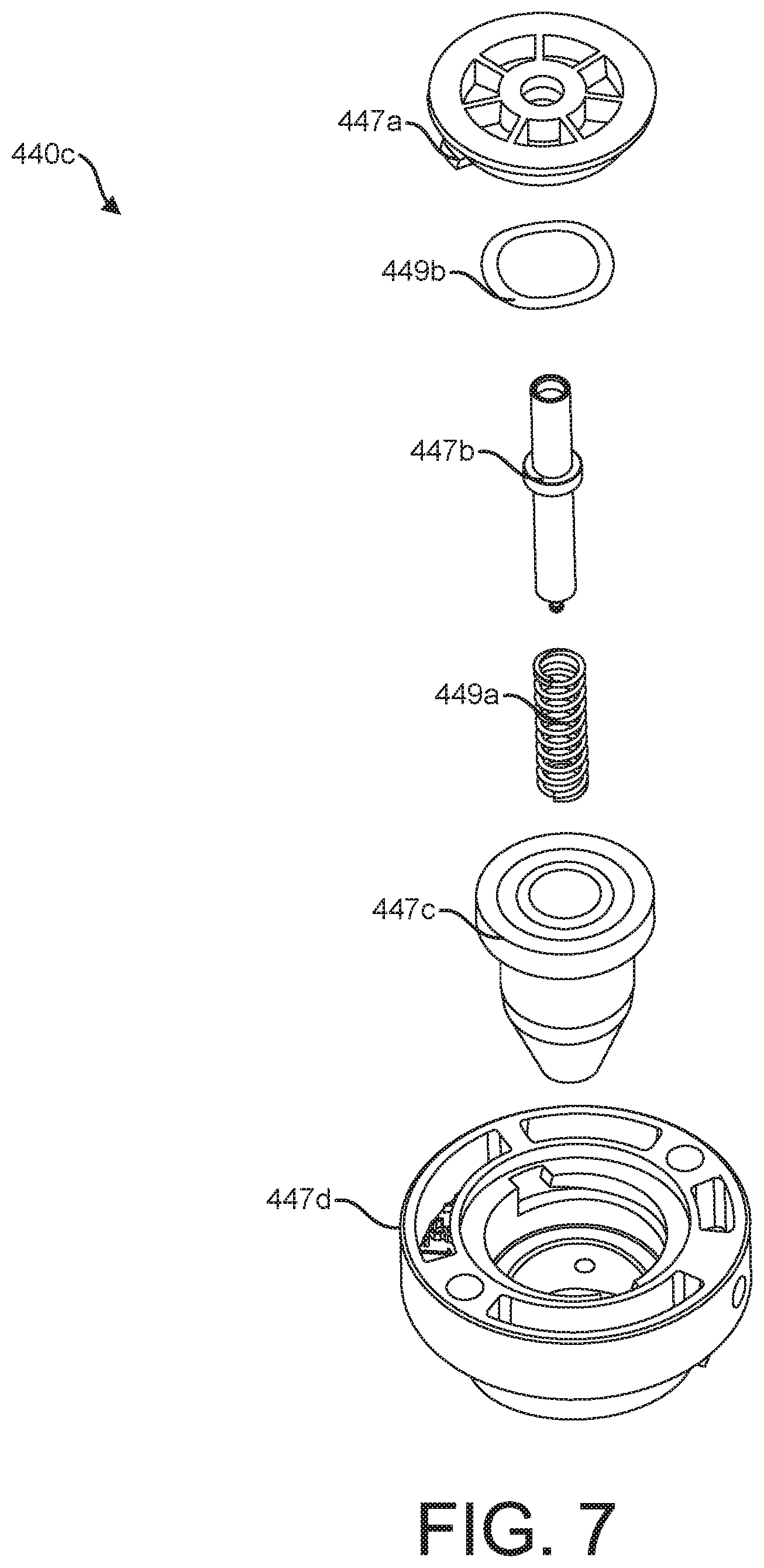
[0031] FIG. 7 is an exploded view of a charge feedthru of the charge assembly.
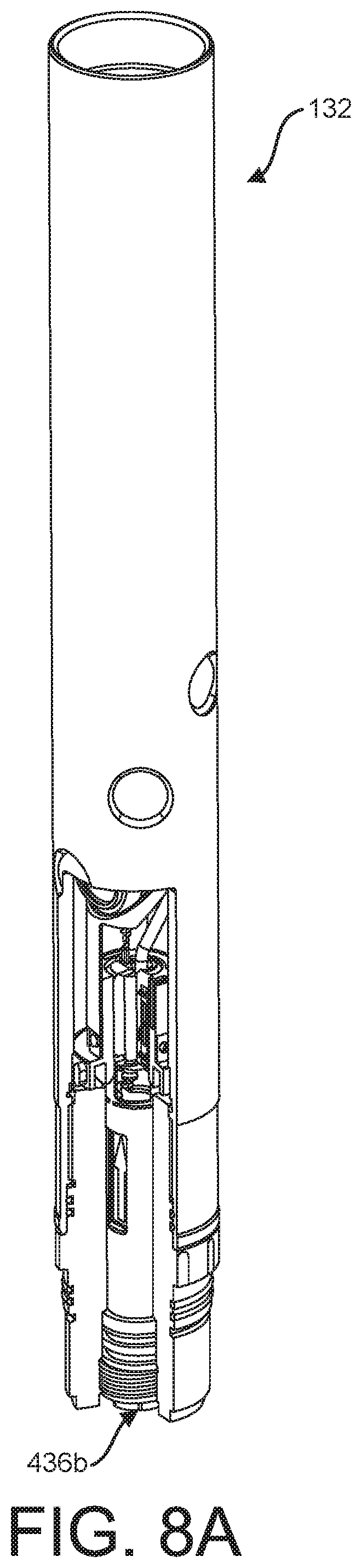
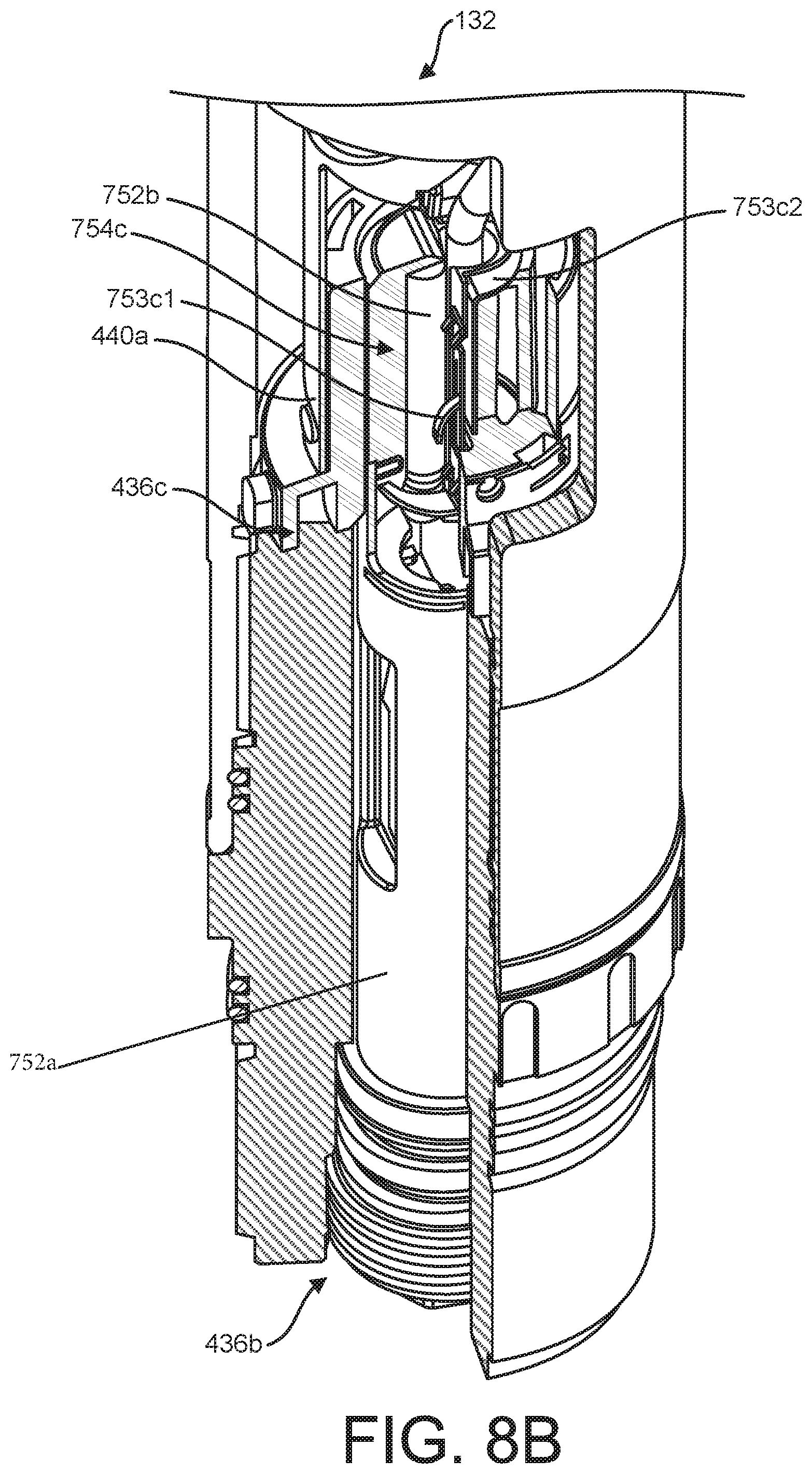
[0032] FIGS. 8A-8C are partial cross-sectional views of the perforating unit depicting a detonation assembly therein.
[0033] FIG. 9 is another partial cross-sectional view of a portion of the perforating unit and the detonator assembly therein.
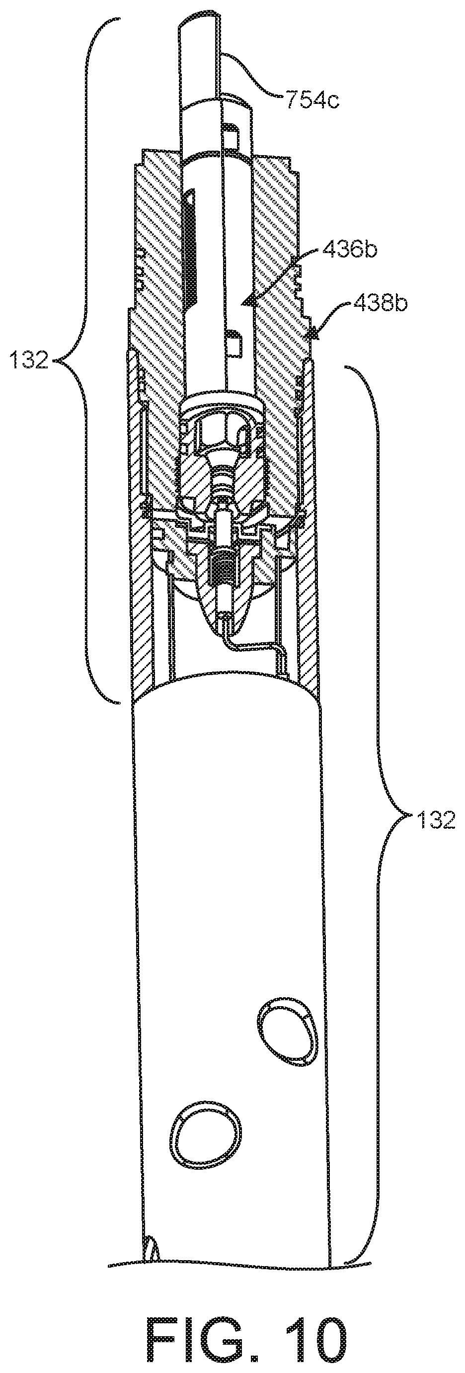
[0034] FIG. 10 is a partial cross-sectional view of a portion of the perforating unit connected to an adjacent perforating unit.
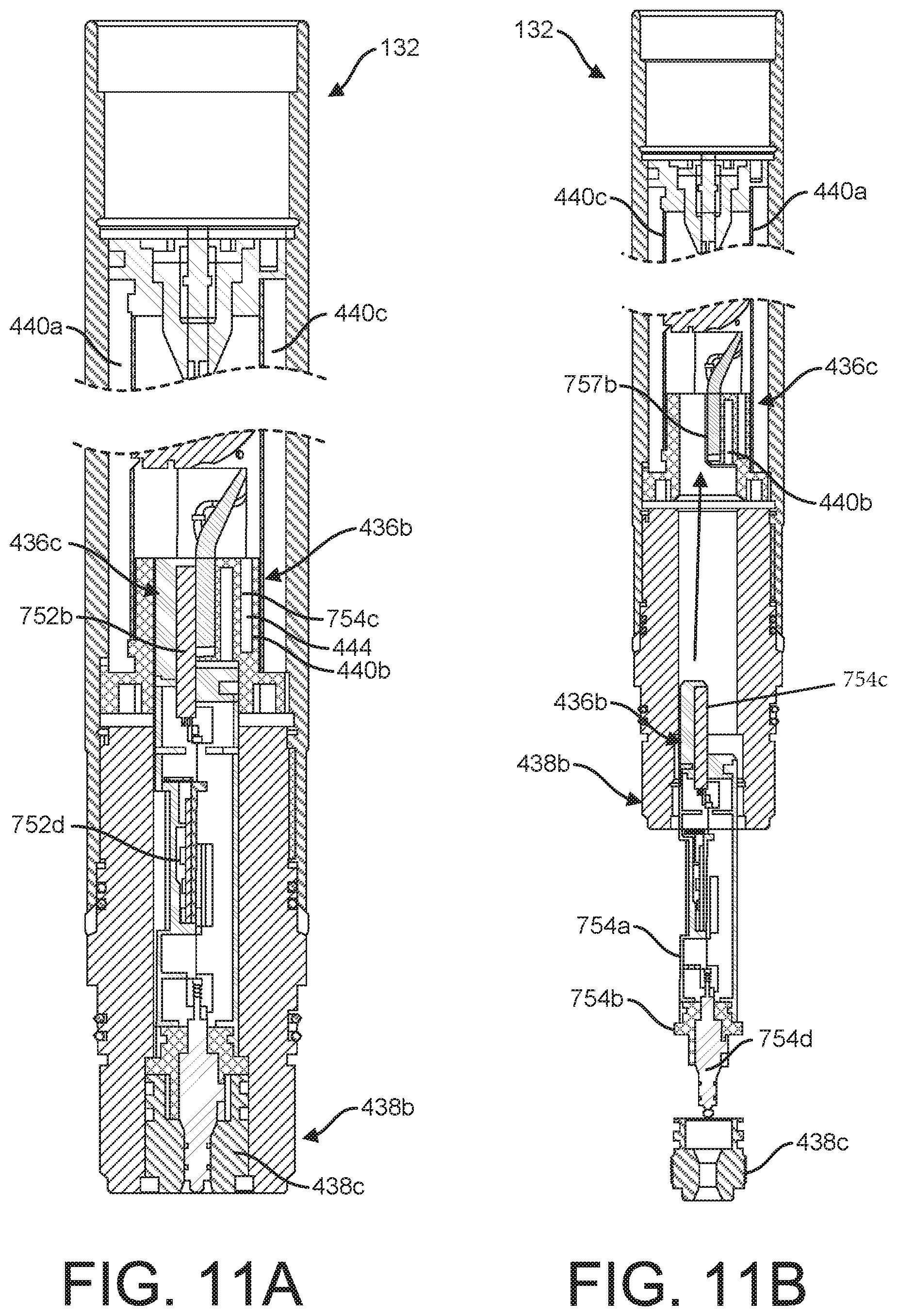
[0035] FIGS. 11A and 11B are longitudinal cross-sectional views of the detonator assembly in a seated and an unseated position, respectively, in the perforating unit.
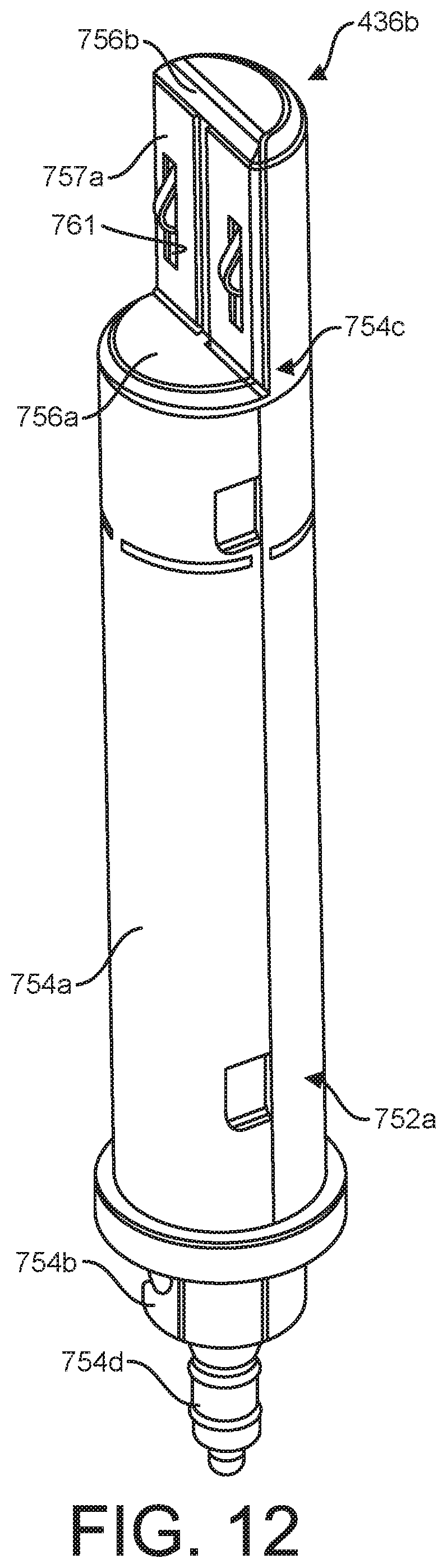
[0036] FIG. 12 is a perspective view of the detonator assembly.
[0037] FIGS. 13A-13B are exploded views of the detonator assembly.
[0038] FIG. 14 is an exploded view of a detonator contact and a corresponding charge contact.
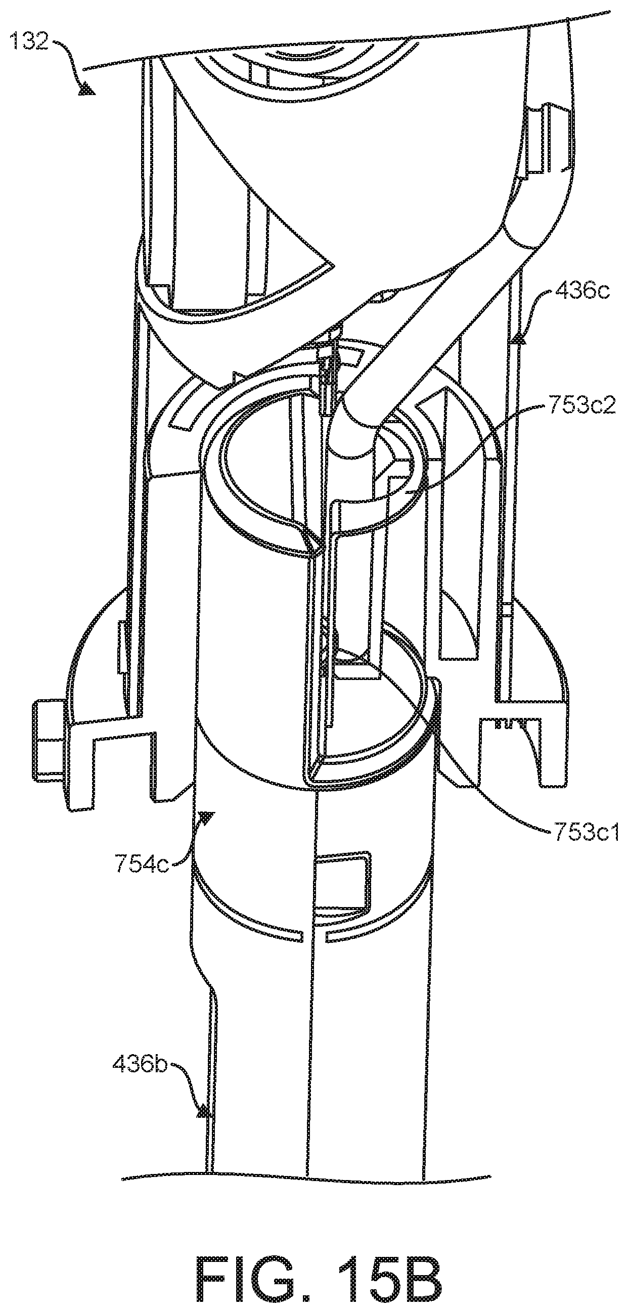
[0039] FIGS. 15A and 15B are partial cross-sectional views of the perforating unit with portions removed to show the detonator and charge contacts in a disengaged and an engaged position, respectively.
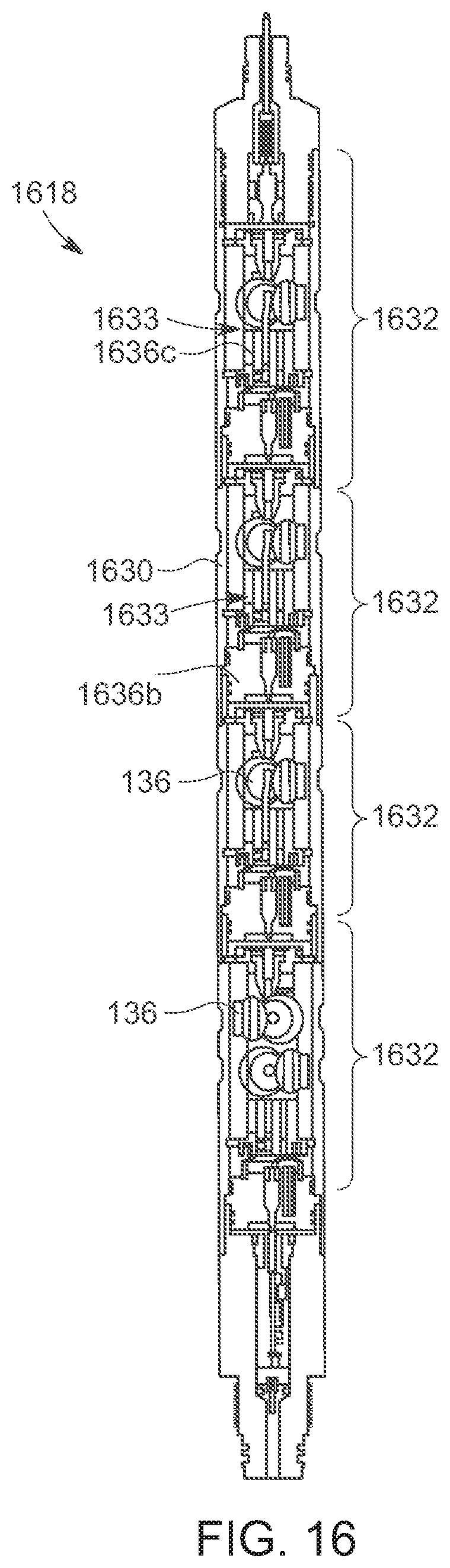
[0040] FIG. 16 is a longitudinal, cross-sectional view of a portion of a downhole perforating tool comprising perforating units, each perforating unit comprising an integrated detonation assembly, on one particular embodiment.
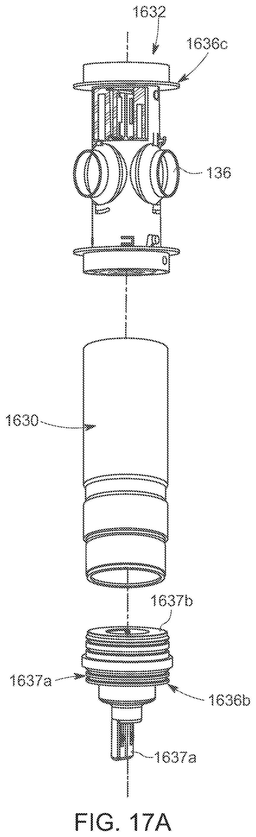
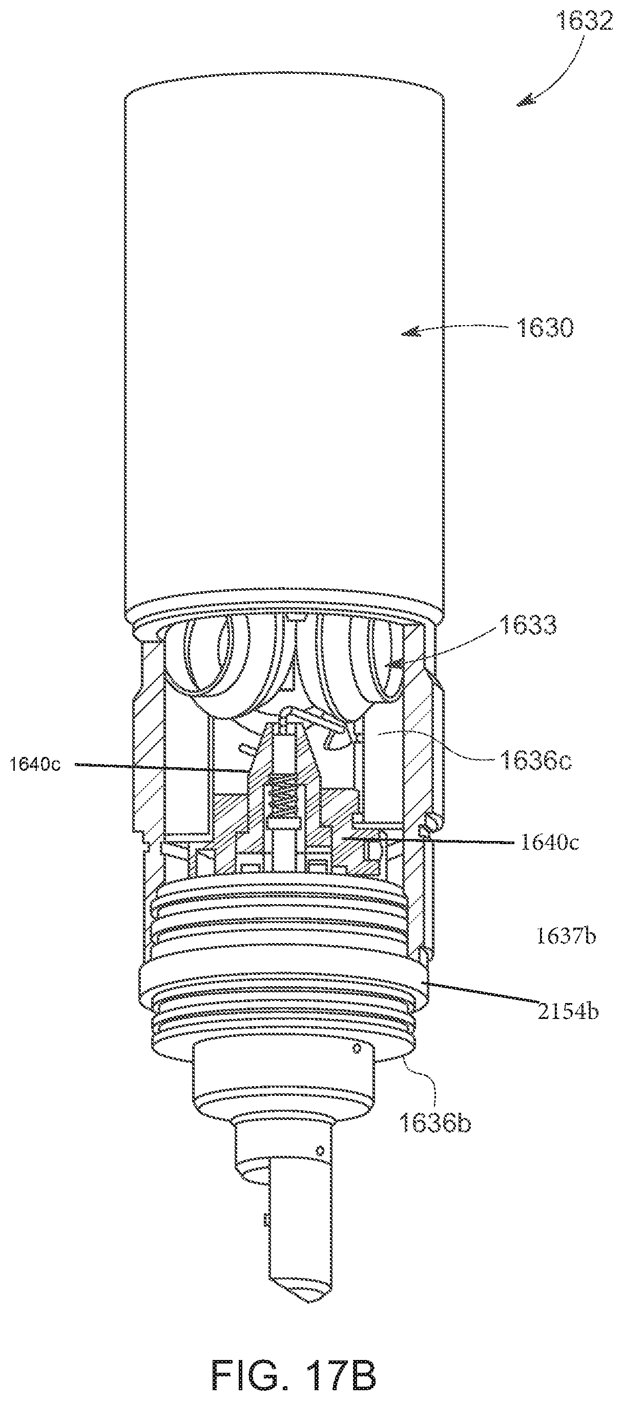
[0041] FIGS. 17A and 17B are exploded and perspective views of the perforating unit of FIG. 16.
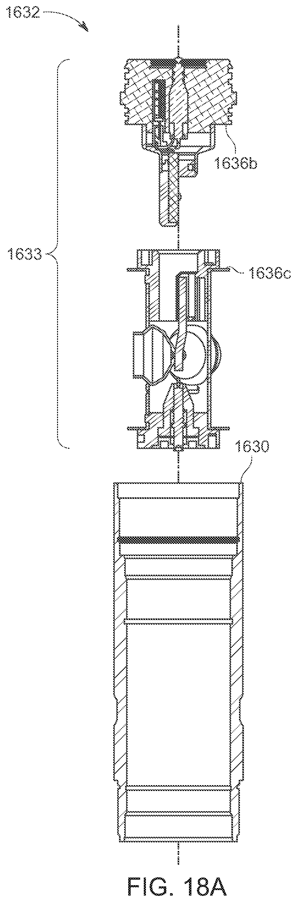
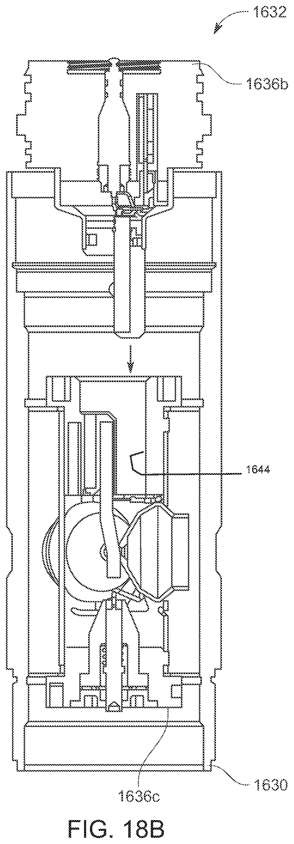
[0042] FIGS. 18A-18C are exploded, partially assembled, and longitudinal, cross-sectional views, respectively, of the perforating unit of FIG. 16.
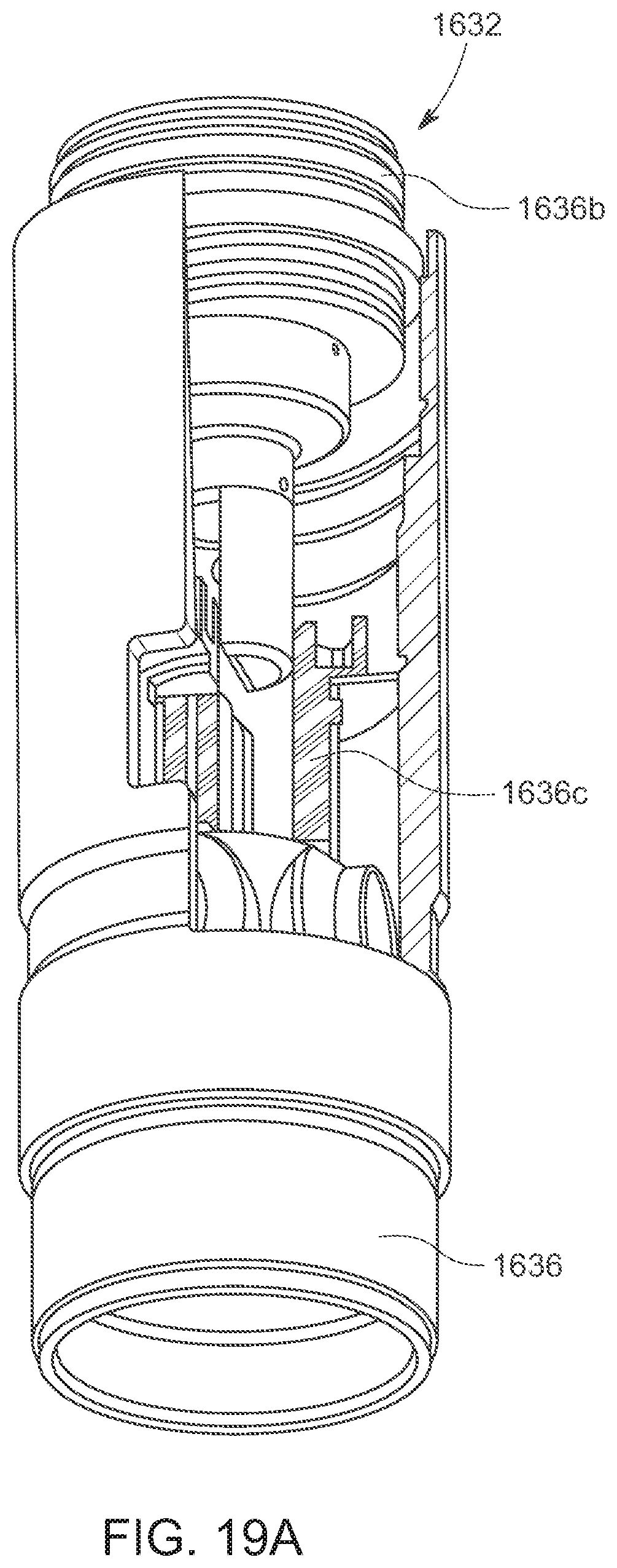
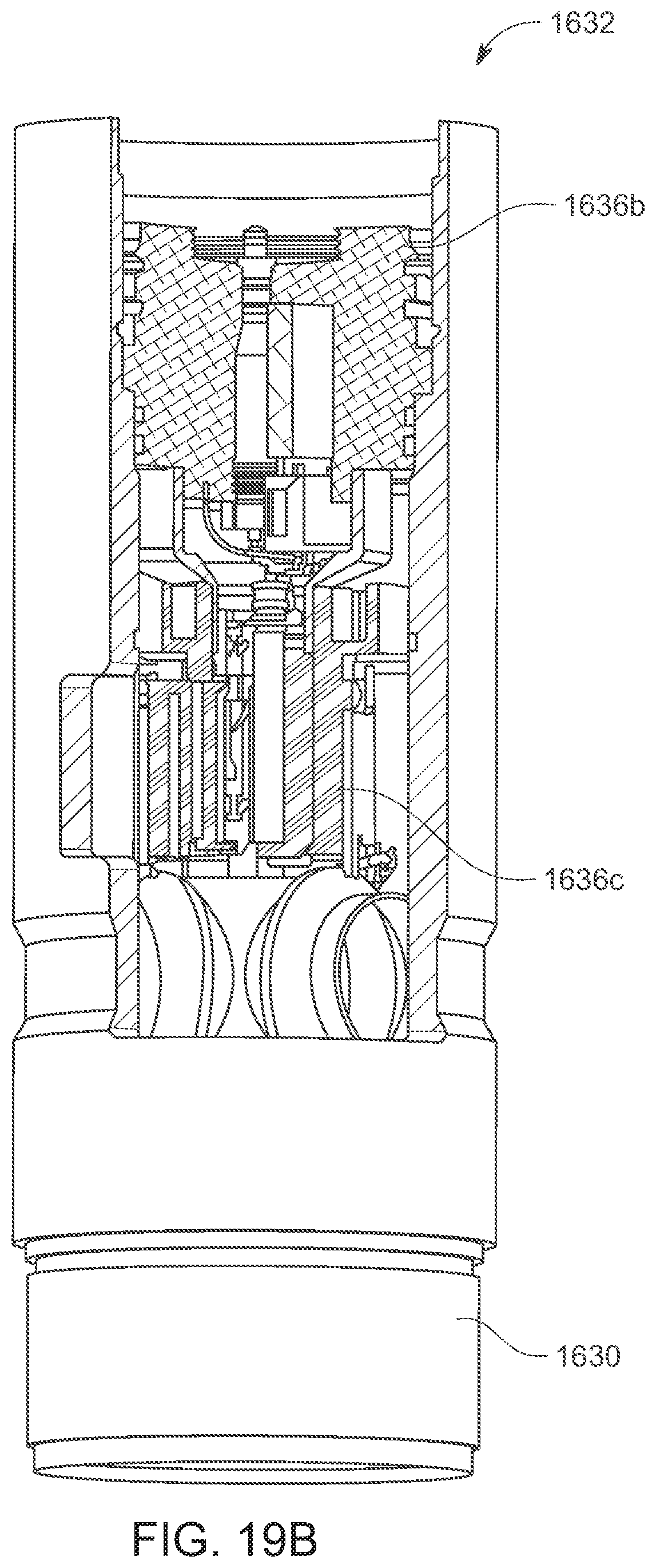
[0043] FIGS. 19A-19C are various partial, cross-sectional views of the perforating unit of FIG. 16.
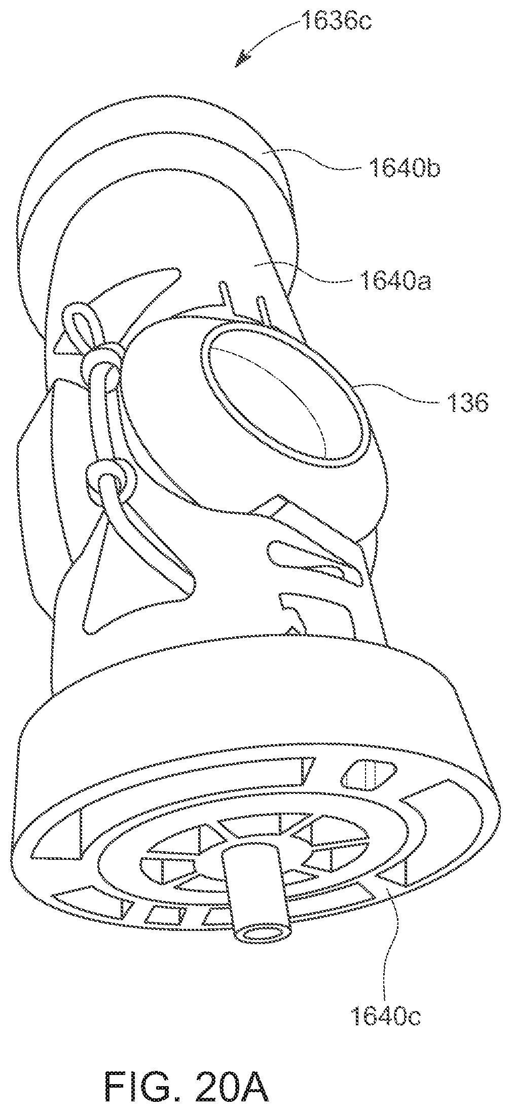
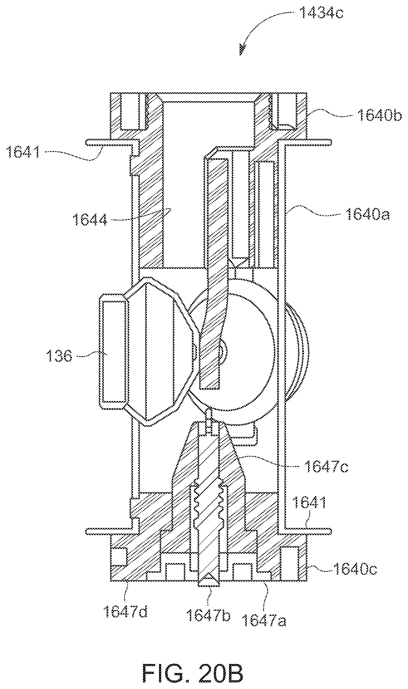
[0044] FIGS. 20A-20C are perspective, longitudinal cross-sectional, and exploded views, respectively, of a charge assembly of the perforating unit of FIG. 16.
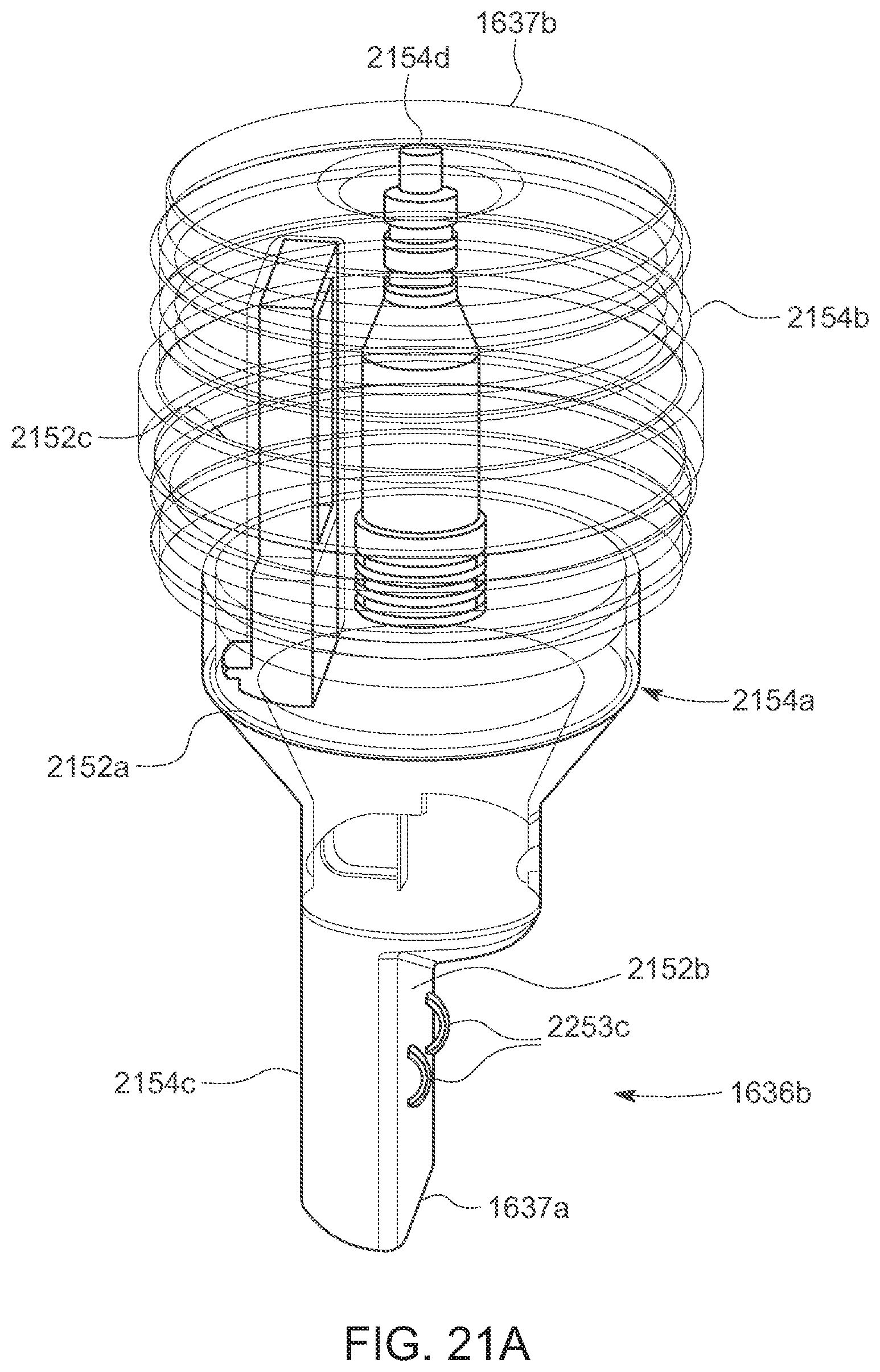
[0045] FIGS. 21A-21C are hidden line, perspective view, and end views, respectively, of a detonator assembly of the perforating unit of FIG. 16.
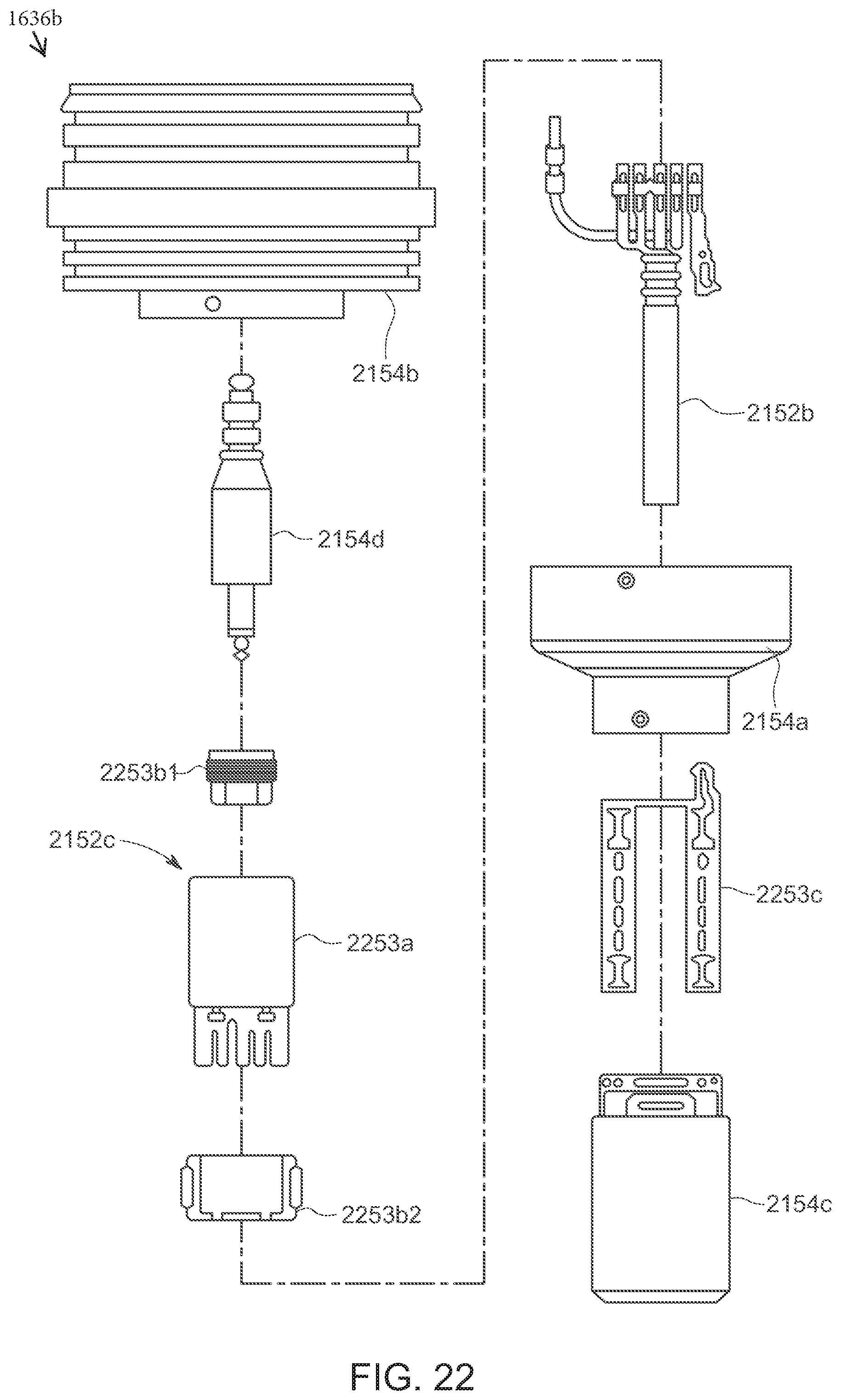
[0046] FIG. 22 is an exploded view of the detonator assembly.
[0047] FIG. 23 is a flow chart depicting a method of assembling a downhole perforating tool.
DETAILED DESCRIPTION
[0048] The description that follows includes exemplary apparatus, methods, techniques, and/or instruction sequences that embody techniques of the present subject matter. However, it is understood that the described embodiments may be practiced without these specific details.
[0049] This disclosure relates to a denotation assembly of a downhole perforating tool positionable in a wellbore at a wellsite. The perforating tool is provided with one or more perforating units, each perforating unit including an outer housing and a detonation assembly. The detonation assembly includes a charge assembly and a detonator assembly secured in the outer housing. The perforating units have quick-locking features to facilitate assembly and operation of the perforating tool and its detonator.
[0050] The charge and detonator assemblies are provided with quick-locking features for quick, one-way, redundant, and secure assembly and operation. For example, the charge and detonator assemblies may have one-way pin and guide (e.g., slot) locking mechanisms (with or without additional locks) for securing the components in place. In another example, the charge and detonator assemblies may have components shaped for one-way insertion into and/or connection with adjacent components to assure proper positioning and fit of the components.
[0051] In yet another example, the charge and detonator assemblies may have locking contacts with push-in place dual spring activation and redundant contact surfaces for maintaining a communication connection with the detonator and/or between the detonator assembly and the charge assembly for the passage of signals therebetween. The communication links and/or connections may be or include various communication components, such as wires, cables, plates, contacts, switches, plugs, and/or other features, capable of passing electrical, power, and/or other signals.
[0052] The present disclosure seeks to provide features capable of providing one or more of the following, among others: means for signal communication (e.g., electrical connection), push in place assembly, spring loaded contact, redundant components and/or contacts, mechanisms to assure good electrical contact, reliable communication and/or operation, pre-assembly and/or offsite assembly capabilities, snap on electrical connections, quick connections and/or locks, no requirement for soldering and/or crimping contacts, reliability, time savings, low maintenance costs, etc.
[0053] FIG. 1 is a schematic diagram depicting a wellsite 100 with surface equipment 102a and downhole equipment 102b positioned in a wellbore 104. The downhole equipment 102b comprises a downhole tool 118 with a perforating unit 132 having a quick-locking detonator assembly 133 or an integrated detonation assembly 1633 as is described further. The downhole tool 118 may be any downhole tool usable in the wellbore 104. When in combination with the perforating unit 132, the downhole tool 118 is referred to as a downhole perforating tool.
[0054] The wellsite 100 may be any wellsite positioned about a subterranean formation, such as an unconventional formation (e.g., shale) with a reservoir (e.g., oil, gas, water) therein. The surface equipment 102a includes a crane 106, a truck 108, a wellhead assembly 110, and a surface unit 111. The crane 106 supports a pulley 112. The truck 108 supports a spool 114. A conveyance (e.g., wireline) 116 extends from the spool 114 over the pulley 112 and into the wellbore 104. The surface unit 111 is coupled to the conveyance 116 for communication therewith.
[0055] The wellhead assembly 110 is disposed at a surface opening of the wellbore 104. An example wellhead assembly 110 is shown in FIG. 2. The wellhead assembly 110 includes a wireline lubricator 220a, a hydraulic disconnect 220b, a frac tree 220c, and a wellhead 220d. Portions of the wellhead assembly 110 are connectable to pressure control equipment (not shown) for the passage of fluids and/or to control pressures at the wellsite 100. A passage 119a extends through the wireline lubricator 220a, the hydraulic disconnect 220b, the frac tree 220c, and the wellhead 220d for fluid communication with the wellbore 104. Valves 119b are positioned about the wellhead assembly 110 to controllably restrict passage of fluid through portions thereof.
[0056] The wireline lubricator 220a is positioned at an upper end of the wellhead assembly 110 and is receivably supported in the hydraulic disconnect 220b. Seals 222 are positioned at an upper end of the wireline lubricator 220a for fluid isolation within the wellhead assembly 110. The wireline lubricator 220a may be detached from the wellhead assembly 110 and carried by the crane 106 for placement in the hydraulic disconnect 220b.
[0057] The hydraulic disconnect 220b includes a tulip 226 at an upper end to receive the wireline lubricator 220a. The hydraulic disconnect 220b is supported between the wireline lubricator 220a and the frac tree 220c. Once the wireline lubricator 220a is positioned in the tulip 226, the valves 119b on the hydraulic disconnect 220b may be opened to pass fluid therethrough or closed to isolate the passage therein. A lower end of hydraulic disconnect 220b is connectable to an upper end of the frac tree 220c. The frac tree 220c includes a goat head 228a and a cross member 228b. A lower end of the frac tree 220c is connectable to the wellhead 220d.
[0058] Referring back to FIG. 1, the downhole equipment 102b includes a casing 117 positioned in the wellbore 104 and the downhole tool 118 supported in the wellbore 104 by the conveyance 116. The casing 117 is a tubular member that lines the wellbore 104 and is connected to the wellhead 220d. Note that in some embodiments the casing 117 may be omitted (e.g., for openhole applications), or the casing 117 may be installed in only a portion of the wellbore 104.
[0059] The downhole tool 118 may be a downhole perforating tool or other downhole tool disposable in the wellbore 104 capable of carrying a perforating unit 132 for perforating the wellbore 104 as is described further herein.
Quick Locking Detonator Assembly
[0060] FIGS. 3-15 depict aspects of the quick locking detonation assembly 133 usable with the perforating units 132 of FIG. 1. Referring to FIGS. 1 and 3, the downhole tool 118 comprises a housing 130 with a series of the perforating units 132 therein. The housing 130 is a tubular member positionable in the wellbore 104 by the conveyance 116, and is shaped to receivably support each of the perforating units 132 therein. The perforating units 132 are connected together end to end in series. Threaded connections may be provided at each end of the perforating units 132 for connecting one or more perforating units 132 together. In the illustrated embodiment, there are four perforating units 132, but other embodiments may employ different numbers of perforating units 132. Some embodiments may use as few as one perforating unit 132.
[0061] The perforating units 132 are positioned in the housing 130 and carry the detonation assembly 133. The detonation assembly 133 carries shaped charges 136. The shaped charges 136 are explosive components that form a focused radially-oriented jet when activated. This jet makes a perforation 135 that extends through the wall of the wellbore 104 (and the casing 117 and cement if present) and into the subterranean formation surrounding the wellbore 104. The shaped charges 136 may be configured to create the perforations 135 for passage of fracturing (or injection) fluid into the formation for hydraulic fracturing therein.
[0062] The perforating units 132 may be communicatively connected to the surface unit 111 by the wireline 116 and/or by other means (e.g., wireline, electromagnetic, sonar, or other communication means). The perforating units 132 may be independently operated, or communicatively linked together for integrated operation therebetween. A communication link (e.g., wire or cable, not separately shown) may extend from the wireline 116 through the housing 130 and/or the perforating units 132. The perforating units 132 may be connected by the communication link for communication therebetween and/or for communication with the other components of the downhole tool 118.
[0063] The downhole tool 118 may be provided with various components, such as a conveyance connector 133a, a collar locator ("CCL") 133b, and a plug-setting tool 133c, all shown in FIG. 1. The conveyance connector 133a may be provided at a first end of the downhole tool 118 for connection to the wireline 116. The plug setting tool 133c may secure the downhole tool 118 at specified depths along the wellbore 104.
[0064] The downhole tool 118 and/or one or more of the perforating units 132 may be coupled via a wired or wireless connection to the surface unit 111 as described above for operation therewith. The perforating unit(s) 132 may be activated by the surface unit 111 to selectively fire one or more of the shaped charges 136 to form the perforations 135 as schematically depicted in FIG. 1.
[0065] During operation, the downhole tool 118 may be carried in the wireline lubricator 220a via the wireline 116 to the wellsite 100 with the crane 106. Once the wireline lubricator 220a is secured in the tulip 226, the valve 119b of the hydraulic disconnect 220b may be opened to pump fluid to push the downhole tool 118 through the wellhead assembly 110 and into the wellbore 104. Fluid beneath the downhole tool 118 may be pumped back to the surface or exited out the wellbore 104 via pre-existing perforations (not shown) in the casing 118 to avoid the need for the fluid to return to the surface.
[0066] The CCL 133b may communicate an electrical signal up the wireline 116 to the surface unit 111 as it passes between adjacent segments of the casing 117. A position of the downhole tool 118 may be determined by counting these signals as the perforating system is pumped down the wellbore and by knowing the length of each segment of casing 117. However, other embodiments may use other techniques for determining the location of the CCL 133b in the wellbore 104.
[0067] When the bottom (i.e. downhole end) of the downhole tool 118 is at a desired position above the perforations 135 that are closest to the surface, pumping may be terminated. A coded communication signal may be sent down the wireline 116 to activate the plug-setting tool 133c to lock the downhole tool 118 in position. The signal may also be used to activate a switch in the perforating unit 132 to activate the perforating unit 132 to fire as is described further herein. Once fired, the plug-setting tool 133c may be activated to disconnect the downhole tool 118 and move the perforating tool 118 to another location, or out of the wellbore 104.
[0068] FIGS. 4A-5 show one of the perforating units 132 in greater detail. FIGS. 4A and 4B show perspective and longitudinal, cross-sectional views of the perforating unit 132. FIG. 5 shows a cross-sectional, exploded view of the perforating unit 132. As shown in these views, the perforating unit 132 includes a perforating housing 436a, and the detonation assembly 133. The detonation assembly 133 includes a detonator assembly 436b, and a charge assembly 436c.
[0069] The perforating housing 436a includes an outer tube 438a, a support sub 438b, and a retainer 438c. The outer tube 438a is a tubular member slidingly receivable in the housing 130 (shown in FIG. 3). The outer tube 438a is shaped to receive the charge assembly 436c therein. The outer tube 438a has an end shaped to receive the support sub 438b and an opposite end shaped for connection to another perforating unit 132. The support sub 438b has an end insertable into the opposite end of the outer tube 438a and threadedly connected therewith. The support sub 438b also has another end extending from the outer tube 438a for connection to an adjacent perforating unit 132.
[0070] The support sub 438b is a tubular member shaped to support the retainer 438c and the detonator assembly 436b. The retainer 438c is positioned in an end of the support sub 438b to secure the detonator assembly 436b in the perforator housing 436a. The detonator assembly 436b is positioned in the support sub 438b and extends from the retainer 438c a distance into the charge assembly 436c for operative connection therewith as is described further herein.
[0071] Each of the perforating units 132 is provided with a communication link (e.g., wire) 441 extending therethrough for activating the detonator assembly 436b to fire the shaped charges 136. The communication link 441 may be a wire extending from the detonator assembly 436b through the charge tube 440a and to the charge feedthru 440c. The perforating units 132, where multiple perforating units 132 are employed, are connected in series with the communication link 441 coupled therebetween for selective activation of one or more of the perforating units 132. The communication link 441 of each perforating unit 132 may be coupled to an adjacent perforating unit 132 at each end of the perforation unit via the detonator assembly 436b at one end and the charge feedthru 440c at the other end for communication therewith. This connection may be repeated between the perforating units 132 to provide a series of connections for communication across the perforating units 132.
[0072] Referring to FIGS. 6A-6B, and 7 (as well as FIGS. 4B-5), features of the charge assembly 436c are shown. FIGS. 6A and 6B are exploded and partial cross-sectional views, respectively, of a charge assembly 436c of the perforating unit 132. FIG. 7 is an exploded view of a charge feedthru 440c of the charge assembly 436c.
[0073] The charge assembly 436c includes a charge tube 440a, a receiver 440b at one end of the charge tube 440a, and the charge feedthru 440c at an opposite end of the charge tube 440a. The charge tube 440a is slidingly receivable in the outer tube 438a. The charge tube 440a has the shaped charges 136 supported therein. The charge tube 440a also has a charge cable 442a and ports 442b.
[0074] The receiver 440b may be a flange shaped member receivable about an end of the charge tube 440a for connection to the support sub 438b. The receiver 440b may also be provided with a charge receptacle 444 shaped to receive the end of the detonator assembly 436b for connection therewith. The charge cable (or detonator cord) 442a is a fuse connected to the receiver 440b. The charge cable 442a extends from the receptacle 444 through the charge tube 440a and along a periphery of the charge tube 440a in a spiral configuration.
[0075] The charge cable 442a is connected to each of the shaped charges 136 in the charge tube 440a for activation thereof. The ports 442b extend through the charge tube 440a. The shaped charges 136 are positioned about the ports 442b to fire jets therethrough upon detonation. The ports 442b may be alignable with openings 443 in the perforating housing 436a for firing therethrough upon detonation.
[0076] The charge feedthru 440c is positionable at an opposite end of the charge tube 440a from the receiver 440b. As shown in greater detail in FIG. 7, the feedthru 440c includes a locking cap (or plate) 447a, plunger 447b, retainer 447c, and end plate 447d. The end plate 447d is seated on the locking cap 447a. The plunger 447b is supported on the locking cap 447a and extends through the end plate 447d. The plunger 447b is supported on the locking cap 447a and extends through the retainer 447c. Springs 449a,b may optionally be provided to support the plunger 447b in the retainer 447c.
[0077] As shown in FIGS. 4B and 6A, the charge tube 440a, the receiver 440b, and the feedthru 440c may have quick-locking features for lockingly connection in a desired position. In the example shown, the charge tube 440a is provided with guide slots 446a,b at each end shaped to matingly receive keys 448a,b positioned on the receiver 440b and the feedthru 440c, respectively.
[0078] When inserted into the end of the charge tube 440a, the key 448a of the receiver 440b is slidingly receivable into the guide slot 446a. The receiver 440b may be rotated so that the key 448a passes into the guide slot 446a, thereby positioning the receiver 440b in the desired position while also preventing unintentional retraction of the receiver 440b out of the charge tube 440a.
[0079] The charge tube 440a may also be provided with a locking tabs 451a and fastener holes 451b to secure the receiver 440b and feedthru 440c in position. The locking tabs 451a may be a cutout portion of the charge tube 440a corresponding to tab cavity 450a in the receiver 440b and the feedthru 440c. When the receiver 440b/the feedthru 440c are in position, the corresponding locking tab 451a may be pressed into the tab cavity 450a thereby further preventing movement of the receiver 440b/feedthru tube 440c about the charge tube 440a. Fasteners (not shown), such as pins, screws, bolts, etc., may be passed through fastener hole 451b and into a mated hole 450b in the receiver 440b/feedthru tube 440c to secure the receiver 440b/feedthru 440c to the charge tube 440a.
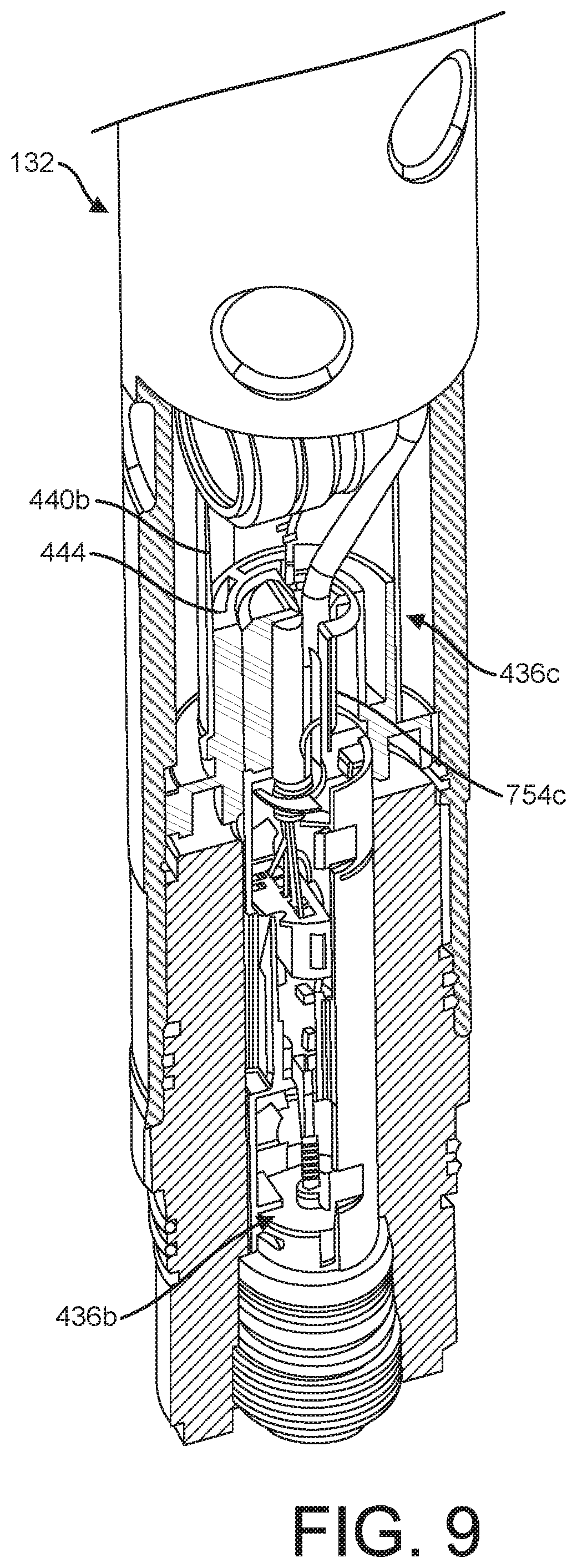
[0080] As also shown in FIGS. 4B and 6A and in FIGS. 8A-9, the receiver 440b is shaped to matingly receive the detonator assembly 436b. FIGS. 8A-8C are partial cross-sectional views of the perforating unit 132 depicting a detonation assembly 133 therein. FIG. 9 is another partial cross-sectional view of a portion of the perforating unit 132 and the detonator assembly 133 therein.
[0081] As shown in these views, the detonator assembly 436b is insertable into the support sub 438b and into the end of the charge assembly 436c. The receptacle 444 of the receiver may be an offset (e.g., hemispherical) insert placed along an inner surface of the receiver 440b with features corresponding with the end of the detonator assembly 436b. The receptacle 444 may have, for example, a shape, surfaces, contacts, etc., for receivingly engaging the detonator assembly 436 to provide a secure fit for contact and communication therebetween as is described further herein.
[0082] FIGS. 10 and 11A-13B show various views of the perforating unit 132 and the detonator assembly 436b. FIG. 10 is a partial cross-sectional view of the perforating unit 132 and the detonator assembly 436b therein. FIGS. 11A and 11B show cross-sectional views of the detonator assembly 436b in a seated and an unseated position, respectively. FIGS. 12, 13A, and 13B show the detonator assembly 436b outside of the perforating unit 132.
[0083] As shown in these views, the detonator assembly 436b includes a detonator housing 752a, a detonator 752b, and a switch assembly (or trigger) 752d. The detonator assembly 436b also includes a tube portions 754a, a bulkhead 754b, a second connector 754c, and a detonator feedthru 754d. The detonator housing 752a is slidably positionable in the support sub 438b. The detonator housing 752a may include one or more tube portions 754a connectable to form an enclosed chamber 759. The bulkhead 754b and the second connector 754c are positioned at opposite ends of the detonator housing 752a to close each end thereof.
[0084] The bulkhead 754b is positionable between the detonator housing 752a and the retainer 438c. A portion of the bulkhead 754b is insertable into and threadedly connected to an end of the detonator housing 752a. Another portion of the bulkhead 754b extends from the detonator housing 752a and is insertable into and threadedly connectable to the retainer 438c. The bulkhead 754b has a passage to receive the detonator feedthru 754d therethrough. The bulkhead 754b supports the detonator feedthru 754d about the end of the detonator assembly 436b to form a first connector for connection to the charge assembly 436c of an adjacent perforating unit 132.
[0085] The detonator feedthru 754d is connected by the switch assembly 752d to the detonator 752b. The switch assembly 752d includes a switch 753a, a plug 753b, and contact 753c1. The switch assembly 752d also includes connectors 755a1-a5 and cables 755b. The plug 753b is seated in the switch 753a. The connectors 755a1-a4 are connected to the switch plug 753b via cables 755b. The connectors 755a1-a3 are also connected to the detonator feedthru 754d, bulkhead 754b, contact 753c1, respectively. The connector 755a4 is also connected the switch plug 753b to the detonator 752b. The connectors 755a1-a4 may take various forms. In the examples shown, the connectors 755a1-a3 include a pin contact 755a1, a spring coupling 755a2, and a slotted receptacle 755a3 capable of mating with the components and connectable with the cables 755b for communication therebetween. The cables 755b are provided with connectors 755a5 for insertion into the switch plug 753b.
[0086] As shown in FIGS. 8A-8C, 9A-9B, and 11A-11B, the second connector 754c is positioned between the detonator housing 752a and the charge tube 440a. The second connector 754c has a cylindrical portion 756a positioned in an end of the detonator housing 752a and an insert (e.g., hemispherical) portion 756b extending from an end of the detonator housing 752a. The insert portion 756b extends from the detonator housing 752a and is positionable into the charge tube 440a for communicative coupling with the receptacle 444 of the receiver 440b.
[0087] The cylindrical portion 756a is shaped to close an end of the detonator housing 752a. The hemispherical portion 756b is insertable through the support sub 438b and into the receiver 440b. The hemispherical portion 756b is shaped to matingly engage the contact receiver positioned in the charge tube 440a. The hemispherical portion 756b is also shaped for a one way fit into the charge tube 440a for positive alignment therein. The hemispherical portion 756b is also provided with a contact surface 757a positionable against a corresponding contact surface 757b of the receptacle 444.
[0088] The contacts 753c1,c2 are shown in greater detail in FIG. 14. The detonation contacts 753c1,c2 may include a contact portion 760a and a support portion 760b. Both support portions 760b have a curved portion shaped to receivingly engage an outer surface of the detonator 752b, with the flat contact portions 760a extending from the curved support portions 760b. The contact portions 760a of each of the contacts 753c1,c2 includes a pair of arms 762a,b positionable parallel to each other.
[0089] Each of the arms 762a have elongate cutout portions that are curved about the flat portion. The cutout portions include a curved portion 764a and tip portions 764b. The curved portions 764a are attached at one end from the flat portion and extend therefrom to rise a distance above the flat portion. The tip portions 764b extend from the curved portions through an opening defined by cutout of the arms 762a, and to a distance below the flat portion.
[0090] The contacts 753c1,c2 may be of a conductive material (e.g., metal). The arms 762a may be compressible against the arms 762b of the adjacent support arms 762b. When the curved arms 762a are compressed against the arms 762b, the curved arms 762a have a spring force that extends therefrom. The curved arms 762a are shaped to extend through openings 761 in the second connector 754c.
[0091] The detonator contact 753c1 is connected at one end to the switch assembly 752d and has another end extended into the second connector 754c. The detonator 752b is supported in the housing between the switch assembly 752d and the second connector 754c. The detonator 752b is supported in the housing 752a by the contact 753c1. The curved portion 760b is shaped to receive an outer surface of the detonator 752b.
[0092] As shown in FIGS. 15A-15B (also seen in 8B-8C, 9-14B), a quick-locking connection is defined between the detonator assembly 436b and the charge assembly 436c. FIGS. 15A-15B show perforating unit 132 with the detonator assembly 436b before and after insertion into the charge assembly 436c. For descriptive purposes, portions of the perforating unit 132 have been removed so that engagement of the contacts 753c1, c2 may be seen.
[0093] When the second connector 754c is inserted into the receptacle 444 of the charge assembly 436c, the surface 757a of the second connector 754c is positioned adjacent the corresponding surface 757b of the receptacle 444. The curved arms 762a of the detonator contact 753c1 extends through the openings 761 for engagement with the charge receptacle 444. The spring force of the curved arms 762a urges the detonator contact 753c1 into communicative contact with the contact 753c2. The spring force may be defined to apply sufficient force to urge contact via the switch assembly 752d (FIGS. 13A-13B) to be maintained between the contacts 753c1 and 753c2.
[0094] In operation, a signal is sent from the surface unit 111 (shown in FIG. 1) via the wireline 116 and to the perforating units 132 (shown in FIG. 3). The signal passes through each of the perforation units 132 and to the detonator assemblies 436b (shown in FIG. 4B). When an electric communication signal from the surface unit 111 is passed through the downhole tool 118 by communication link 441, the signal is passed to a desired perforating unit 132. The signal identifies the detonator assembly 436b for a particular perforating unit 132. Once identified, the switch 753a opens enabling power to pass to the detonator 752b for that perforating unit 132.
[0095] The signal passes through the detonator feedthru 754d and the bulkhead 754b, and to the switch assembly 752d (shown in FIG. 13B). This signal opens the electric switch 753a, allowing electrical communication between a surface power supply and the detonator 752b. When the power at the surface applies voltage to the detonator 752b, the current is drawn and the detonator 752b causes the shaped charge to explode. The increased power supply voltage results in a current down the communication link 441. This current initiates a propellant within the shaped charge 136, which creates an expanding gas inside. This explosion activates the charge cable 442a which causes the shaped charges 136 in the charge tube (shown in FIG. 4B) to explode and creating the perforations 135 (shown in FIG. 1).
Integrated Detonation Assembly
[0096] FIGS. 16-22 depict aspects of the perforating units 1632 (with integrated detonator assemblies 1633) usable with the downhole tool 118 of FIGS. 1 and 2. As demonstrated in FIGS. 16-22, the perforating units 1632 may be configured with features to facilitate transport to, and assembly at, any location (e.g., an assembly facility, field locations, and/or a wellsite 100 of FIG. 1). Optionally, parts for the perforating units 1632 may be disposable, thereby eliminating the need to recover parts (and prepare them for reuse) and thereby providing fully disposable components after perforating.
[0097] The perforating units 1632 of FIGS. 16-23 may incorporate or be used in combination with features of the perforating units 132 of FIGS. 1-15. The perforating unit 1632 may have similar capabilities as the perforating units 132, and may also have additional capabilities including, but not limited to: transportability assembly at any location, reliable and faster connection, flexible configuration, ability to combine one or more integrated detonator assemblies and/or quick connected detonator assemblies within the downhole tool, automated electrical connection, electrical connection between multiple connected assemblies, disposable parts (i.e., no requirement to reuse parts), multiple contact electrical connectors, orientable connection and/or positioning (e.g., azimuthal orientation), mated connections, locked connections, among other.
[0098] FIG. 16 is a longitudinal, cross-sectional view of a portion of the downhole perforating tool 1618 comprising the perforating units 1632. Each of the perforating units 1632 comprise an integrated detonation assembly 1633. The perforating units 1632 are connected end to end in series. Each of the integrated detonation assemblies 1633 includes the detonator assembly 1636b and a charge assembly 1636c slidably insertable into an outer housing 1630. The integrated detonation assembly 1633 is configured for automatic connection (e.g., mechanical and electrical connection) during assembly as is described further herein.
[0099] FIGS. 17A-19C show features of one particular embodiment of the perforating units 1632 in greater detail. FIGS. 17A and 17B are exploded and perspective views of the perforating unit 1632 (partially in cross-section). FIGS. 18A-18C are exploded, partially assembled (partially in cross-section), and longitudinal, cross-sectional views, respectively, of the perforating unit 1632. FIGS. 19A-19C are various partial, cross-sectional views of the perforating unit 1632. This version of the perforating unit 1632 is similar to the perforating unit 132 of FIGS. 3-15, except this version has the integrated detonation assembly 1633. The integrated detonation assembly has mated interlocking components secured within the outer housing 1633 in a one-way azimuthal orientation for simplified assembly and reliable connection.
[0100] Referring collectively to FIGS. 17A-19C, the perforating unit 1632 may be assembled by inserting the detonator assembly 1636b and the charge assembly 1636c into the outer housing 1630. During this insertion, the detonator assembly 1636b and the charge assembly 1636c are positionable for one-way mated connection therebetween to form the integrated detonation assembly 1633. By this connection, the detonator assembly 1636b and the charge assembly 1636c are orientable within the outer housing 1630 and to each other for communicative connection therebetween.
[0101] The outer housing 1630 is a tubular member shaped to receive the integrated detonation assembly 1633 therein. The outer housing 1630 may be provided with connection means (e.g., internal threads) for connection of the outer housing 1630, and to a portion of an adjacent perforation unit 1632. While not shown in this version, additional housings may optionally be provided, such as the outer housing 130 and the outer tube 438a of FIGS. 2 and 5. Also, while not shown in FIGS. 16-22, the outer housing 1630 may be provided with openings 443, such as those of FIG. 4A for passing the shaped charges 136 therethrough.
[0102] The charge assembly 1636c is shown in greater detail in FIGS. 20A-20C. FIGS. 20A-20C are perspective, longitudinal cross-sectional, and exploded views, respectively, of a charge assembly 1636c of the perforating unit 1632. The charge assembly 1636c may be similar to the charge assembly 436c of FIGS. 6A-7. The charge assembly 1636c includes a charge tube 1640a, a receiver 1640b, a charge feedthru 1640c, and rings 1641.
[0103] The charge tube 1640a may be similar to the charge tube 440a of FIGS. 6A-6B. In this version, the charge tube 1640a is shown as a shorter tube with only three ports 1642b therethrough, and with three shaped charges 136 positioned thereabout. However, it will be appreciated that the size and number of ports 1642b may vary. The ports 1642b extend through the charge tube 1640a. The shaped charges 136 are positioned about the ports 1642b to fire jets therethrough upon detonation. The shaped charges 136 may be supported about the ports 1642 and held in place by bending a tab (not shown). The ports 1642b may be alignable with openings in the outer housing 1630 for firing therethrough upon detonation (see, e.g., openings 443 of FIG. 4A).
[0104] The receiver 1640b and the charge feedthru 1640c are insertable into and connected to opposite ends of the charge tube 1640a. One of the rings 1641 is positioned between the charge tube 1640a and the receiver 1640b, and the other ring 1641 is positioned between the charge tube 1640a and the receiver 1640b. The rings 1641 are supported about the charge tube 1640a adjacent to the receiver 1640b and the feedthru 1640, and are shaped for sliding insertion into the outer housing 1630 as shown in FIGS. 17A-17C. The rings 1641 may act as a centralizer shaped to support the charge assembly 1636c within the outer housing 1630.
[0105] As shown in FIG. 20C, the charge tube 1640a, the receiver 1640b, and the feedthru 1640c may have quick-locking features for locking connection and orientation therebetween. In the example shown, the charge tube 1640a is provided with guide slots 1646a,b at each end shaped to matingly receive keys 1648a,b positioned on the receiver 1640b and the feedthru 1640c, respectively. When inserted into the end of the charge tube 1640a, the key 1648a of the receiver 1640b is slidingly receivable into the guide slot 1646a. The receiver 1640b may be rotated so that the key 1648a passes into the guide slot 1646a, thereby positioning the receiver 1640b in the desired position while also helping to prevent unintentional retraction of the receiver 1640b out of the charge tube 1640a. The charge tube 1640a may also be provided with locking tabs 1651a, fastener holes 1651b for receiving the locking tabs 1651a, fasteners, and other locking features, such as those described in FIG. 7.
[0106] The charge tube 1640a also has a charge cable 1642a for communication with the shaped charges 136. The charge cable (or detonator cord) 1642a may act as a fuse connected to the receiver 1640b. The charge cable 1642a extends from the receiver 1640b through the charge tube 1640a and along an outer surface of the charge tube 1640a. The charge cable 1642a is connected to each of the shaped charges 136 in the charge tube 440a for activation thereof. The charge tube 1640a is supported within the outer housing 1630 between the two rings (end caps) 1641. The charge tube 1640a may be manufactured with clips (not shown) to support the charge cable 1642a (and wire 441 of FIG. 4) therethrough. The charge cable 1642 may be pushed into the receiver 1640b during assembly.
[0107] The receiver 1640b may have features similar to those of receiver 440b of FIGS. 6A-6B. The receiver 1640b may be a flange shaped member insertable into an end of the charge tube 1640a. The receiver 1640b may be shaped to receivingly support the ring 1641 adjacent to the charge tube 1640a. The receiver 1640b may also be provided with a charge receptacle 1644 therein shaped to receive a portion of the detonator assembly 1636b therein for connection and communication with the charge cable 1642.
[0108] The charge feedthru 1640c may be similar to the charge feedthru described in FIGS. 6A-7. The charge feedthru 1640c includes the locking cap 1647a, the plunger 1647b, the retainer 1647c, and the end plate 1647d similar to those described in FIG. 7. Optionally, the charge feedthru 1640c may also include springs. The charge feedthru 1640c may be inserted into and supported about the charge tube 1640a. The charge feedthru 1640c may also be shaped to receive the ring 1641 for support adjacent to the charge tube 1640a. The charge feedthru 1640c is shaped for engagement with the detonator assembly 1636b for connection and communication therewith. The locking cap 1647a may be secured (e.g., bolted to) the detonator assembly 1636b of an adjacent integrated detonation assembly 1633 to allow for the connection of a series of integrated detonation assemblies 1633. The plunger 1647b is communicatively connected to the detonator assembly 1636b of the adjacent integrated detonation assembly 1633 for communication therebetween.
[0109] When connected in series, multiple ones of the integrated detonation assemblies 1633 may be communicatively connected to pass signals therethrough for activation of the detonation assembly 1633 to set off the shaped charges 136 as is described further herein. A communication link (e.g., wire 441 of FIG. 4) may extend through the detonation assemblies 1633 of each of the perforating units 1632 (FIG. 16) for selectively activating one or more of the detonator assemblies 1636b to fire their respective shaped charges 136. Each integrated detonation assembly 1633 may be provided with connections at each end that are mated to facilitate connection to an adjacent detonation assembly 1633 and to reliably assure communicative connection therebetween or therethrough.
[0110] Referring collectively to FIGS. 18A-19C and 21B-21C, the detonator assembly 1636b is connectable to the outer housing 1633 and shaped for mating and communicative connection to the receiver 1640b and the charge feedthru 1640c. FIGS. 21A-22 show the detonator assembly 1236b in greater detail. FIGS. 21A-21C are hidden line, perspective view, and end views, respectively, of the detonator assembly 1636b of the perforating unit 1632. FIG. 22 is an exploded view of the detonator assembly 1636b.
[0111] As shown in these views, the detonator assembly 1636b includes a detonator housing 2154a, a bulkhead 2154b, a charge (second) connector 2154c, a detonator 2152b, a switch assembly (or trigger) 2152c, and a detonator feedthru 2154d. The detonator assembly 1636b may be assembled and oriented azimuthally to minimize mechanical shock during the electrical connection therebetween.
[0112] The bulkhead 2154b is at a charge end 1637b of the detonator housing 2152a and the charge connector 2154c is at the connection end 1637a of the detonator housing 2152a with the detonator housing 2152a therebetween. The detonator feedthru 2154d is supported in the bulkhead 2154b and the detonator 2152b is supported in the charge connector 2154c with the switch assembly 2152c connected therebetween. The bulkhead 2154b acts as a dual contact electrical connector on one side with the centralized detonator feedthru 2154d (which acts as an electrical pin) on the other. The bulkhead 2154b isolates the gun from pressure created when a shaped charge 136 in a perforating unit 1632 is fired, and maintains contact via the detonator feedthru 2154d.
[0113] The connection end 1637a of the charge connector 2154c is insertable into the outer housing 1630 and into the receiver 1640b positioned therein (see, e.g., FIG. 18B). The connection end 1637a of the charge connector 2154c may be shaped for mating insertion into the charge receptacle 1644 of the receiver 1646b in a similar manner as the second connector 754c of FIG. 12. Upon insertion, the connection end 1637a may be threadedly connected to the outer housing 1630. As shown in FIG. 17B, the charge end 1637b may be positioned adjacent the charge feedthru 1640c and threaded into the outer housing 1630 of an adjacent detonation assembly 1633, thereby connecting two adjacent detonation assemblies 1633. The charge end 1637b of the bulkhead 2154b is insertable into the outer housing 1630 for engagement with the charge feedthru 1640c. As shown in FIG. 21A, the bulkhead 2154b supports the detonator feedthru 2154d about the charge end 1637b of the detonator assembly 1636b for communicative connection to the plunger 1647b of the charge feedthru 1640c.
[0114] The detonator feedthru 2154d is connected by the switch assembly 2152c to the detonator 2152b. The switch assembly 2152c includes a switch 2253a, plugs 2253b1, b2, and contact 2253c. The plugs 2253b1,b2 are seated in the switch 2253a. The detonator 2152b is connected to the switch 2253a by connectors (not shown) for communication thereby, which may have features similar to those of in FIG. 21. At the connection end 1637a, the contacts 2253c extend through the charge connector 2154c for contact and communication with corresponding connectors (not shown) in the receiver 1646b. At the charge end 1637b, the detonator feedthru 2154d extends from the bulkhead 2154b for engagement with the plunger 1647b of the charge feedthru 1640c (FIG. 20B). The switch assembly 2152c connects the contacts 2253c and the detonator feedthru 2154d for communication therebetween.
[0115] In operation, a signal is sent from the surface unit 111 (shown in FIG. 1) via the wireline 116 and to the downhole (perforating) tool 118,1618 (see, FIGS. 3 and 16, respectively).
[0116] The signal passes through each of the perforation units 132,1632 and to the detonator assemblies 436b,1636b of FIGS. 2-15 and FIGS. 16-22, respectively. When an electric communication signal from the surface unit 111 is passed through the downhole tool 118,1618 by communication link 441, the signal is passed to a desired perforating unit 132, 1632. The signal identifies the detonator assembly 436b, 1636b for a particular perforating unit 132, 1632. Once identified, the switch assembly 752a, 2252a opens enabling power to pass to the detonator 752b, 2252b for that perforating unit 132, 1632.
[0117] The signal passes through the detonator feedthru 754d, 2154d and the bulkhead 754b, 2154b, and to the switch assembly 752d, 2152d (shown in FIG. 13B). This signal opens the electric switch 753a, 2253a, allowing electrical communication between a surface power supply and the detonator 752b, 2152b. When the power at the surface applies voltage to the detonator 752b, 2152b, the current is drawn and the detonator 752b, 2152b causes the shaped charge 136 to explode. The increased power supply voltage results in a current down the communication link 441. This current initiates a propellant within the shaped charge 136, which creates an expanding gas inside. This explosion activates the charge cable 442a, 1642a which causes the shaped charges 136 in the charge tube (shown in FIG. 4B, 16) to explode and creating the perforations 135 (shown in FIG. 1).
[0118] FIG. 23 is a flow chart depicting a method 2300 of assembling a downhole perforating tool, such as those described herein. The method 2300 involves 2380 assembling a detonator assembly; 2382 assembling a charge assembly; 2384 positioning the charge assembly in a tool housing; 2386 positioning the detonator assembly in the tool housing; and 2388 electrically connecting the detonator assembly with the charge assembly.
[0119] The method 2300 may involve assembling the detonation assembly by: connecting the bulkhead of the detonator assembly to the outer housing, and connecting the detonator assembly to the charge assembly by inserting the charge assembly in the outer housing while receiving the connection end of the charge connector into the receiver; and then connecting the outer housing to the downhole tool.
[0120] Part or all of the assembly may be performed on or offsite from the wellsite.
[0121] Portions of the method may be performed in various orders, and part or all may be repeated.
[0122] While the embodiments are described with reference to various implementations and exploitations, it will be understood that these embodiments are illustrative and that the scope of the inventive subject matter is not limited to them. Many variations, modifications, additions and improvements are possible. For example, various combinations of one or more of the features and/or methods provided herein may be used.
[0123] Plural instances may be provided for components, operations or structures described herein as a single instance. In general, structures and functionality presented as separate components in the exemplary configurations may be implemented as a combined structure or component. Similarly, structures and functionality presented as a single component may be implemented as separate components. These and other variations, modifications, additions, and improvements may fall within the scope of the inventive subject matter. For example, while certain connectors are provided herein, it will be appreciated that various forms of connection may be provided. While the figures herein depict a specific configuration or orientation, these may vary. First and second are not intended to limit the number or order.
[0124] Insofar as the description above and the accompanying drawings disclose any additional subject matter that is not within the scope of the claim(s) herein, the inventions are not dedicated to the public and the right to file one or more applications to claim such additional invention is reserved. Although a very narrow claim may be presented herein, it should be recognized the scope of this invention is much broader than presented by the claim(s). Broader claims may be submitted in an application that claims the benefit of priority from this application.
* * * * *
D00000
D00001
D00002
D00003
D00004
D00005
D00006
D00007
D00008
D00009
D00010
D00011
D00012
D00013
D00014
D00015

D00016

D00017

D00018

D00019
D00020
D00021
D00022
D00023
D00024
D00025

D00026
D00027
D00028

D00029
D00030
D00031

D00032
D00033

D00034
D00035

XML
uspto.report is an independent third-party trademark research tool that is not affiliated, endorsed, or sponsored by the United States Patent and Trademark Office (USPTO) or any other governmental organization. The information provided by uspto.report is based on publicly available data at the time of writing and is intended for informational purposes only.
While we strive to provide accurate and up-to-date information, we do not guarantee the accuracy, completeness, reliability, or suitability of the information displayed on this site. The use of this site is at your own risk. Any reliance you place on such information is therefore strictly at your own risk.
All official trademark data, including owner information, should be verified by visiting the official USPTO website at www.uspto.gov. This site is not intended to replace professional legal advice and should not be used as a substitute for consulting with a legal professional who is knowledgeable about trademark law.