Method for Liquid Purification by Hydrodynamic Cavitation and Device for Carrying Out Said Method
JEREMIC; Milan ; et al.
U.S. patent application number 16/610960 was filed with the patent office on 2020-03-05 for method for liquid purification by hydrodynamic cavitation and device for carrying out said method. The applicant listed for this patent is Srecko CADONIC, Dragan JEREMIC, Milan JEREMIC, Miro MEDVESEK. Invention is credited to Srecko CADONIC, Dragan JEREMIC, Milan JEREMIC, Miro MEDVESEK.
| Application Number | 20200071216 16/610960 |
| Document ID | / |
| Family ID | 62685003 |
| Filed Date | 2020-03-05 |

| United States Patent Application | 20200071216 |
| Kind Code | A1 |
| JEREMIC; Milan ; et al. | March 5, 2020 |
Method for Liquid Purification by Hydrodynamic Cavitation and Device for Carrying Out Said Method
Abstract
The present invention relates to a method for liquid media purification, such as potable water, where biological and chemical composition of fluid to be purified is enhanced. The invention also relates to a device for carrying out said method. According to the invention, the liquid is purified by removing coarse particles from said liquid on first filtering means (2), dispersing the liquid with at least one nozzle (3) into a working chamber (4), where it is exposed to a working pressure and gas or gas mixture is introduced in the chamber from at least one inlet aperture (5).
| Inventors: | JEREMIC; Milan; (Sentvid pri Sticni, SI) ; JEREMIC; Dragan; (Sentvid pri Sticni, SI) ; CADONIC; Srecko; (Brezovica, SI) ; MEDVESEK; Miro; (Ljubljana, SI) | ||||||||||
| Applicant: |
|
||||||||||
|---|---|---|---|---|---|---|---|---|---|---|---|
| Family ID: | 62685003 | ||||||||||
| Appl. No.: | 16/610960 | ||||||||||
| Filed: | May 7, 2018 | ||||||||||
| PCT Filed: | May 7, 2018 | ||||||||||
| PCT NO: | PCT/IB2018/053146 | ||||||||||
| 371 Date: | November 5, 2019 |
| Current U.S. Class: | 1/1 |
| Current CPC Class: | C02F 1/72 20130101; C02F 2303/24 20130101; C02F 1/74 20130101; C02F 1/727 20130101; C02F 2303/04 20130101; C02F 2303/02 20130101; C02F 1/34 20130101; C02F 1/001 20130101; C02F 9/00 20130101; C02F 2303/22 20130101; C02F 2103/34 20130101 |
| International Class: | C02F 9/00 20060101 C02F009/00 |
Foreign Application Data
| Date | Code | Application Number |
|---|---|---|
| May 8, 2017 | SI | P-201700125 |
| Jun 5, 2017 | SI | P-201700155 |
| Sep 25, 2017 | SI | P-201700267 |
Claims
1. A method for liquid media purification, which improves the biological and chemical composition of the liquid to be purified, characterized in that it comprises the following steps: a) supplying of a liquid to be purified having a first flow Q.sub.1 and an inlet pressure p.sub.1 via a supply line, b) removing coarse particles from said liquid on a first filtering means arranged in the direction of the flow of fluid, and directing the flow of said liquid, c) performing a first cavitation stage on the fluid to be purified at the outlet of said first filtering means, wherein the flow of fluid is reduced to a second flow Q.sub.2, d) directing the fluid to be purified having the second flow Q.sub.2 and the inlet pressure p.sub.1 through a dispersing means comprising at least one nozzle, said dispersing means being arranged downstream of said first filtering means, e) dispersing the liquid to be purified by means of said at least one nozzle into a liquid treatment chamber in which there is a working pressure p.sub.2, wherein a second stage of cavitation occurs, leading to the breakdown of cohesion bonds between molecules of the liquid and to the dissociation of liquid molecules, f) supplying a gas or a gas mixture into a-the liquid treatment chamber through at least one aperture in said chamber, and enabling the gas or gas mixture to affect dissociated liquid molecule, g) liquefaction of the dispersed purified liquid at thea first homogenization means arranged downstream, and h) discharging and degassing the purified liquid having a discharge pressure p.sub.3 in the discharge line, in which the second homogenization element is optionally arranged.
2. The method according to claim 1, characterized in that the ratios between the pressures p.sub.1, p.sub.2, p.sub.3 are such that p.sub.1>p.sub.2 and p.sub.2<p.sub.3.ltoreq.p.sub.1.
3. The process according to claim 1, characterized in that the working pressure p.sub.2 is lower than the ambient pressure.
4. The process according to claim 1, characterized in that said gas supplied to said chamber through said at least one aperture is oxygen.
5. The process according to claim 1, characterized in that said gas mixture supplied to said chamber through said at least one aperture is air.
6. A device for carrying out the method according to claim 1, characterized in that it comprises a supply line for supplying fluid to be purified, in which a first filtering means is arranged, a dispensing means which is arranged downstream from the first filtering means, a chamber for treating the liquid to be purified comprising at least one inlet aperture for supplying a gas or a gas mixture into said chamber, a second filtering means arranged downstream from the dispensing means, and, optionally, a third filtering means, arranged downstream of the second filtering means, and a discharge line for discharging the purified liquid being connected thereto.
7. The device according to claim 6, characterized in that said dispersing element comprises at least one nozzle converging in the direction of the flow of fluid to be purified.
8. The device according to claim 6, characterized in that said at least one aperture in said chamber is formed in a region neighboring the dispensing means.
9. The device according to claim 6, characterized in that a length L of said chamber in the flow direction approximately equals a distance H between a lower surface of the dispersing means and the apex of an imaginary cone formed by the resulting liquid jet from the nozzle.
10. The device according to claim 9, characterized in that said length L of said chamber is between 0.8.times.H in 1.1.times.H.
11. The device according to claim 6, characterized in that a cross-section A.sub.z of said at least one aperture for supplying gas or gas mixture into the chamber depends on a second flow Q.sub.2 of the liquid through the cross-section A.sub.t of said at least one nozzle, through which the liquid to be purified is exiting.
12. The device according to claim 11, characterized in that said cross-section section A.sub.z is a power function of the second flow Q.sub.2, such that A.sub.z=f(Q.sub.2.sup.n).
13. The device according to claim 12, characterized in that said exponent n is in the range n=1/2, where the deviation of .+-.15% in the order of magnitude is possible.
14. The device according to claim 6, characterized in that said at least one aperture for supplying gas or gas mixture is provided with a blocking means.
15. The device according to claim 6, characterized in that the first homogenization means comprises finer through holes as a filtering means and/or as the second homogenization means.
16. The device according to claim 6, characterized in that said discharge line is fluidly connected to a pumping means.
17. The method, according to claim 1, wherein the liquid is potable water.
18. The device, according to claim 14, wherein the blocking means is a valve.
Description
[0001] The present invention relates to a method for liquid media purification, such as water, where biological and chemical composition of fluid to be purified is enhanced. The invention also relates to a device for carrying out said method.
[0002] Known methods for liquid media purification, such as potable water, are relatively demanding and require complex devices that perform fluid purification separately in view of biological and chemical sense. Further, with the known state of the art fluids are treated in homogenized state of matter and at pressure equal or higher to the ambient pressure. Therefore, complex, big and high-priced plants are required, the size thereof increases rapidly with the volume of the fluid to be purified.
[0003] It is the object of the present invention to create a method for liquid media purification, which remedies drawbacks of the know solutions. The object of the invention also relates to a device for carrying out said method.
[0004] According to the present invention, the object as set above is solved by features set forth in the characterising part of claim 1. Detail of the invention is disclosed in respective subclaims.
[0005] The invention is further described in detail by way of non-limiting embodiment, and with a reference to the accompanying drawings, where
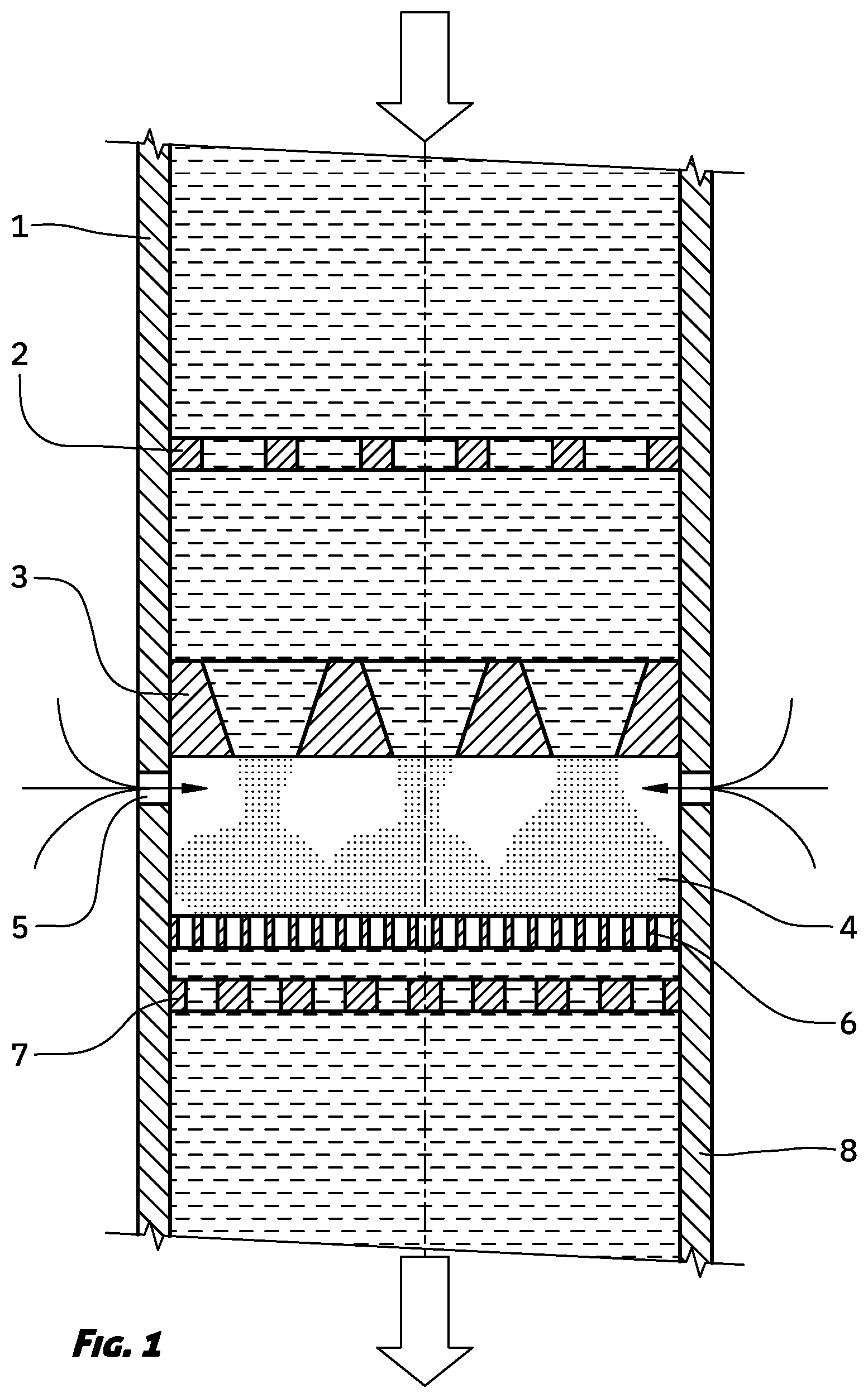
[0006] FIG. 1 shows a schematic cross-sectional view of a device for purification of liquid media,
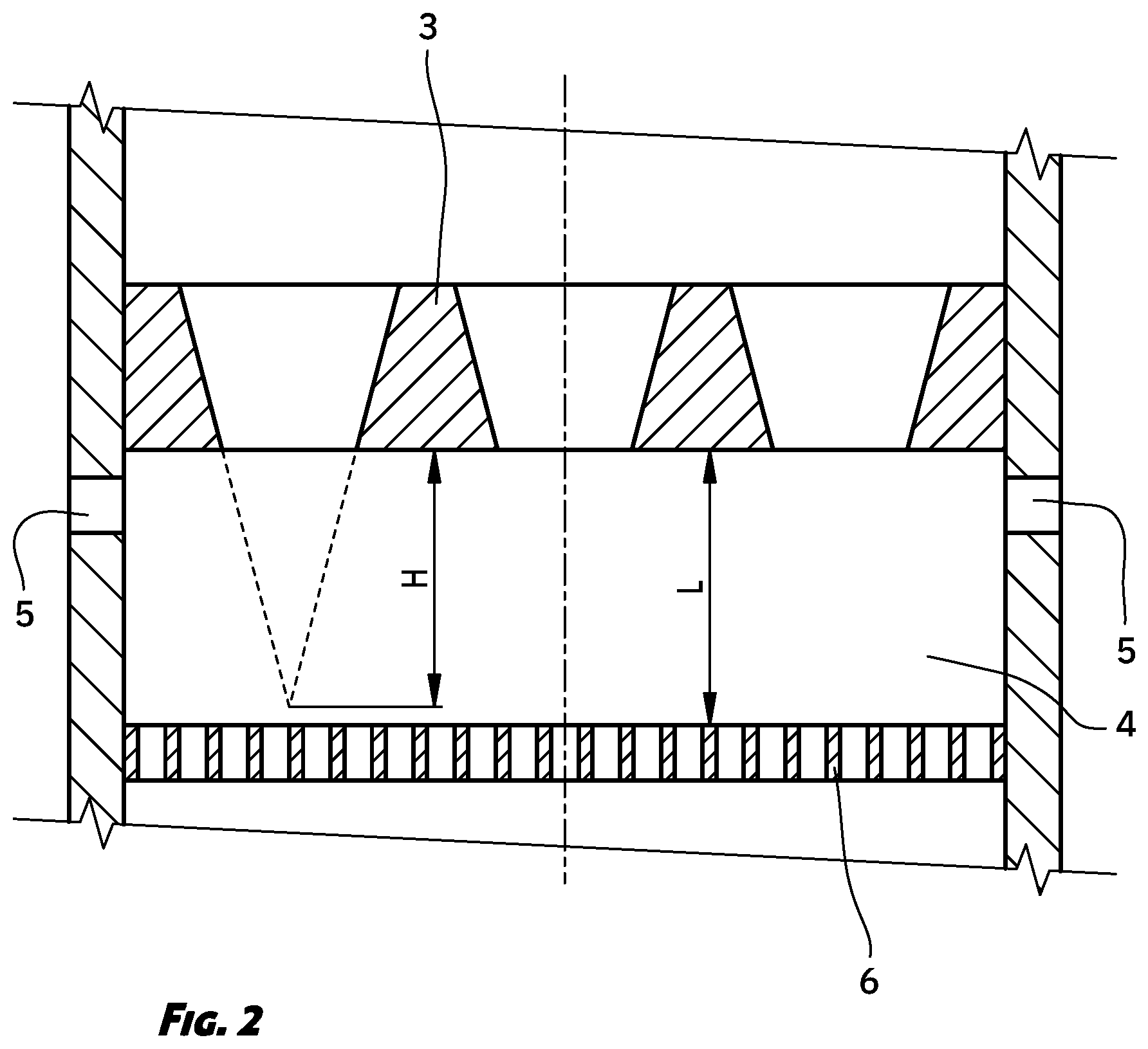
[0007] FIG. 2 shows a detail of the device of FIG. 1.
[0008] A method for liquid media purification starts with feeding fluid to be purified having a first flow rate Q.sub.1 and a supply pressure p.sub.1 trough a supply line 1. Said homogenized fluid is further guided trough a filtration means 2 located downstream, where elimination of rough particles from the fluid and fluid flow streaming take place. At the exit from said filtration means 2 the first stage of the hydrodynamic cavitation of the fluid to be purified takes place, wherein the flow rate is reduced due to decreased free cross-section on a filtration means 2 to a second flow rate Q.sub.2.
[0009] The fluid pre-treated in the above described manner having the second flow Q.sub.2 is then passed through a dispensing means 3, arranged downstream with respect to said filtering means 2. Said dispensing means 3 comprises at least one nozzle 9 through which the liquid from the supply line 1 enters a chamber 4 for the liquid treatment. At the exit of said at least one nozzle 9, hydrodynamic cavitation of the fluid to be purified takes place in the fluid treatment chamber 4, wherein at least one spray jet with a high content of cavitation bubbles is formed of said fluid. The liquid flowing out of the chamber 4 creates a working pressure p.sub.2 in said chamber 4, which is lower than the pressure p.sub.1 of the supplied fluid and simultaneously lower than the ambient pressure, resulting in the suction of the surrounding gas or mixture of gases into the chamber 4.
[0010] A strong hydrodynamic cavitation and simultaneous implosion of cavitation bubbles in a combination with strong under-pressure aeration takes place in said chamber 4. By means of said implosion of cavitation bubbles in the sub-pressure environment, it is achieved strong liquid dispersion, strong oxidation of impurities in the fluid, and substantial removal of gases from the liquid. Said liquid dispersion and the influence of the under-pressure cause an increase of the liquid surface in the flow movement through said chamber 4.
[0011] Consequently, gases and impurities which oxidise are eliminated from the liquid to be purified. In the changed aggregate state, which is a result of said hydrodynamic cavitation, the pressure lower than the ambient pressure, and the supply of gas or gas mixture, dissociation of the molecules of the liquid takes place, which greatly increases the surface of the liquid to be purified. The result is excellent disinfection of said liquid and the elimination of various impurities.
[0012] Said gas or gas mixture is introduced into the chamber 4 through at least one aperture 5 in the wall of the chamber 4, wherein said at least one aperture 5 in said chamber 4 is formed in an area neighbouring the dispensing means 3. Thus, said gas or gas mixture affects dissociated liquid molecules.
[0013] Said working pressure p.sub.2 occurring in said working chamber 4 is stronger than the cohesion forces between the molecules of liquid to be purified and dispersed in working chamber 4, thus, rendering the liquid easily accessible to the influence of the disinfectants. The height of the working pressure p.sub.2 depends on the amount of gas or gas mixture entering the working chamber 4 through at least one aperture 5, and the traction force of the already treated liquid with a pressure p3, which leaves the chamber 4 in the homogenized state via a discharge line 8. It is provided for according to the present invention that the relations between the pressures p.sub.1, p.sub.2, p.sub.3 are such that p.sub.1>p.sub.2 and p.sub.2<p.sub.3.ltoreq.p.sub.1.
[0014] Said gas supplied to said working chamber 4 through said at least one aperture 5 is, for example, selected as oxygen. Furthermore, said gas mixture supplied to said working chamber 4 through said at least one aperture 5, for example, is selected as air.
[0015] Spaced downstream from said dispersing means 3 a first homogenization means 6 is arranged, which is intended to homogenize the purified liquid. Optionally, spaced downstream a second homogenization means 7 is associated with the first homogenization means 6, the discharge line 8 for discharging the purified liquid being connected to said homogenization means 7.
[0016] As mentioned above, it is provided for according to the invention that said dispensing means 3 comprises at least one nozzle 9, by means of which the cavitation of the liquid to be purified is created. Said each nozzle 9 is formed in a manner to converge in the direction of the flow of liquid to be purified. In addition, the preferred form of each nozzle 9 is such that the internal cross-section thereof linearly tappers in the direction of the flow of said liquid.
[0017] A length L of said chamber 4, viewed in the direction of the flow of the fluid to be purified, approximately equals to a distance H between the lower surface of said dispensing means 3 and the apex of an imaginary cone formed by the jet of said liquid coming out of the nozzle 9. In the preferred embodiment of the device for carrying out the method according to the invention, said length L of said chamber 4 lies in the range between about 0.8.times.H and about 1.1.times.H.
[0018] A cross-section A of said at least one aperture 5 or of the sum of all apertures 5 for supplying gas or gas mixture into the working chamber 4 depends on said second flow Q.sub.2 of the liquid to be purified flowing through the cross-section A.sub.t of said at least one nozzle 9 or the sum of all nozzles 9 through which said liquid enters the working chamber 4. In the preferred embodiment of the device for carrying out the process according to the invention, said cross-section A.sub.z is selected as a power function of the second flow Q.sub.2, i.e. A.sub.2=f(Q.sub.2.sup.n). The exponent n is preferably selected in the range of about n=1/2, where the deviation of .+-.15% in the order of magnitude is possible. As an example, it should be noted that, with the flow Q.sub.2=400 l/min of the liquid to be purified, the surface A.sub.z of said at least one aperture 5 and, respectively, the sum of all apertures 5 for supplying gas or a gas mixture into the working chamber 4, is 20 mm.sup.2.+-.15%.
[0019] According to the present invention, it is provided that said at least one aperture 5 for supplying gas or gas mixture is provided with a blocking means, for example a valve or the like. Said measure controls the amount of gas or gas mixture to be delivered into said working chamber 4, and the said pressure p.sub.2.
[0020] Furthermore, it is provided for according to the present invention that said first homogenization means 6 is formed with finer through holes than the filtering means 2 and, respectively, the second homogenization means 7.
[0021] Moreover, it is provided for according to the present invention that the purified liquid leaves the working chamber 4 through the discharge line 8 by means of gravity. However, an embodiment is possible, in which the discharge line 8 is fluidly connected to the pumping means, which discharge the purified liquid by force.
[0022] The method and device for carrying out the method are widely used in many areas, such as treatment of potable, industrial, agricultural and waste water. The method and the device are suitable for the reduction of limescale, the destruction of micro-organisms in the water, the elimination of legionella and pesticides in water, the removal of organic and inorganic pollutants from the water, the increase in the efficiency of the added water disinfectants and the like. In addition, said method and said device significantly reduces the opacity of the water and improves the taste and smell of the water. In addition, it turns out that the method according to the invention leads to the formation of scale in aragonite form, rather than a calcite form.
* * * * *
D00000
D00001
D00002
XML
uspto.report is an independent third-party trademark research tool that is not affiliated, endorsed, or sponsored by the United States Patent and Trademark Office (USPTO) or any other governmental organization. The information provided by uspto.report is based on publicly available data at the time of writing and is intended for informational purposes only.
While we strive to provide accurate and up-to-date information, we do not guarantee the accuracy, completeness, reliability, or suitability of the information displayed on this site. The use of this site is at your own risk. Any reliance you place on such information is therefore strictly at your own risk.
All official trademark data, including owner information, should be verified by visiting the official USPTO website at www.uspto.gov. This site is not intended to replace professional legal advice and should not be used as a substitute for consulting with a legal professional who is knowledgeable about trademark law.