Paper Feeder And Image Forming System
MASUDA; Yoshiyuki
U.S. patent application number 16/538670 was filed with the patent office on 2020-03-05 for paper feeder and image forming system. This patent application is currently assigned to KONICA MINOLTA, INC.. The applicant listed for this patent is KONICA MINOLTA, INC.. Invention is credited to Yoshiyuki MASUDA.
| Application Number | 20200071102 16/538670 |
| Document ID | / |
| Family ID | 69640923 |
| Filed Date | 2020-03-05 |


View All Diagrams
| United States Patent Application | 20200071102 |
| Kind Code | A1 |
| MASUDA; Yoshiyuki | March 5, 2020 |
PAPER FEEDER AND IMAGE FORMING SYSTEM
Abstract
A paper feeder sucking and feeding a paper sheet from a stack of paper sheets loaded on a paper table, the paper feeder includes: a pair of blowing ports that are disposed across a stack of paper sheets and blow air toward a side surface of the stack of paper sheets to float a paper sheet; and a hardware processor that performs blowing control of blowing air to float a paper sheet in a first operation mode in which a height of one blowing ports is different from a height of another blowing ports.
| Inventors: | MASUDA; Yoshiyuki; (Tokyo, JP) | ||||||||||
| Applicant: |
|
||||||||||
|---|---|---|---|---|---|---|---|---|---|---|---|
| Assignee: | KONICA MINOLTA, INC. Tokyo JP |
||||||||||
| Family ID: | 69640923 | ||||||||||
| Appl. No.: | 16/538670 | ||||||||||
| Filed: | August 12, 2019 |
| Current U.S. Class: | 1/1 |
| Current CPC Class: | B65H 3/12 20130101; B65H 3/48 20130101; B65H 7/02 20130101; B65H 2511/414 20130101; B65H 2301/4461 20130101; B65H 2515/112 20130101; B65H 5/228 20130101; B65H 2511/20 20130101; B65H 3/128 20130101 |
| International Class: | B65H 5/22 20060101 B65H005/22; B65H 3/48 20060101 B65H003/48; B65H 3/12 20060101 B65H003/12 |
Foreign Application Data
| Date | Code | Application Number |
|---|---|---|
| Sep 5, 2018 | JP | 2018-165607 |
Claims
1. A paper feeder sucking and feeding a paper sheet from a stack of paper sheets loaded on a paper table, the paper feeder comprising: a pair of blowing ports that are disposed across a stack of paper sheets and blow air toward a side surface of the stack of paper sheets to float a paper sheet; and a hardware processor that performs blowing control of blowing air to float a paper sheet in a first operation mode in which a height of one blowing ports is different from a height of another blowing ports.
2. A paper feeder sucking and feeding a paper sheet from a stack of paper sheets loaded on a paper table, the paper feeder comprising: a pair of blowing ports that are disposed across a stack of paper sheets and blow air toward a side surface of the stack of paper sheets to float a paper sheet; a sheet holder that abuts on a floated paper sheet from above to regulate a floating height of the paper sheet; and a hardware processor that performs blowing control of blowing air to float a paper sheet in a second operation mode in which a height of the at least one sheet holder corresponding to one side surface of a stack of paper sheets is different from a height of the at least one sheet holder corresponding to another side surface of the stack of paper sheets.
3. A paper feeder sucking and feeding a paper sheet from a stack of paper sheets loaded on a paper table, the paper feeder comprising: a pair of blowing ports that are disposed across a stack of paper sheets and blow air toward a side surface of the stack of paper sheets to float a paper sheet; and a hardware processor that performs blowing control of blowing air to float a paper sheet in a third operation mode in which an amount of air blown from one blowing port is different from an amount of air blown from another blowing port.
4. The paper feeder according to claim 1, further comprising a sheet holder that abuts on a floated paper sheet from above to regulate a floating height of the paper sheet, wherein the hardware processor performs the blowing control in a second operation mode in which a height of the at least one sheet holder corresponding to one side surface of a stack of paper sheets is different from a height of the at least one sheet holder corresponding to another side surface of the stack of paper sheets, in addition to the first operation mode.
5. The paper feeder according to claim 1, wherein the hardware processor performs the blowing control in a third operation mode in which an amount of air blown from the one blowing port is different from an amount of air blown from the other blowing port, in addition to the first operation mode.
6. The paper feeder according to claim 2, wherein the hardware processor performs the blowing control in a third operation mode in which an amount of air blown from the one blowing port is different from an amount of air blown from the other blowing ports, in addition to the second operation mode.
7. The paper feeder according to claim 1, further comprising a sheet holder that abuts on a floated paper sheet from above to regulate a floating height of the paper sheet, wherein the hardware processor performs the blowing control in a second operation mode in which a height of the at least one sheet holder corresponding to one side surface of a stack of paper sheets is different from a height of the at least one sheet holder corresponding to another side surface of the stack of paper sheets and a third operation mode in which an amount of air blown from one of the blowing ports is different from an amount of air blown from the other of the blowing ports, in addition to the first operation mode.
8. The paper feeder according to claim 1, further comprising a duct that is connected to each of the blowing ports to guide air blown from a blower to the blowing port, wherein the duct is movable in a vertical direction to adjust the height of the blowing port.
9. The paper feeder according to claim 8, wherein the duct is movable in a vertical direction by a pressure of air.
10. The paper feeder according to claim 9, further comprising a lock mechanism that regulates the movement of the duct to adjust the height of the blowing port.
11. The paper feeder according to claim 2, wherein the at least one sheet holder is provided above the blowing ports.
12. The paper feeder according to claim 11, further comprising a movable mechanism that adjusts the height of the at least one sheet holder.
13. The paper feeder according to claim 1, wherein the hardware processor further includes, as an operation mode in the blowing control, a normal operation mode in which the height of the one blowing port and the height of the other blowing port are aligned, and switches, based on one or both of information on a paper sheet and a floating state of a paper sheet, between the normal operation mode and the first operation mode.
14. The paper feeder according to claim 13, wherein in the first operation mode, the height of the one of the blowing ports or the height of the other of the blowing port is lower than that in the normal operation mode.
15. The paper feeder according to claim 2, wherein the hardware processor further includes, as an operation mode in the blowing control, a normal operation mode in which the height of the sheet holder corresponding to one side surface of a stack of paper sheets and the height of the sheet holder corresponding to another side surface of the stack of paper sheets are aligned, and switches, based on one or both of information on a paper sheet and a floating state of a paper sheet, between the normal operation mode and the second operation mode.
16. The paper feeder according to claim 3, wherein the hardware processor further includes, as an operation mode in the blowing control, a normal operation mode in which the amount of air blown from the one blowing port is equal to the amount of air blown from the other blowing port, and switches, based on one or both of information on a paper sheet and a floating state of a paper sheet, between the normal operation mode and the third operation mode.
17. The paper feeder according to claim 13, wherein the hardware processor switches the operation modes on the basis of a time from floating of a paper sheet to suction of the paper sheet by a sheet suction portion positioned above a stack of paper sheets.
18. The paper feeder according to claim 5, wherein when the amount of air blown from the one blowing port is different from the amount of air blown from the other blowing port, the hardware processor sets a height of the blowing port blowing a larger amount of air lower than a height of the blowing port blowing a smaller amount of air.
19. The paper feeder according to claim 6, wherein when the amount of air blown from the one blowing port is different from the amount of air blown from the other blowing port, the hardware processor sets a height of the sheet holder blowing a smaller amount of air lower than a height of the sheet holder blowing a larger amount of air.
20. An image forming system comprising: the paper feeder according to claim 1; and an image forming apparatus that forms an image on a paper sheet fed from the paper feeder.
21. An image forming system comprising: a paper feeder that sucks and feeds a paper sheet from a stack of paper sheets loaded on a paper table; an image forming apparatus that forms an image on a paper sheet fed from the paper feeder; and a hardware processor that controls the paper feeder and the image forming apparatus; wherein the paper feeder includes a pair of blowing ports that are disposed across a stack of paper sheets and blow air toward a side surface of the stack of paper sheets to float a paper sheet, and the hardware processor performs blowing control of blowing air to float a paper sheet in a first operation mode in which a height of one blowing port is different from a height of another blowing port.
22. An image forming system comprising: a paper feeder that sucks and feeds a paper sheet from a stack of paper sheets loaded on a paper table; an image forming apparatus that forms an image on a paper sheet fed from the paper feeder; and a hardware processor that controls the paper feeder and the image forming apparatus; wherein the paper feeder includes: a pair of blowing ports that are disposed across a stack of paper sheets and blow air toward a side surface of the stack of paper sheets to float a paper sheet, and; a sheet holder that abuts on a floated paper sheet from above to regulate a floating height of the paper sheet, and the hardware processor performs blowing control of blowing air to float a paper sheet in a second operation mode in which a height of the at least one sheet holder corresponding to one side surface of a stack of paper sheets is different from a height of the at least one sheet holder corresponding to another side surface of the stack of paper sheets.
23. An image forming system comprising: a paper feeder that sucks and feeds a paper sheet from a stack of paper sheets loaded on a paper table; an image forming apparatus that forms an image on a paper sheet fed from the paper feeder; and a hardware processor that controls the paper feeder and the image forming apparatus; wherein the paper feeder includes a pair of blowing ports that are disposed across a stack of paper sheets and blow air toward a side surface of the stack of paper sheets to float a paper sheet, and the hardware processor performs blowing control of blowing air to float a paper sheet in a third operation mode in which an amount of air blown from one blowing port is different from an amount of air blown from another blowing port.
24. An image forming system comprising: the paper feeder according to claim 2; and an image forming apparatus that forms an image on a paper sheet fed from the paper feeder.
25. An image forming system comprising: the paper feeder according to claim 3; and an image forming apparatus that forms an image on a paper sheet fed from the paper feeder.
Description
[0001] The entire disclosure of Japanese patent Application No. 2018-165607, filed on Sep. 5, 2018, is incorporated herein by reference in its entirety.
BACKGROUND
Technological Field
[0002] The present invention relates to a paper feeder and an image forming system.
Description of the Related Art
[0003] Image forming systems are known to serially perform various processing including image formation. Such an image forming system is configured by arranging one or more devices in series according to a specification required by a user. An apparatus constituting the image forming system includes, in addition to an image forming apparatus that forms an image, for example, a paper feeder (large capacity paper feeder) that holds a large amount of paper sheets and feeds the paper sheets to the image forming apparatus.
[0004] The paper feeder includes a paper table that loads a plurality of paper sheets stacked in a thickness direction, that is, a stack of paper sheets thereon, and a sheet feed portion that feeds paper sheets. The sheet feed portion feeds a paper sheet (uppermost paper sheet) one by one from the stack of paper sheets loaded on the paper table. As the sheet feed portion, a configuration for sucking and feeding a paper sheet is known, and the paper feeder includes a side surface blowing portion that blows air to a side surface of the stack of paper sheets in a sheet transport direction to float a paper sheet.
[0005] This type of paper feeder floats not only the uppermost paper sheet but also the second and subsequent paper sheets due to air blowing. Therefore, the suction of the uppermost paper sheet by the sheet feed portion requires fanning the second and subsequent paper sheets positioned under the uppermost paper sheet to feed the uppermost paper sheet. Such a configuration requires a long time to float a paper sheet, reducing productivity. On the other hand, to ensure the productivity, there is no sufficient time to fan the paper sheets, and multi-feed is likely to be caused. In addition, in a case where it is difficult to float a paper sheet, suction of the paper sheet is late so that no paper sheet may be fed.
[0006] Therefore, for example, JP 2014-1061 A discloses a method of increasing the amount of air blown to a side surface of a stack of paper sheets.
[0007] However, the amount of air blown to the side surface of the stack of paper sheets depends on the configuration of a blower. Therefore, there is a problem that in a case where a sufficient floating state cannot be obtained even with the maximum amount of air of the blower, a blower outputting higher amount of air is required.
SUMMARY
[0008] The present invention has been made in view of the above circumstances, and an object of the invention is to provide a paper feeder and an image forming system which are capable of achieving stable sheet feed performance by reducing a time required to float a paper sheet.
[0009] To achieve the abovementioned object, according to an aspect of the present invention, there is provided a paper feeder sucking and feeding a paper sheet from a stack of paper sheets loaded on a paper table, and the paper feeder reflecting one aspect of the present invention comprises: a pair of blowing ports that are disposed across a stack of paper sheets and blow air toward a side surface of the stack of paper sheets to float a paper sheet; and a hardware processor that performs blowing control of blowing air to float a paper sheet in a first operation mode in which a height of one blowing ports is different from a height of another blowing ports.
BRIEF DESCRIPTION OF THE DRAWINGS
[0010] The advantages and features provided by one or more embodiments of the invention will become more fully understood from the detailed description given hereinbelow and the appended drawings which are given by way of illustration only, and thus are not intended as a definition of the limits of the present invention:
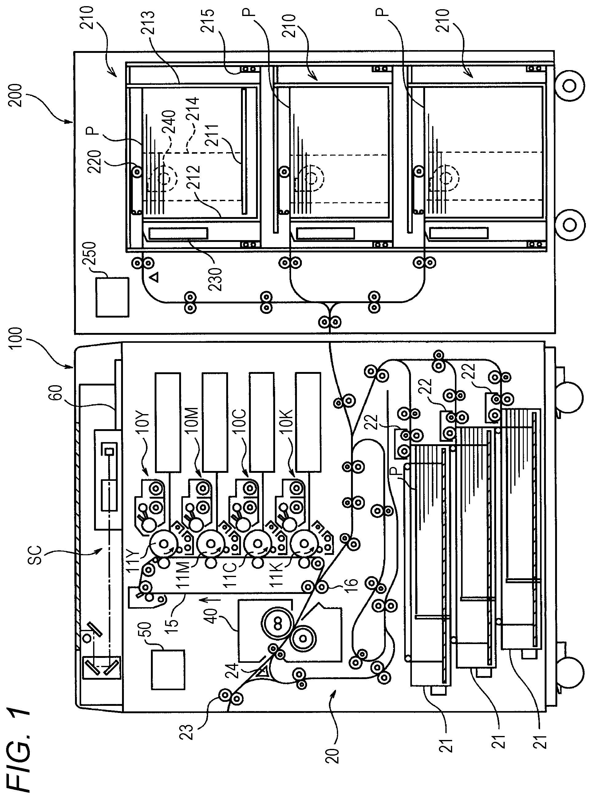
[0011] FIG. 1 is a front view schematically illustrating a configuration of an image forming system according to an embodiment of the present invention;
[0012] FIG. 2 is a front view schematically illustrating a configuration of a paper feed unit;
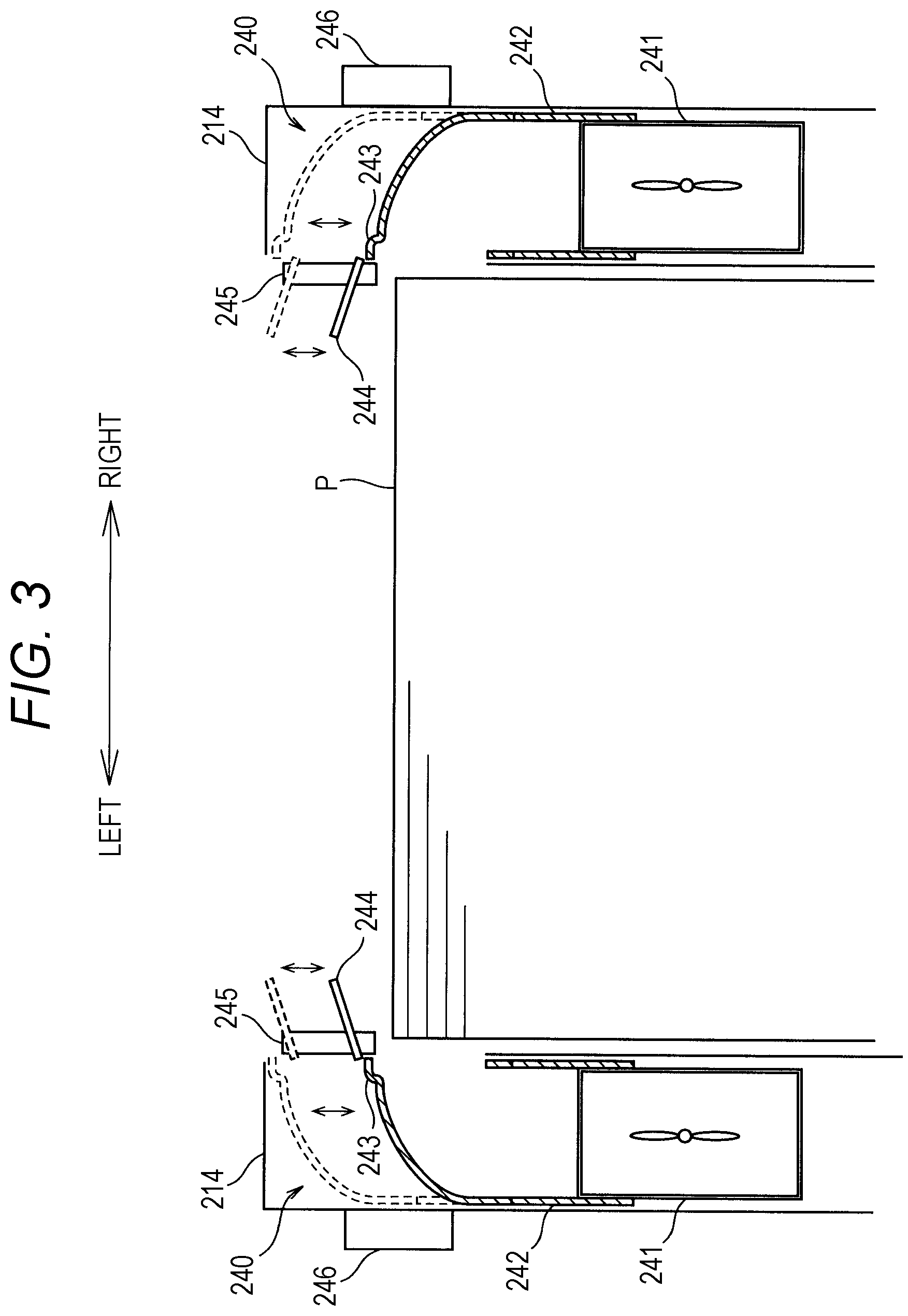
[0013] FIG. 3 is a diagram schematically illustrating the configurations of side end blowing portions;
[0014] FIGS. 4A to 4C are explanatory diagrams illustrating a side end blowing portion in detail;
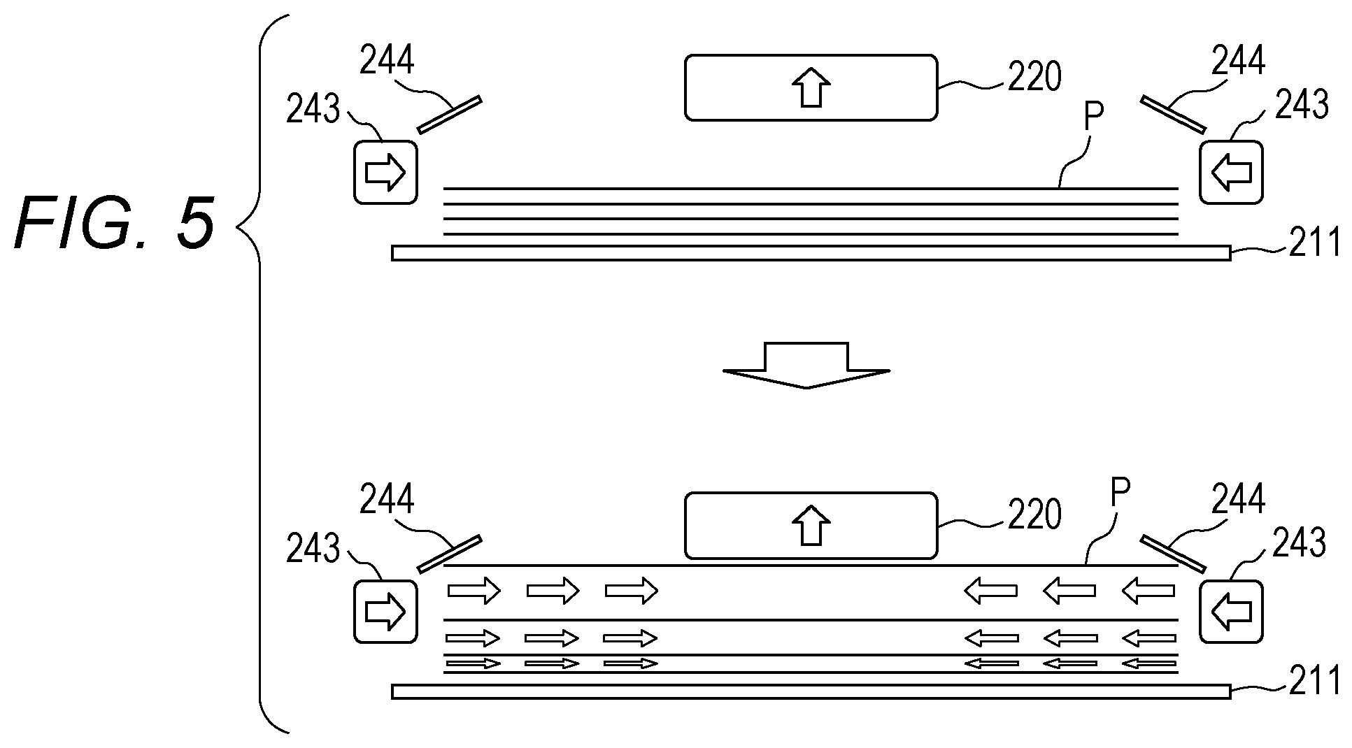
[0015] FIG. 5 is an explanatory diagram of a normal operation mode;
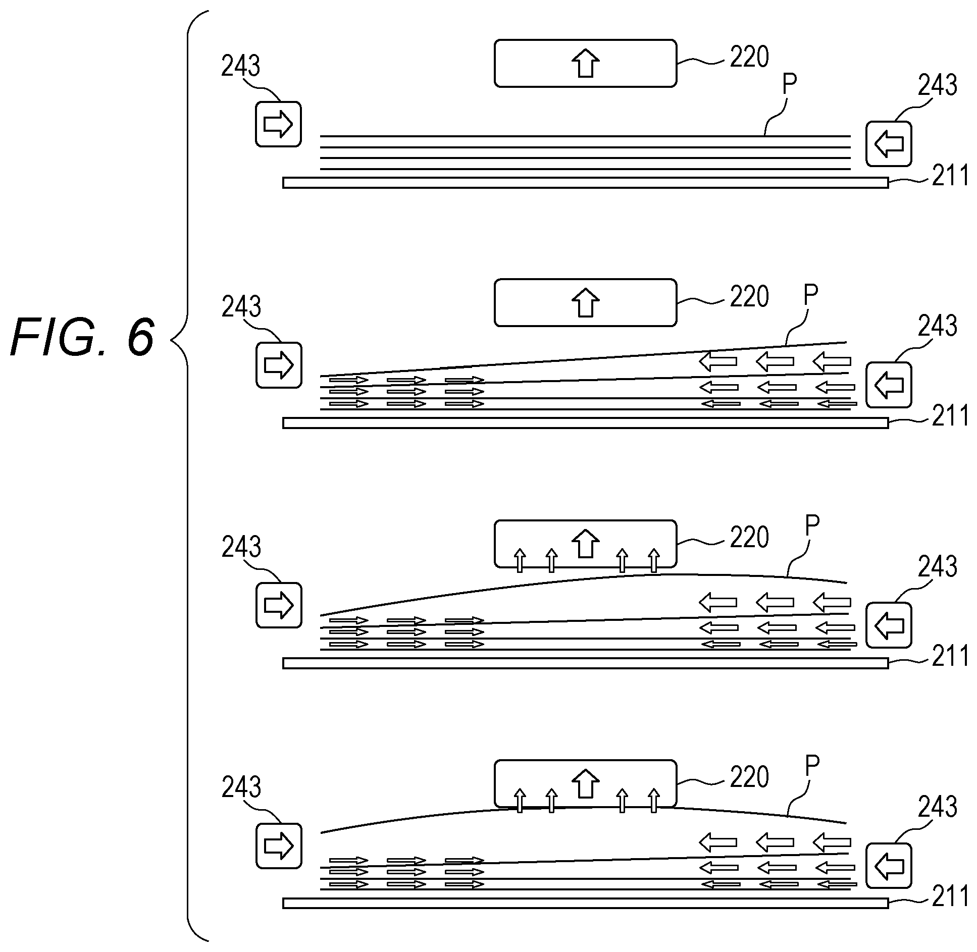
[0016] FIG. 6 is an explanatory diagram of a first operation mode;
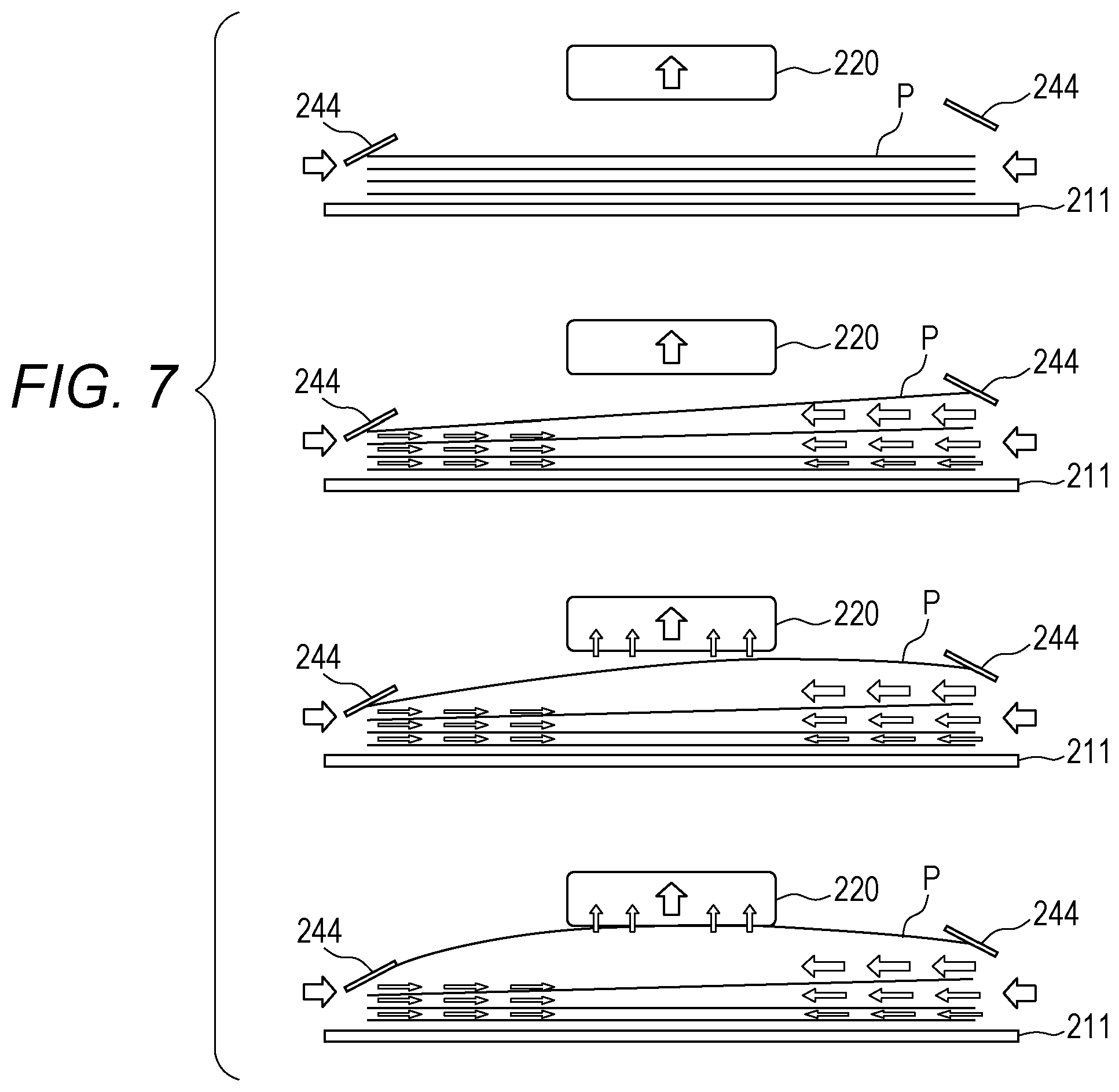
[0017] FIG. 7 is an explanatory diagram of a second operation mode;
[0018] FIG. 8 is an explanatory diagram of a third operation mode;
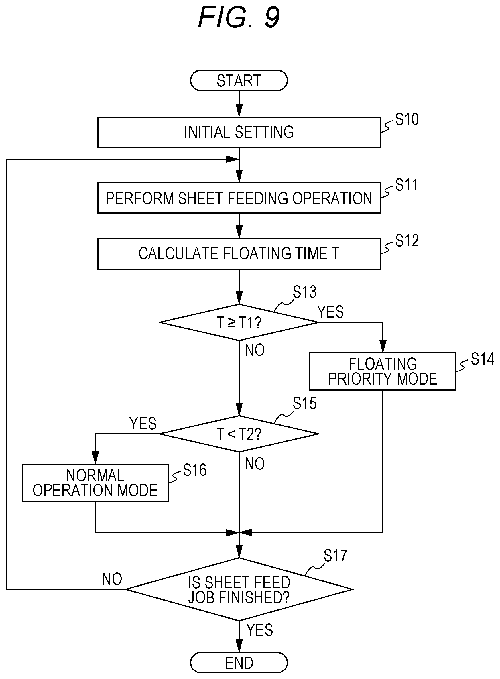
[0019] FIG. 9 is a flowchart illustrating a sheet feeding process;
[0020] FIG. 10 is a table defining relationships between operation modes and information on paper sheets; and
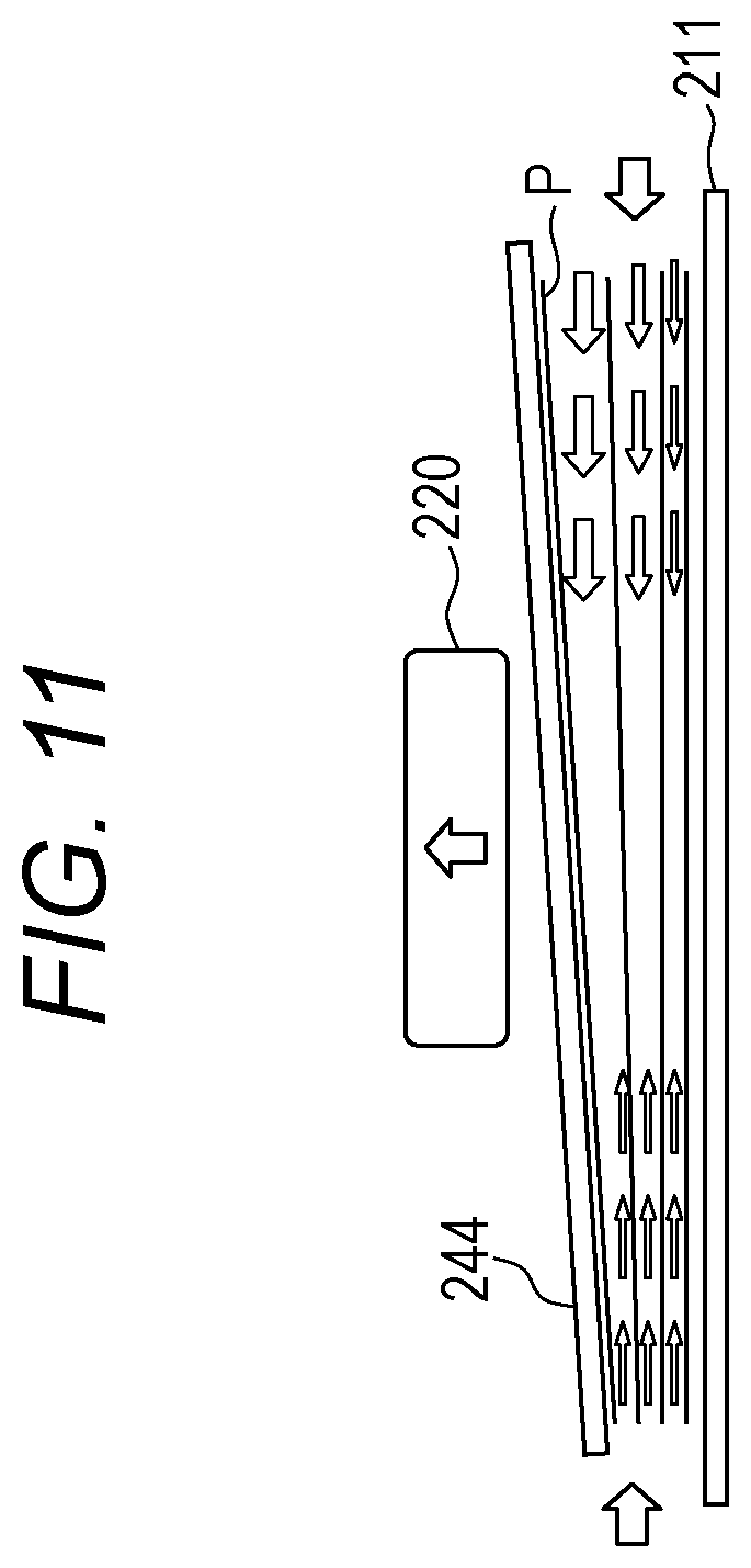
[0021] FIG. 11 is an explanatory diagram of a modification of a sheet holder.
DETAILED DESCRIPTION OF EMBODIMENTS
[0022] Hereinafter, one or more embodiments of the present invention will be described with reference to the drawings. However, the scope of the invention is not limited to the disclosed embodiments.
[0023] FIG. 1 is a front view schematically illustrating a configuration of an image forming system according to the present embodiment. The image forming system performs predetermined processing including image formation on a paper sheet P and includes a plurality of apparatuses. The image forming system according to the present embodiment includes an image forming apparatus 100 and a large capacity paper feeder 200. These apparatuses are arranged in the order of the large capacity paper feeder 200 and the image forming apparatus 100 from an upstream side to a downstream side in a sheet transport direction, but the individual apparatuses may be accommodated in the same housing.
[0024] The image forming apparatus 100 forms an image on a paper sheet P fed from the large capacity paper feeder 200 or a paper sheet P held in the image forming apparatus 100. The image forming apparatus 100 is, for example, an electrophotographic image forming apparatus and, in particular, a so-called tandem color image forming apparatus having a plurality of photoreceptors disposed in a vertical direction to face one intermediate transfer belt and forming a full-color image. The image forming apparatus 100 mainly includes a document reader SC, four sets of image forming units 10Y, 10M, 10C, and 10K, a fuser 40, and a control unit 50, and these elements are stored in one casing.
[0025] The document reader SC scans and exposes a document by using an exposure device and reads reflected light from the document by using a line image sensor to obtain an image signal. The image signal is subjected to processing, such as A/D conversion, shading correction, and compression, and then is input as image data to the control unit 50. The image data input to the control unit 50 is not limited to image data read by the document reader SC and may include, for example, image data received from a personal computer, which is connected to the image forming apparatus 100, or another image forming apparatus or image data read from a portable recording medium, such as a semiconductor memory.
[0026] The four image forming units 10Y, 10M, 10C, and 10K include the image forming unit 10Y forming a yellow (Y) image, the image forming unit 10M forming a magenta (M) image, the image forming unit 10C forming a cyan (C) image, and the image forming unit 10K forming a black (K) image.
[0027] The image forming unit 10Y includes a photoreceptor drum 11Y and a charged portion, an optical writing unit, a developing device, and a drum cleaner which are disposed around the photoreceptor drum 11Y. The photoreceptor drum 11Y has a surface which is uniformly charged by the charged portion, and thus a latent image is formed on the photoreceptor drum 11Y by scanning exposure by the optical writing unit. In the developing device, toner develops the latent image on the photoreceptor drum 11Y to visualize the latent image. Thereby, an image (toner image) corresponding to yellow is formed on the photoreceptor drum 11Y. Images formed on the photoreceptor drum 11Y are sequentially transferred to a predetermined position on an intermediate transfer belt 15, which is an endless belt, by a primary transfer roller.
[0028] The remaining image forming units 10M, 10C, and 10K include photoreceptor drums 11M, 11C, and 11K and charged portions, optical writing units, developing devices, and drum cleaners which are disposed around the photoreceptor drums 11M, 11C, and 11K, and detailed configurations thereof are similar to that of the image forming unit 10Y.
[0029] An image transferred onto the intermediate transfer belt 15 is transferred by a secondary transfer roller 16 onto a paper sheet P transported at predetermined timing by a paper transport unit 20. The secondary transfer roller 16 is disposed in pressure-contact with the intermediate transfer belt 15, and a transfer nip is formed between the secondary transfer roller 16 and the intermediate transfer belt 15.
[0030] The paper transport unit 20 transports a paper sheet P fed from a paper tray 21 by a paper feed roller 22 or a paper sheet P fed from the large capacity paper feeder 200 through a transport path. The paper transport unit 20 includes transport rollers, a conveyance guide, and the like. In addition, a paper exit roller 23 and a switching gate 24, which will be described later, also partially constitute the paper transport unit 20.
[0031] The fuser 40 is configured to fix an image having been transferred onto a paper sheet P. The fuser 40 is constituted by, for example, a pair of fusing rollers that are brought into pressure contact with each other to form a fusing nip, and a heater that heats one of the fusing rollers. While the paper sheet P passes through the fusing nip, the fuser 40 fixes the transferred image on the paper sheet P by using the pressure of the pair of fusing rollers and the heat of the fusing roller. The paper sheet P subjected to the fixing processing is discharged to the outside of the apparatus by the paper exit roller 23.
[0032] To form an image also on the back side of the paper sheet P, the paper sheet P, on the front side of which the image has been formed is transported to the sheet refeed path by the switching gate 24. In the sheet refeed path, a trailing end of the transported paper sheet P is held by reverse rollers, and then, the paper sheet P is turned over by reverse feeding. The paper sheet P which has been turned over is transported by a plurality of transport rollers and joined to a transport path positioned upstream from the secondary transfer roller 16 to form an image on the back side of the paper sheet.
[0033] The control unit 50 controls the operation of the image forming apparatus 100. As the control unit 50, a microcomputer mainly including a CPU, a ROM, a RAM, and an I/O interface is usable. The CPU executes various programs to control the operation of the image forming apparatus 100 (processor). The ROM stores various programs executed by the CPU, in the form of program codes readable by the CPU. The ROM also stores data necessary for execution of the programs. The RAM is a memory serving as a storage area for work. The programs and data stored in the ROM are loaded into the RAM when read by the CPU. Then, the CPU performs various processing on the basis of the programs and data loaded into the RAM.
[0034] An operation panel 60 is an input unit capable of inputting desired information according to information displayed on a display. For the operation panel 60, a touch panel system or the like can be employed. The user can set the contents of a job (information (sheet size, paper type, etc.) about the paper sheet P, density, magnification, etc. of an image) through the operation on the operation panel 60. The set information is acquired by the control unit 50. The operation panel 60 is controlled by the control unit 50 to also function as a display unit for displaying various information to the user.
[0035] The large capacity paper feeder 200 is a paper feeder for feeding paper sheets P. The large capacity paper feeder 200 includes one or more paper feed units 210, for example, three paper feed units 210 disposed in upper, middle, and lower stages, and a control unit 250, and these elements are stored in one casing.
[0036] FIG. 2 is a front view schematically illustrating a configuration of the paper feed unit 210. The paper feed unit 210 stores a plurality of paper sheets P (stack of paper sheets), and feeds a paper sheet P (uppermost paper sheet P) one by one from the stack of paper sheets. The paper feed unit 210 mainly includes a paper table 211, a leading end adjusting member 212, a trailing end adjusting member 213, a side end adjusting member 214, a sheet feed portion 220, a leading end blowing portion 230, and a side end blowing portion 240. The paper feed unit 210 is provided with a guide rail 215 so that the paper feed unit 210 is drawable from the casing of the large capacity paper feeder 200.
[0037] In the paper feed unit 210, the stack of paper sheets is loaded on the paper table 211. The paper table 211 is provided with an electrically-driven lift mechanism so as to move in a vertical direction.
[0038] The leading end adjusting member 212 regulates a leading end of each paper sheet P loaded on the paper table 211, that is, a surface (leading end surface) of the stack of paper sheets positioned downstream from the leading end adjusting member 212 in a sheet transport direction.
[0039] The trailing end adjusting member 213 regulates the trailing end of each paper sheet P loaded on the paper table 211, that is, a surface (trailing end face) of the stack of paper sheets positioned upstream from the trailing end adjusting member 213 in the sheet transport direction. The trailing end adjusting member 213 is configured to be movable in the sheet transport direction, and the position thereof is adjusted according to sheet size.
[0040] In the trailing end adjusting member 213, a height sensor (not illustrated) is disposed to detect the height of the stack of paper sheets loaded on the paper table 211. The control unit 250 drives the lift mechanism on the basis of a signal from the height sensor to control the paper table 211 to lift and lower. Owing to this control, the uppermost paper sheet P of the stack of paper sheets loaded on the paper table 211 is maintained at a constant height.
[0041] The side end adjusting member 214 regulates a side end of each paper sheet P loaded on the paper table 211, that is, a surface (side surface) of the stack of paper sheets parallel to the sheet transport direction. The side end adjusting member 214 is provided at two places corresponding to both side surfaces (right and left side surfaces) of the stack of paper sheets. In other words, the side end adjusting members 214 are arranged to face each other across the stack of paper sheets. One or both of the side end adjusting members 214 is configured to be movable in a direction (sheet width direction) orthogonal to the sheet transport direction, and the position thereof is adjusted according to sheet size.
[0042] The sheet feed portion 220 is disposed above the paper table 211 (paper sheet P) so as to face the paper table 211. The sheet feed portion 220 is disposed to be separated from the uppermost paper sheet P of the stack of paper sheets loaded on the paper table 211 by a fixed distance. The sheet feed portion 220 sucks a paper sheet P (uppermost paper sheet P) having been floated from the stack of paper sheets by blowing air and feeds the paper sheet P to the transport path. The sheet feed portion 220 mainly includes a sheet transport portion 221 and a suction portion 226.
[0043] The sheet transport portion 221 has a function of transporting (feeding) a sucked paper sheet P forward and includes an endless suction belt 221a, a driving roller 221b, and driven rollers 221c, and the suction belt 221a is stretched around the driving roller 221b and the driven rollers 221c. The suction belt 221a turns as the driving roller 221b is rotationally driven, and a belt area (lower belt area) facing the paper sheet P moves in the sheet transport direction. The suction belt 221a is provided with a plurality of through-holes (not illustrated) each having a small diameter.
[0044] The suction portion 226 sucks a floated paper sheet P onto the suction belt 221a. The suction portion 226 is disposed inside the suction belt 221a and faces the paper sheet P across the suction belt 221a. The suction portion 226 includes a suction fan for sucking air, and a duct disposed inside the suction belt 221a to guide air to the suction fan. At a lower portion of the duct, a suction port facing the suction belt 221a is defined. Operation of the suction fan reduces the pressure inside the suction belt 221a to a negative pressure. Thus, the flow of air from the lower side of the suction belt 221a to the duct is formed, and the paper sheet P is sucked.
[0045] Furthermore, the sheet feed portion 220 is provided with a suction sensor (not illustrated) that detects suction of a paper sheet P to the suction belt 221a. Information detected by the suction sensor is read by the control unit 250.
[0046] The leading end blowing portion 230 is disposed on the leading end surface of the stack of paper sheets and in the vicinity of the sheet feed portion 220. The leading end blowing portion 230 blows air to the stack of paper sheets loaded on the paper table 211 from the leading end side thereof. The air blow introduces air between the uppermost paper sheet P and the second and subsequent sheets P, fanning the uppermost paper sheet P and the second and subsequent paper sheets P.
[0047] The leading end blowing portion 230 mainly includes a blower 231 and a blowing port 232. The blower 231 is, for example, a multi-vane fan (sirocco fan). The blowing port 232 blows air blown from the blower 231 toward the top of the stack of paper sheets.
[0048] FIG. 3 is a diagram schematically illustrating the configurations of the side end blowing portions 240. The side end blowing portions 240 are disposed at two places corresponding to right and left side surfaces of the stack of paper sheets. In the present embodiment, the side end blowing portions 240 are provided inside the side end adjusting members 214. Similar to the pair of side end adjusting members 214, a pair of the side end blowing portions 240 are arranged to face each other across the stack of paper sheets. The individual side end blowing portions 240 are configured to be symmetrical about the stack of paper sheets.
[0049] Each of the side end blowing portions 240 includes a blower 241, a duct 242, a blowing port 243, and a sheet holder 244. The blower 241 is, for example, a multi-vane fan (sirocco fan) and blows air. The duct 242 guides air blown from the blower 241 to the blowing port 243. The duct 242 is configured so that air flows in a vertical direction. The blowing port 243 is connected to an upper portion of the duct 242. The blowing port 243 blows air flowing through the duct 242 toward a side surface of the stack of paper sheets. Air blown from the blowing port 243 to the side surface of the stack of paper sheets functions as air for floating an uppermost paper sheet P. The sheet holder 244 abuts on the floated uppermost paper sheet P from above to regulate a floating height of the paper sheet P. The sheet holder 244 is provided above the blowing port 243 and extends toward the center of the stack of paper sheets. A movable mechanism 245 for adjusting the height of the sheet holder 244 is connected to the sheet holder 244. Operation of the movable mechanism 245 is controlled by the control unit 250.
[0050] FIGS. 4A to 4C are explanatory diagrams illustrating a side end blowing portion 240 in detail. In the side end blowing portion 240, the duct 242 is movable in a vertical direction within a movable range from an upper limit position to a lower limit position. When the blower 241 is not in operation, the duct 242 stays at the lower limit position by its own weight, as illustrated in FIG. 4A. On the other hand, when the blower 241 is in operation, the duct 242 rises to the upper limit position by the pressure of air blown from the blower 241, as illustrated in FIG. 4B, and keeps staying at that position. When the blower 241 stops, the duct 242 is lowered to the lower limit position by its own weight, as illustrated in FIG. 4A.
[0051] As one of the features of the present embodiment, each of the side end blowing portions 240 includes a lock mechanism 246. The lock mechanism 246 restricts the movement of the duct 242 and adjusts the height of the blowing port 243. For the lock mechanism 246, a method using an abutment member or a method using a solenoid can be considered. The abutment member is configured to be able to extend above the duct 242 located at the lower limit position. When the abutment member extends, the duct 242 abuts against the abutment member, even if the blower 241 operates, and the duct 242 is restricted from rising. On the other hand, in the method of using a solenoid, a plunger of the solenoid is connected to the duct 242. When the solenoid is pulled, the duct 242 connected to the plunger is restricted from rising, even if the blower 241 operates. Thus, the operation of the lock mechanism 246 restricts the duct 242 at the lower limit position, even if the blower 241 operates (FIG. 4C). The operation of the lock mechanism 246 is controlled by the control unit 250.
[0052] As described above, the height of the blowing port 243 connected to the duct 242 is adjusted in response to rising and lowering of the duct 242. When the duct 242 is located at the upper limit position, that is, when the pressure of air is applied according to the operation of the blower 241, the blowing port 243 is positioned at a preset normal blowing position (FIG. 4B). In the normal blowing position, only a lower side area of the blowing port 243 faces a side surface of the stack of paper sheets, and an upper side area of the blowing port 243 protrudes upward above the uppermost paper sheet P. In contrast, when the duct 242 is located at the lower limit position, that is, when the blower 241 is not in operation, or when the lock mechanism 246 is operated even though the blower 241 operates, the blowing port 243 is set to a position lower than the normal blowing position. At this position, substantially the entire area of the blowing port 243 faces the side surface of the stack of paper sheets.
[0053] Adjusting the height of the blowing port 243 enables adjustment of an area of the blowing port 243 facing the side surface of the stack of paper sheets. In a case where the area of the blowing port 243 facing the side surface of the stack of paper sheets is smaller, a ratio of air blown to the side surface of the stack of paper sheets to air output from the blowing port 243 decreases. In contrast, in a case where the area of the blowing port 243 facing the side surface of the stack of paper sheets is larger, the ratio of air blown to the side surface of the stack of paper sheets to air blown from the blowing port 243 increases. In other words, adjusting the height of the blowing port 243 enables adjustment of the ratio of air blown to the side surface of the stack of paper sheets.
[0054] The control unit 250 controls operation of the large capacity paper feeder 200. As the control unit 250, a microcomputer mainly including a CPU, a ROM, a RAM, and an I/O interface is usable. The CPU executes various programs to control the operation of the large capacity paper feeder 200 (processor). The ROM stores various programs executed by the CPU, in the form of program codes readable by the CPU. The ROM also stores data necessary for execution of the programs. The RAM is a memory serving as a storage area for work. The programs and data stored in the ROM are loaded into the RAM when read by the CPU. Then, the CPU performs various processing on the basis of the programs and data loaded into the RAM.
[0055] In the present embodiment, the control unit 250 performs a sheet feeding operation of feeding a paper sheet P (uppermost paper sheet P) from the stack of paper sheets. Specifically, the control unit 250 controls the suction portion 226 to suck a paper sheet P (uppermost paper sheet P) from the stack of paper sheets loaded on the paper table 211 (suction control). At this time, the control unit 250 controls the side end blowing portions 240 to blow air for floating the paper sheet P (blowing control). Next, when the control unit 250 determines, via the suction sensor, that the paper sheet P has been sucked, the control unit 250 finishes the blowing control. Then, the control unit 250 controls the leading end blowing portion 230 to blow air from the leading end side of the paper sheet P, fanning the uppermost paper sheet P and the second and subsequent sheets P (fanning control). Similarly, the control unit 250 controls the sheet transport portion 221 to feed the paper sheet P forward to the transport path (transport control). When the paper sheet P is fed to the transport path, the control unit 250 finishes the fanning control and transport control. This series sheet feeding operation is repeated for a new uppermost paper sheet P each time the paper sheet P is fed.
[0056] The outline of the blowing control which is one of the features of the present embodiment will be described. In the following description, a side end blowing portion 240 facing the right side of a stack of paper sheets is referred to as a side end blowing portion 240 on the right side, and a side end blowing portion 240 facing the left side of the stack of paper sheets is referred to as a side end blowing portion 240 on the left side (elements constituting each side end blowing portion 240 are similarly expressed).
[0057] The control unit 250 includes a plurality of operation modes to perform the blowing control. The control unit 250 basically performs blowing control in a normal operation mode.
[0058] FIG. 5 is an explanatory diagram of the normal operation mode. In the normal operation mode, the side end blowing portions 240 on the right and left sides are operated under the same conditions. Specifically, in the normal operation mode, the height of a blowing port 243 on the left side and the height of a blowing port 243 on the right side are aligned at the normal blowing position. In addition, the height of a sheet holder 244 on the left side and the height of a sheet holder 244 on the right side are aligned. Furthermore, the amount of air blown from the blowing port 243 on the left side is equal to the amount of air blown from the blowing port 243 on the right side.
[0059] While, when determining a predetermined switching condition, the control unit 250 switches the normal operation mode to a floating priority mode in which the right side or left side of a paper sheet P is positively floated. The floating priority mode is achieved in one of a first operation mode, a second operation mode, and a third operation mode, which will be described later or in a combined mode of two or more thereof. In the following description, an example will be described in which a right side end of a paper sheet P is floated.
[0060] FIG. 6 is an explanatory diagram of the first operation mode. In the first operation mode, the height of the blowing port 243 on the right side is different from the height of the blowing port 243 on the left side. Specifically, the height of the blowing port 243 on the left side is set to a normal blowing position, and the height of the blowing port 243 on the right side is set to a position lower than the normal blowing position. In other words, the height of the blowing port 243 on the right side is lower than the height of the blowing port 243 on the left side.
[0061] The ratio of air blown to a side surface of the stack of paper sheets is larger at the blowing port 243 at the lower position than at the blowing port 243 at the normal blowing position. Therefore, on the right side surface of the stack of paper sheets, the amount of air entering between the paper sheets P increases, and a right end of an uppermost paper sheet P is floated higher.
[0062] When the right end of the uppermost paper sheet P is floated higher, the floated area of the paper sheet P approaches the sheet feed portion 220 and is thus assisted by the suction of the sheet feed portion 220. Therefore, even when the uppermost paper sheet P is not entirely floated, the paper sheet P is sucked to the sheet feed portion 220 from the right end of the paper sheet P. Therefore, even in a paper sheet P requiring a time to float when air is uniformly blown from both sides in the normal operation mode, the floating priority mode (first operation mode) is applicable, and only the right side or left side of the uppermost paper sheet P is positively floated, reducing a time required for floating. Thus, stable sheet feed performance is ensured.
[0063] FIG. 7 is an explanatory diagram of the second operation mode. In the second operation mode, the height of the sheet holder 244 on the right side is different from the height of the sheet holder 244 on the left side. Specifically, the height of the sheet holder 244 on the left side is set lower than the height of the sheet holder 244 on the right side.
[0064] In this case, at the left end of a paper sheet P, the sheet holder 244 restricts the paper sheet P from floating. On the other hand, at the right end of the paper sheet P, there is a sufficient distance with respect to the sheet holder 244, and the paper sheet P is allowed to float. When air is blown in this state, the sheet holder 244 on the left side acts as a fulcrum, and the right end of the paper sheet P is floated higher.
[0065] When the right end of the paper sheet P is floated higher, the floated area of the paper sheet P approaches the sheet feed portion 220 and is thus assisted by the suction of the sheet feed portion 220. Therefore, even when the paper sheet P is not entirely floated, the paper sheet P is sucked to the sheet feed portion 220 from the right end of the paper sheet P. Therefore, even in a paper sheet P requiring a time to float when air is uniformly blown from both sides in the normal operation mode, the floating priority mode (second operation mode) is applicable, and only the right side or left side of the uppermost paper sheet P is positively floated, reducing a time required for floating. Thus, stable sheet feed performance is ensured.
[0066] FIG. 8 is an explanatory diagram of the third operation mode. In the third operation mode, the amount of air blown from the blowing port 243 on the right side is different from the amount of air blown from the blowing port 243 on the left side. Specifically, the amount of air blown from the blowing port 243 on the right side is increased. In this case, the ratio of air blown to a side surface of the stack of paper sheets from the blowing port 243 on the right side is increased. Thus, at the right end of the stack of paper sheets, the amount of air entering between paper sheets P increases, and the floating amount increases.
[0067] When the right end of the uppermost paper sheet P is floated higher, the floated area of the paper sheet P approaches the sheet feed portion 220 and is thus assisted by the suction of the sheet feed portion 220. Therefore, even when the uppermost paper sheet P is not entirely floated, the paper sheet P is sucked to the sheet feed portion 220 from the right end of the paper sheet P. Therefore, even in a paper sheet P requiring a time to float when air is uniformly blown from both sides in the normal operation mode, the floating priority mode (third operation mode) is applicable, and only the right side or left side of the uppermost paper sheet P is positively floated, reducing a time required for floating. Thus, stable sheet feed performance is ensured.
[0068] Note that in a case where the first operation mode and the third operation mode are combined, the height of a blowing port 243 blowing a larger amount of air is preferably set lower than the height of a blowing port 243 blowing a smaller amount of air. Similarly, when combining the second operation mode and the third operation mode, the height of a sheet holder 244 positioned on a side where a smaller amount of air is blown is preferably set lower than a sheet holder 244 positioned on a side where a larger amount of air is blown.
[0069] Switching between the normal operation mode and the floating priority mode is performed on the basis of one or both of the information on the paper sheet P and a floating state of the paper sheet P. The information on the paper sheet P represents the basis weight and length of the paper sheet. In a case of a paper sheet P having a large basis weight or a paper sheet P having a large length, it may take time to float even if air is blown in the normal operation mode. Therefore, the control unit 250 is configured to determine to switch operation modes in accordance with the information on the paper sheet P. Thus, a time required for floating can be reduced, and stable sheet feed performance can be ensured. Furthermore, the control unit 250 is configured to monitor an actual floating state of the paper sheet P to switch operation modes according to the paper sheet P requiring a time for floating. Thus, a time required for floating can be reduced, and stable sheet feed performance can be ensured.
[0070] Hereinafter, the operation of the image forming system according to the present embodiment, specifically, a sheet feeding process for paper sheets P in the large capacity paper feeder 200 will be described. Here, FIG. 9 is a flowchart illustrating the sheet feeding process. The process illustrated in this flowchart is performed by the control unit 250 with a sheet feed job as a trigger.
[0071] Firstly, in step S10, the control unit 250 performs initial setting of an operation mode. In the initial setting, the control unit 250 reads information on a paper sheet P to be fed. Then, the control unit 250 determines an operation mode on the basis of a table (see FIG. 10) in which relationships between the operation modes and information (basis weights and lengths of sheets) on paper sheets P are defined.
[0072] In step S11, the control unit 250 performs a sheet feeding operation for an uppermost paper sheet P of a stack of paper sheets. Specifically, the control unit 250 performs suction control, blowing control, fanning control, and transport control. In this case, the blowing control is performed in the operation mode determined in step S10.
[0073] In step S12, the control unit 250 calculates a period of time from starting of the sheet feeding operation, that is, from floating of the paper sheet P to detection of the paper sheet P by the suction sensor, namely, a floating time T.
[0074] In step S13, the control unit 250 determines whether the floating time T is equal to or larger than a first threshold value T1. The first threshold value T1 is a threshold value for determining a floating state requiring a longer time than a normal floating time and has an optimum value set on the basis of experiments or simulations. Where the floating time T is equal to or larger than the first threshold value T1, an affirmative determination is made in step S13, and the process proceeds to step S14. On the other hand, when the floating time T is smaller than the first threshold value T1, a negative determination is made in step S13, and the process proceeds to step S15.
[0075] In step S14, the control unit 250 switches the operation mode to a floating priority mode. In addition, prior to step S14, in a case where the operation mode has already been switched to a floating priority mode, the floating priority mode is continued. In this case, if there is an operation mode of the floating priority mode not yet performed, the operation mode may be added. For example, when only the first operation mode has been performed, one or both of the second operation mode and the third operation mode may be added.
[0076] In step S15, the control unit 250 determines whether the floating time T is smaller than a second threshold value T2. The second threshold value T2 is a threshold value for determining a floating state requiring a shorter time than a normal floating time and has an optimum value set on the basis of experiments or simulations. When the floating time T is smaller than the second threshold value T2, an affirmative determination is made in step S15, and the process proceeds to step S16. On the other hand, when the floating time T is equal to or larger than the second threshold value T2, a negative determination is made in step S15, and the process proceeds to step S17.
[0077] In step S16, the control unit 250 switches the operation mode to the normal operation mode. When the current floating priority mode has been performed in a plurality of operation modes, the floating priority mode may be continued in a reduced number of operation modes instead of immediately switching to the normal operation mode. For example, in a case where the floating priority mode is performed by combining the first operation mode, the second operation mode, and the third operation mode, one or two of the operation modes are stopped.
[0078] In step S17, the control unit 250 determines whether the sheet feed job is finished. When the sheet feed job is finished, an affirmative determination is made in step S17, and the present routine is finished. On the other hand, when the sheet feed job is not finished, a negative determination is made in step S17, and the process returns to step S11.
[0079] As described above, in the present embodiment, the large capacity paper feeder 200 performs blowing control of blowing air for floating a paper sheet P in one of the first operation mode in which the height of one blowing port 243 is different from the height of another blowing port 243, the second operation mode in which the height of the sheet holder 244 corresponding to one side surface of a stack of paper sheets is different from the height of the sheet holder 244 corresponding to another side surface of the stack of paper sheets, and the third operation mode in which the amount of air blown from the one blowing port 243 is different from the amount of air blown from the other blowing port 243 or in a combined mode of two or more of the first to third operation modes.
[0080] According to this configuration, the right side or left side of the paper sheet P can be floated higher. Thus, the floated area of the paper sheet P approaches the sheet feed portion 220 and is thus assisted by the suction of the sheet feed portion 220. Therefore, even when the paper sheet P is not entirely floated, the paper sheet P is sucked to the sheet feed portion 220 from the right end of the paper sheet P. Therefore, even in a paper sheet P requiring a time to float when air is uniformly blown from both sides in the normal operation mode, the floating priority mode is applicable, and only the right side or left side of the uppermost paper sheet P is positively floated, reducing a time required for floating. Thus, stable sheet feed performance is ensured.
[0081] In the present embodiment, the sheet holders 244 are disposed to both side surfaces of the stack of paper sheets. However, as illustrated in FIG. 11, a single sheet holder 244 disposed so as to extend from one side surface of the stack of paper sheets to another side surface may be used.
[0082] Furthermore, in the present embodiment, since adjustment of the height of each blowing port 243 and adjustment of the height of each sheet holder 244 are separately performed, the movable mechanisms 245 are each provided to move the sheet holder 244. However, the sheet holder 244 may be provided at an upper portion of the blowing port 243 so as to be turned by air output from the blowing port 243, and the height of the sheet holder 244 is adjusted according to the elevation of the duct 242.
[0083] Furthermore, in the present embodiment, the configuration to move the duct 242 in response to the pressure of air from the blower 241 and the configuration to restrict this movement by using the lock mechanism 246 adjust the height of the blowing port 243. However, whole or part of the side end blowing portion 240 may be configured to be moved by an electrically-driven lift mechanism. Furthermore, in the present embodiment, the height of the blowing port 243 is adjusted in two stages, that is, the normal blowing position and the lowest position. However, the height of the blowing port 243 may be adjusted in multiple stages or in a stepless manner between the normal blowing position and the lowest position.
[0084] Although the image forming system according to the embodiments of the present invention has been described, the present invention is not limited to the above-mentioned embodiments, and it is apparent that various modifications and alterations may be made without departing from the scope and spirit of the invention. Furthermore, not only the image forming system but also the paper feeder (large capacity paper feeder) itself constituting the image forming system functions as part of the present invention. Still furthermore, the present invention may be applied to the paper feed unit incorporated in the image forming apparatus, and in this case, the image forming apparatus can also function as part of the present invention.
[0085] In a case where an image forming system includes an image forming apparatus and a paper feeder, the image forming apparatus and the paper feeder may separately include a control function or the image forming apparatus and the paper feeder may share one control function in which the respective control functions are integrated. The separate control functions and the single control function both serve as a control unit for controlling the image forming apparatus and the paper feeder.
[0086] Although embodiments of the present invention have been described and illustrated in detail, the disclosed embodiments are made for purposes of illustration and example only and not limitation. The scope of the present invention should be interpreted by terms of the appended claims.
* * * * *
D00000
D00001
D00002
D00003
D00004
D00005
D00006
D00007
D00008
D00009
D00010
D00011
XML
uspto.report is an independent third-party trademark research tool that is not affiliated, endorsed, or sponsored by the United States Patent and Trademark Office (USPTO) or any other governmental organization. The information provided by uspto.report is based on publicly available data at the time of writing and is intended for informational purposes only.
While we strive to provide accurate and up-to-date information, we do not guarantee the accuracy, completeness, reliability, or suitability of the information displayed on this site. The use of this site is at your own risk. Any reliance you place on such information is therefore strictly at your own risk.
All official trademark data, including owner information, should be verified by visiting the official USPTO website at www.uspto.gov. This site is not intended to replace professional legal advice and should not be used as a substitute for consulting with a legal professional who is knowledgeable about trademark law.