Handle With Closure For Beverage Container
Lane; Marvin
U.S. patent application number 16/556639 was filed with the patent office on 2020-03-05 for handle with closure for beverage container. The applicant listed for this patent is THERMOS L.L.C.. Invention is credited to Marvin Lane.
| Application Number | 20200071027 16/556639 |
| Document ID | / |
| Family ID | 69640899 |
| Filed Date | 2020-03-05 |


| United States Patent Application | 20200071027 |
| Kind Code | A1 |
| Lane; Marvin | March 5, 2020 |
HANDLE WITH CLOSURE FOR BEVERAGE CONTAINER
Abstract
A lid for a beverage or food container is described with a handle that includes a closure. The closure pivots relative to the handle and is biased to be in a closed position. The closure provides for the secure attachment of the lid to another object, such as a bag, a fence, etc.
| Inventors: | Lane; Marvin; (Wheeling, IL) | ||||||||||
| Applicant: |
|
||||||||||
|---|---|---|---|---|---|---|---|---|---|---|---|
| Family ID: | 69640899 | ||||||||||
| Appl. No.: | 16/556639 | ||||||||||
| Filed: | August 30, 2019 |
Related U.S. Patent Documents
| Application Number | Filing Date | Patent Number | ||
|---|---|---|---|---|
| 62725682 | Aug 31, 2018 | |||
| Current U.S. Class: | 1/1 |
| Current CPC Class: | B65D 47/088 20130101; B65D 2251/0018 20130101; A45F 3/18 20130101; B65D 43/16 20130101; B65D 2525/281 20130101; B65D 2251/06 20130101; A45F 5/10 20130101; A47G 19/22 20130101; B65D 25/22 20130101; B65D 51/242 20130101; B65D 25/2808 20130101; A45C 11/20 20130101 |
| International Class: | B65D 25/28 20060101 B65D025/28; B65D 25/22 20060101 B65D025/22; B65D 43/16 20060101 B65D043/16 |
Claims
1. A lid for a food container or beverage container, comprising: a lid body comprising a fluid opening; a handle extending from the lid body, the handle comprising a first handle portion and a second handle portion; a closure comprising a distal end and a pivot end, the distal end generally opposite of the pivot end; the pivot end of the closure is pivotally engaged to the second handle portion, the closure configured to move between an open position and a closed position, the second handle portion comprising a ramp surface configured to bias the closure toward the closed position; and, the first handle portion comprising a receiving space to receive the distal end of the closure.
2. The lid according to claim 1, wherein the closure is a gate.
3. The lid according to claim 1, wherein the closure comprises an upper member and a lower member, which join together at the distal end.
4. The lid according to claim 3, wherein the upper member and the lower member are generally arranged parallel to each other with a space separating the upper member and the lower member, wherein the upper member and the lower member have a generally linear shape.
5. The lid according to claim 3, wherein the upper member forms a first connection portion and the lower member forms a second connection portion.
6. The lid according to claim 5, wherein the first connection portion of the upper member inserts into and pivots in an upper opening of the second handle portion, while the second connection portion of the lower member inserts into and pivots in a lower opening of the second handle portion.
7. The lid according to claim 1, wherein the second handle portion comprising a base surface adjacent to the ramp surface, the base surface includes an opening, and a portion of the closure fits into the opening.
8. The lid according to claim 1, wherein the closure comprises an upper member and a lower member, which join together at the distal end, wherein the movement of the closure to open position biases or tensions the closure member by increasing a distance between the upper member and lower member.
9. The lid according to claim 1, wherein the receiving space of the first handle portion includes a linear portion leading into a curved portion, wherein walls of the linear portion curve inward toward a central axis of the lid to form the curved portion.
10. The lid according to claim 1, wherein the receiving space of the first handle portion includes a linear portion leading into a curved portion wherein the linear portion and the curved portion are configured to receive the distal end.
11. The lid according to claim 10, wherein the distal end is configured to move from the linear portion and to the curved portion depending on force applied to the handle.
12. The lid according to claim 1, comprising only a single ramp surface, wherein such single ramp surface is sized to support sufficient tension to urge the closure into the closed position at rest.
13. The lid according to claim 1, wherein the second handle portion comprising a base surface and the ramp surface, the base surface includes an opening, the pivot end of the closure rotates within the opening, the ramp surface is adjacent or integral to the base surface, and the closure rotates against the ramp surface, which biases the closure.
14. The lid according to claim 13, wherein the closure comprises a linear member having a generally perpendicular connection portion that fits into the opening to provide for the closure to pivot.
15. The lid according to claim 14, wherein a portion of the linear member adjacent to the connection portion contacts the ramp surface during an opening movement of the closure.
16. The lid according to claim 1, wherein the second handle portion comprising the ramp surface and an additional ramp surface configured to bias the closure toward the closed position, wherein the ramp surface is formed on an upper surface of the second handle portion and the additional ramp surface is formed on a lower surface of the second handle portion.
17. A beverage container assembly comprising the lid according to claim 1 and a beverage container, wherein the lid is configured to engage to the beverage container.
18. A lid for a beverage container or food container, comprising: a lid body; a handle extending from the lid body, the handle comprising a first handle portion and a second handle portion; a closure comprising a first linear member and a second linear member that join together in a distal end, and the first linear member forms a first connection portion and the second linear member forms a second connection portion, wherein the first connection portion and the second connection portion are generally opposite of the distal end; the first connection portion and the second connection portion are pivotally engaged to the second handle portion, the closure configured to pivot between an open position and a closed position; the second handle portion comprising a base surface and a ramp surface, the base surface includes an opening, and the first connection portion rotates within the opening, the ramp surface is adjacent to the base surface, and the first linear member pivots against the ramp surface, which tensions or biases the closure; and, the first handle portion receives the distal end of the closure.
19. A lid for a beverage container or food container, comprising: a lid body; a handle extending from the lid body, the handle comprising a first handle portion and a second handle portion; a closure comprising an upper member and a lower member that join together in a distal end, and the upper member forms a first connection portion and the upper member forms a second connection portion, wherein the first connection portion and the second connection portion are generally opposite of the distal end; the first connection portion and the second connection portion are pivotally engaged to the second handle portion, the closure configured to pivot between an open position and a closed position; the second handle portion comprising an upper base surface and an upper ramp surface, the upper base surface includes an upper opening, and the first connection portion pivots within the upper opening, the lower base surface includes a lower opening, and the second connection portion pivots within the lower opening, and the upper ramp surface is adjacent to the upper base surface, and the upper member pivots against the upper ramp surface, which tensions or biases the closure; and, the first handle portion receives the distal end of the closure.
20. The lid according to 19, wherein the second handle portion comprising the lower base surface and a lower ramp surface, the lower ramp surface is adjacent to the lower base surface, and the lower member pivots against the lower ramp surface, which further tensions or biases the closure.
Description
CROSS-REFERENCE TO RELATED APPLICATION
[0001] This application claims the benefit of U.S. Provisional Patent Application No. 62/725,682 filed Aug. 31, 2018.
FIELD OF INVENTION
[0002] The present invention relates to a handle with a closure for a beverage container or a food container.
BACKGROUND
[0003] Certain beverage containers are known to have handle features for hanging, securing or holding the beverage containers. Many such beverage containers may still inadvertently fall, become lost, or drop when their handle features fail or the handle features cannot be secured.
SUMMARY OF INVENTION
[0004] Certain aspects of a handle with a closure for a beverage container are shown and described. The handle may be formed or integrated with a lid of the beverage container. The closure may be opened to permit attaching the lid (and, when present, the beverage container) to a backpack, other bag, fence, etc. The closure may be closed to secure the lid and/or the beverage container to the backpack, other bag, fence, etc. The closure may be or include a gate that is pivotally engaged to the handle. The handle and closure provide extra protection against unwanted dropping or loss of the beverage container equipped with the handle. The handle and closure provide convenient and secure storage for the beverage container equipped with the handle.
[0005] In one aspect, a lid for a beverage container is described. The lid includes a handle having a closure. The lid includes a lid body having a fluid opening. The handle extends from the lid body. The handle includes a first handle portion and a second handle portion. The closure includes a distal end and a pivot end. The distal end is generally opposite of the pivot end. The pivot end of the closure is pivotally engaged to the second handle portion. The closure is configured to move between an open position and a closed position. The second handle portion includes a ramp surface configured to bias the closure toward the closed position. When the closure is moved to the open position, the closure slides against the ramp surface, which biases the closure. When the biased closure is released, the bias will urge the closure back to the closed position.
[0006] The material of the closure also may be selected to have a certain amount of flexibility or durability to facilitate biasing the closure toward the closed position. The first handle portion includes a receiving space to receive the distal end of the closure in the closed position.
[0007] In another aspect, a lid is described. The lid includes a lid body having a dispensing opening passing through the lid body. A handle extends from the lid body. The handle includes a first handle portion and a second handle portion. A closure pivots relative to the handle between open and closed positions. The closure includes a first linear member and a second linear member that join together in a distal end. The first linear member forms a first connection portion and the second linear member forms a second connection portion. The first connection portion and the second connection portion are generally opposite of the distal end. The first connection portion and the second connection portion are pivotally engaged to the second handle portion. The second handle portion includes a base surface and a ramp surface. The base surface includes an opening, and the first connection portion rotates within the opening. The ramp surface is adjacent to the base surface, and the first linear member pivots against the ramp surface, which tensions or biases the closure. The first handle portion receives the distal end of the closure when the closure moves to the closed position. When the closure is moved to the open position, the closure slides against the ramp surface, which biases the closure. When the closure is released while in the open position, the bias from the ramp urges the closure to the closed position.
[0008] In another aspect, a closure pivots to the open position. An upper member of the closure contacts a ramp surface and biases against the ramp surface and a lower member of the closure contacts a lower ramp surface and biases against the lower ramp surface. In other aspects, a single ramp surface may provide the necessary bias or tension to urge the closure to the closed position. As such, in certain aspects, either the upper ramp surface or the lower ramp surface may be omitted.
BRIEF DESCRIPTION OF DRAWINGS
[0009] FIG. 1 is a perspective view of the first beverage container assembly.
[0010] FIG. 2 is a perspective view of the first beverage container assembly.
[0011] FIG. 3 is an exploded view of the first beverage container assembly.
[0012] FIG. 4 is a perspective view of the first beverage container assembly.
[0013] FIG. 5 is a top down view of the first beverage container assembly with the closure moved to the open position.
[0014] FIG. 6 is a top down view of the first beverage container assembly with the closure in the closed position.
[0015] FIG. 7 is a top down view of the first beverage container assembly with the closure in the closed position and the distal end of the closure in the curved portion of the receiving space.
[0016] FIG. 8 is a side view of the first beverage container assembly with the closure moved to the closed position.
[0017] FIG. 9 is a side view of the first beverage container assembly with the closure moved to the open position and the showing the biasing member engaging against the ramp surface.
[0018] FIG. 10 is a perspective view of the second beverage container assembly.
[0019] FIG. 11 is an exploded view of the second beverage container assembly.
[0020] FIG. 12 is a top down view of the second beverage container assembly with the closure moved to the open position.
[0021] FIG. 13 is a top down view of the second beverage container assembly with the closure in the closed position.
[0022] FIG. 14 is a top down view of the second beverage container assembly with the closure in the closed position and the distal end of the closure in the curved portion of the receiving space.
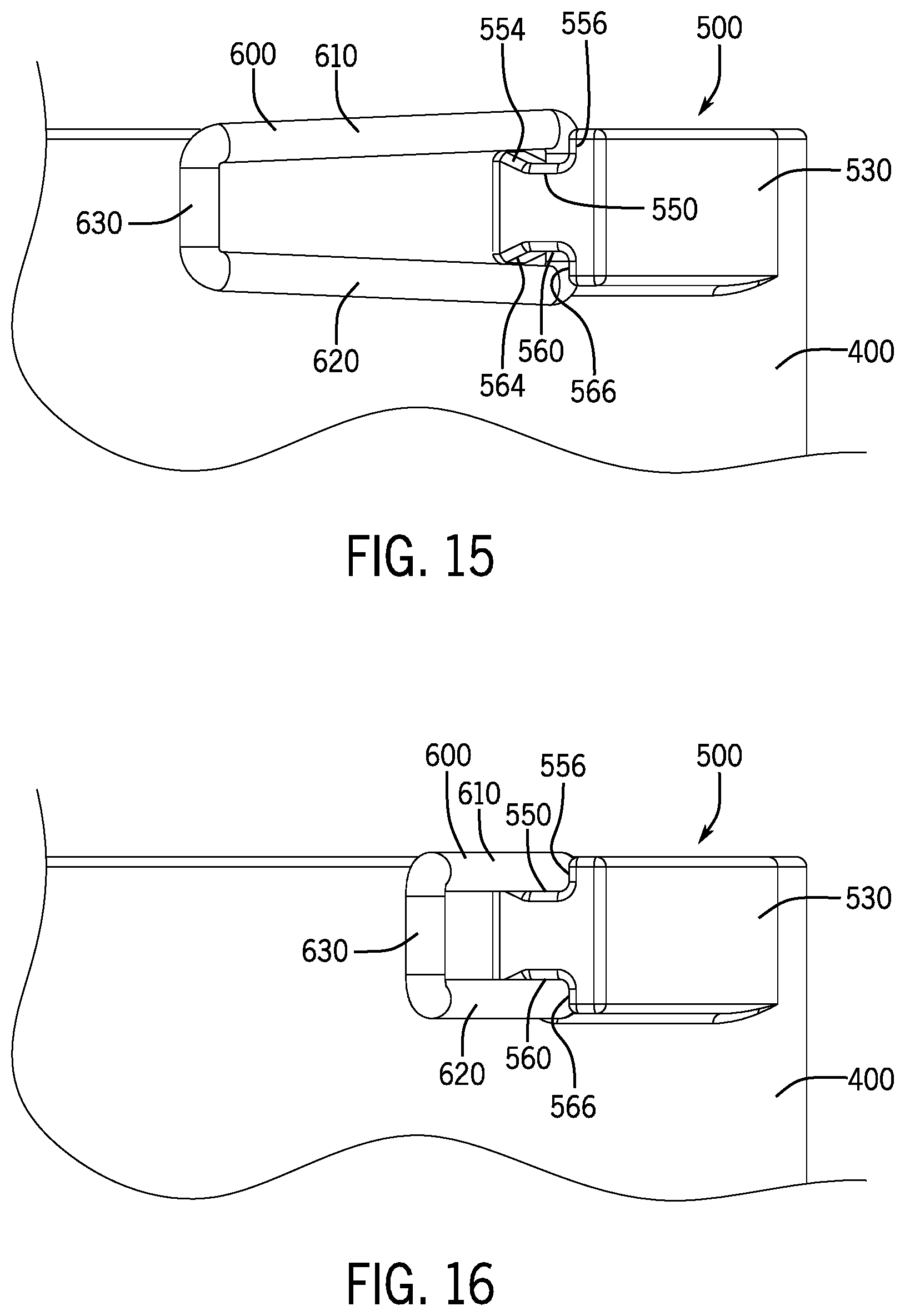
[0023] FIG. 15 is a side view of the second beverage container assembly with the closure moved to the open position and the showing the upper and lower members biasing against the ramp surface.
[0024] FIG. 16 is a side view of the second beverage container assembly with the closure moved to the closed position
DETAILED DESCRIPTION OF INVENTION
[0025] For purposes of this application, any terms that describe relative position (e.g., "upper", "middle" "lower", "outer", "inner", "above", "below", "bottom", "top", etc.) refer to an aspect of the invention as illustrated, but those terms do not limit the orientation in which the embodiments can be used.
[0026] A first beverage container assembly 10 will now be described with reference to FIGS. 1-9. The first beverage container assembly 10 includes a beverage container 50 to hold a beverage and a lid 100 to selectively close the beverage container 50. The lid 100 may engage with the beverage container 50 to form the beverage container assembly 10.
[0027] As shown in FIGS. 1-2, the lid 100 includes the lid body 110. The lid 110 is shaped and configured to close an opening of the beverage container 50. The lid body 110 includes a lower wall 120 that forms an engaging member to removably engage with an engaging member of the beverage container 50. The engaging members may include complementary components of a threaded engagement, snap-fit engagement, frictional engagement, bayonet engagement, or other engagements configured to selectively attach the lid 100 to the beverage container 50. In this aspect, the lid body 110 includes a cap 150 hingedly engaged to the lid body 110 by a hinge portion 155. The cap 150 may open to uncover a drinking conduit 170 such as a drink aperture, spout, nozzle, valve, sprayer, straw, or other fluid passage that is in fluidic communication with an interior of the beverage container 50. Of course, one of ordinary skill in the art will recognize that the lid body 110 may be used with any of variety of beverage containers, drinking vessels, water bottles, tumblers, etc. of all varying types, sizes, and applications. In this aspect, the lid 100 includes the drinking conduit 170 as a spout. Further, one of ordinary skill in the art will recognize that the lid body 110 may omit the cap 150 and still provide the closure features described herein.
[0028] The lid 100 includes a handle 200 with a closure 300, which is pivotally engaged to the handle 200. The closure 300 can be opened to permit attaching the lid 100 (and, when present, the beverage container 50 to a backpack, other bag, fence, etc. Similarly, other objects may be attached to the closure 300 to maintain such objects connected or attached to the beverage container 50. For example, gym cards, wallets, key chains, decorative ornaments, containers, tags, etc. may all be connected to the closure 300 (or slid over the handle 200 when the closure 300 is open).
[0029] The closure 300 is biased to a closed position or under spring tension urging the closure 300 to the closed position. The closure 300 is pivotally engaged to the handle 300 under the bias or spring tension. The closure 300 is configured to pivot or rotate between an open position and the closed position. In order to open the closure 300, the user urges the closure 300 sufficiently to overcome the bias or spring tension and moves the closure 300 to the open position. In a normal state, the closure 300 will generally automatically move to the closed position by the bias or spring tension. Once the user releases the closure 300 and no other force is acting on the closure 300, the closure 300 may spring or snap to the closed position.
[0030] In this aspect, the closure 300 includes an upper member 310 and a lower member 320 that join together in a distal end 330. The distal end 330 is generally opposite of a pivot end 340. The distal end 330 includes a transition portion 308 that joins the upper member 310 and the lower member 320. In this aspect, the upper member 310 and the lower member 320 are generally arranged parallel to each other with a space separating the upper member 310 and the lower member 320. In this aspect, the transition portion 308 is generally perpendicular to the upper member 310 and the lower member 320. The upper member 310 and the lower member 320 may have a generally linear shape. With respect to FIG. 3, opposite of the distal end 330, the upper member 310 angles downward to form a first connection portion 315 and the lower member 320 angles upward to form a second connection portion 325. In this aspect, the first connection portion 315 and the second connection portion 325 are generally perpendicular to the upper member 310 and the lower member 320, respectively. The first connection portion 315 and the second connection portion 325 are at the pivot end 340 of the closure 300.
[0031] In certain aspects, the closure 300 is a single piece construction, while in other aspects, any of the upper member 310, lower member 320, distal end 330, pivot end 340, first connection portion 315, or second connection portion 325 may be a separate unit that gets connected or adhered or pieced together with the other sections of the closure 300. The closure 300 may be formed from any material having sufficient flexibility to function as described.
[0032] With reference to FIGS. 5-7, the closure 300 is pivotally engaged to the handle 200 to pivot between the open position and the closed position. In the open position, an opening 205 is accessible. The opening 205 is between a first handle portion 210 and a second handle portion 230. The opening 205 provides a path to an interior holding portion 240 of the handle 210. For example, when hanging the first beverage container assembly 10 to a chain-link fence, a loop of the fence may pass through the opening 205 and into the interior holding portion 240 of the handle 200.
[0033] In this aspect, the first handle portion 210 forms a gripping structure for the user. The first handle portion 210 extends from the lid body 110 to define a portion of the interior holding portion 240 of the handle 210, which is sized and shaped for the user's hand and for engaging with the fence, bag, keys, etc. Another border of the interior holding portion 240 is formed by the closure 300. The first handle portion 210 further forms a receiving member 215 to hold or engage with the distal end 330 of the closure 300. The closure 300 is pivotally engaged to the second handle portion 230.
[0034] In certain aspects, as shown in FIG. 5, the receiving member 215 includes a hook shape forming a receiving space 220. The distal end 330 of the closure 300 fits into the receiving space 220. In certain aspects, the receiving space 220 includes a linear portion 223 leading into a curved portion 224. Walls 222 of the receiving member 215 may form the linear portion 223 and the curved portion 224. The walls 222 may curve inward toward a central axis of the lid 100 to form the curved portion 224. In FIG. 6, the distal end 330 has moved to the linear portion 223. In FIG. 7, the distal end 330 has moved from the linear portion 223 to the curved portion 224.
[0035] In this aspect, the second handle portion 230 includes an upper opening 232 and a lower opening 242. The first connection portion 315 of the upper member 310 inserts into and pivots in the upper opening 232, while the second connection portion 325 of the lower member 320 inserts into and pivots in the lower opening 242. The upper opening 232 and the lower opening 242 may join together to form a channel completely through the second handle portion 230. In other aspects, the upper opening 232 and the lower opening 242 only pass partially into the second handle portion 230. With reference to FIGS. 3, 4, 8 and 9, the upper opening 232 is in an upper base surface 250 of the second handle portion 230. The upper base surface 250 includes a ramp surface 254. The upper opening 232 is in a generally central stretch of the upper base surface 250 between the ramp surface 254 and an outer upper edge 256. The lower opening 242 is in generally central stretch of a lower base surface 260 of the second handle portion 230. The lower base surface 260 includes an inner wall 264 and an outer lower edge 266. The lower opening 242 is in the lower base surface 260 between the inner wall 264 and the outer lower edge 266.
[0036] In the illustrated aspect, the pivoting engagement of the closure 300 to the second handle portion 230 also assists in forming the bias that urges the closure 300 to the closed position. The second handle portion 230 includes one or more ramps, inclined or wedge surfaces that interact with one or both of the upper member 310 and the lower member 320. In this aspect, the second handle portion 230 includes the ramp surface 254 formed on or part of the upper base surface 250. In other aspects, the ramp surface 254 is formed on or part of the lower base surface 260. In still further aspects, the ramp surface 254 and additional ramp surfaces may be formed on or as part of both the upper base surface 250 and the lower base surface 260.
[0037] As shown in FIG. 8, in this aspect, the ramp surface 254 is adjacent to the upper opening 232 and slopes upward in the direction that the closure 300 moves to in the open position, i.e., the ramp surface 254 slopes upward moving away from the outer upper edge 256 and toward the interior holding portion 240 of the handle 210. In other aspects, the ramp surface 254 may be formed on the lower base surface 260. In still additional aspects, the closure 230 could be configured to move away from the interior holding portion 240, then the ramp surface 254 could slope toward the outer upper edge 256.
[0038] As the closure 300 is urged inward to the open position in the illustrated aspect, a section of the upper member 310 contacts the ramp surface 254 and biases against the ramp surface 254. The upper member 310 and the lower member 320 may flex relative to each other and/or relative to the distal end 330. For example, the space between the upper member 310 and the lower member 320 may increase, thus loading the closure member 300 with tension or a biasing force. As the upper member 310 moves further against the ramp surface 254, the tension or bias may increase. The movement of the closure 300 to the open position may bias or tension the closure member 300 by increasing a distance between the upper member 310 and the lower member 320. When the closure 300 is released by the user, the tension or bias between the upper member 310 and the ramp surface 254 will drive the closure 300 back to the closed position. This provides for an automatic closure of the closure 300 when the user releases the closure 300 when the closure 300 is in the open position.
[0039] As shown in FIG. 6, when the closure 300 is closed and minimal to no force is acting on the handle 200, the distal end 330 of the closure 300 enters the linear portion 223 of the receiving space 220. When the closure 300 is closed, the interior holding portion 240 of the handle 210 is now fully closed, i.e., the opening 205 to the interior holding portion 240 of the handle 210 is closed by the closure 300. As shown in FIG. 7, when a user carries the handle 200 or the handle 200 is attached to a bag, fence, or other article, the weight of the first beverage container assembly 10 weighs down the handle 200, and the distal end 330 of the closure 300 enters the curved portion 224 of the receiving space 220. This provides extra security to prevent inadvertent opening of the closure 300 since the wall of the receiving member 215 arcs to partially enclose the distal end 330. In certain aspects, the receiving space 220 includes the walls of the linear portion 223 transitioning or curving into the curved portion 224.
[0040] In the aspect of FIGS. 1-9, the handle 200 extends generally perpendicular to a central axis of the lid 100. In other aspects, the handle 200 may extend at an angle (positive or negative) to the central axis of the lid 100. In other aspects, the handle 200 may hingedly or pivotally connect with the lid 100. For example, an end of the first handle portion 210 proximate to the lid 100 and an end of the second handle portion 230 proximate to the lid 100 may be hingedly or pivotally connected to the lid 100. For example, an axle may pass through the end of the first handle portion 210 proximate to the lid 100, the end of the second handle portion 230 proximate to the lid 100, and an axle receiving portion of the lid 100.
[0041] In other aspects, the handle 200 may be used with other portable articles that are hung or carried. For example, the first handle portion 210, the second handle portion 230, and the closure 300 may be attached or connected to the exterior or outer surfaces of such portable articles.
[0042] A second beverage container assembly 11 will now be described with reference to FIGS. 10-16. The beverage container assembly 11 includes a beverage container 51 to hold a beverage and a lid 400 to selectively close the beverage container 51.
[0043] The second beverage container assembly 11 generally operates in a similar manner to the first beverage container assembly 10, i.e., a closure member opens against a bias provided by a ramp surface. However, the second beverage container assembly 11 utilizes two ramp surfaces. In the second beverage container assembly 11, a handle portion includes an upper ramp surface and lower ramp surface that bias the closure member.
[0044] The lid 400 may engage with the beverage container 51 to form the beverage container assembly 11. As shown in FIGS. 10-11, the lid 400 includes the lid body 410. The lid 410 is shaped and configured to close an opening of the beverage container 51. The lid body 410 includes a lower wall 420 that forms an engaging member to removably engage with an engaging member of the beverage container 51. The engaging members may include complementary components of a threaded engagement, snap-fit engagement, frictional engagement, bayonet engagement, or other engagements configured to selectively attach the lid 400 to the beverage container 51.
[0045] The lid 400 includes a handle 500 with a closure 600, which is pivotally engaged to the handle 500. The closure 600 can be opened to permit attaching the lid 400 (and, when present, the beverage container 51) to a backpack, other bag, fence, etc.
[0046] The closure 600 is biased to a closed position or under spring tension urging the closure 600 to the closed position. The closure 600 is pivotally engaged to the handle 600 under the bias or spring tension. The closure 600 is configured to pivot or rotate between an open position and the closed position. In order to open the closure 600, the user urges the closure 600 sufficiently to overcome the bias or spring tension and moves the closure 600 to the open position. In a normal state, the closure 600 will generally automatically move to the closed position by the bias or spring tension. Once the user releases the closure 600 and no other force is acting on the closure 600, the closure 600 may spring or snap to the closed position.
[0047] In this aspect, the closure 600 includes an upper member 610 and a lower member 620 that join together in a distal end 630. The distal end 630 is generally opposite of a pivot end 640. In this aspect, the upper member 610 and the lower member 620 are generally arranged parallel to each other with a space separating the upper member 610 and the lower member 620. The upper member 610 and the lower member 620 may have a generally linear shape. With respect to FIG. 11, opposite of the distal end 630, the upper member 610 angles downward to form a first connection portion 615 and the lower member 620 angles upward to form a second connection portion 625. In this aspect, the first connection portion 615 and the second connection portion 625 are generally perpendicular to the upper member 610 and the lower member 620, respectively. The first connection portion 615 and the second connection portion 625 are at the pivot end 640 of the closure 600.
[0048] In certain aspects, the closure 600 is a single piece construction, while in other aspects, any of the upper member 610, lower member 620, distal end 630, pivot end 640, first connection portion 615, or second connection portion 625 may be a separate unit that gets connected or adhered or pieced together with the other sections of the closure 600. The closure 600 may be formed from any material having sufficient flexibility to function as described.
[0049] With reference to FIGS. 12-14, the closure 600 is pivotally engaged to the handle 500 to pivot between the open position and the closed position. In the open position, an opening 505 is accessible. The opening 505 is between a first handle portion 510 and a second handle portion 530. The opening 505 provides a path to an interior holding portion 540 of the handle 510. For example, when hanging the beverage container assembly 11 to a chain-link fence, a loop of the fence may pass through the opening 505 and into the interior holding portion 540 of the handle 500.
[0050] In this aspect, the first handle portion 510 forms a gripping structure for the user. The first handle portion 510 extends from the lid body 410 to define the interior holding portion 540 of the handle 510, which is sized and shaped for the user's hand and for engaging with the fence, bag, etc. The first handle portion 510 further forms a receiving member 515 to hold or engage with the distal end 630 of the closure 600. The closure 600 is pivotally engaged to the second handle portion 530.
[0051] In certain aspects, the receiving member 515 includes a hook shape forming a receiving space 520. The distal end 630 of the closure 600 fits into the receiving space 520. In certain aspects, the receiving space 520 includes a linear portion 522 leading into a curved portion 524. Walls 526 of the receiving member 515 may form the linear portion 522 and the curved portion 524. The walls 526 may curve inward toward a central axis of the lid 400 to form the curved portion 524. In FIG. 13, the distal end 630 has moved to the linear portion 522. In FIG. 14, the distal end 630 has moved from the linear portion 522 to the curved portion 524.
[0052] In this aspect, the second handle portion 530 includes an upper opening 532 and a lower opening 542. The first connection portion 615 of the upper member 610 inserts into and pivots in the upper opening 532, while the second connection portion 625 of the lower member 620 inserts into and pivots in the lower opening 542. The upper opening 532 and the lower opening 542 may join together to form a channel completely through the second handle portion 530. In other aspects, the upper opening 532 and the lower opening 542 only pass partially into the second handle portion 530. With reference to FIGS. 11 and 15, the upper opening 532 is in an upper base surface 550 of the second handle portion 530. The upper base surface 550 transitions into an upper ramp surface 554. The upper opening 532 is in the upper base surface 550 between the upper ramp surface 554 and a front wall 556. The lower opening 542 is in a lower base surface 560 of the second handle portion 530. The lower base surface 560 transitions into a lower ramp surface 564. The lower opening 542 is in the lower base surface 560 between the lower ramp surface 564 and a front wall 566.
[0053] The pivoting engagement of the closure 600 to the second handle portion 530 also assists in forming the bias that urges the closure 600 to the closed position. The second handle portion 530 includes one or more ramps, inclined or wedge surfaces that interact with one or both of the upper member 610 and the lower member 620. As shown in FIG. 15, the upper ramp surface 554 is adjacent to the upper opening 532 and slopes upward in the direction that the closure 600 moves to in the open position, and the lower ramp surface 564 is adjacent to the lower opening 542 and slopes downward in the direction that the closure 600 moves to in the open position. As the closure 600 is urged inward to the open position, the upper member 610 contacts the upper ramp surface 554 and biases against the upper ramp surface 554, while the lower member 620 contacts the lower ramp surface 564 and biases against the lower ramp surface 564. The upper member 610 and the lower member 620 may flex relative to each other and/or relative to the distal end 630. For example, the space between the upper member 610 and the lower member 620 may increase, thus loading the closure member 600 with tension or a biasing force. As the upper member 610 and the lower member 620 move further against the respective ramp surfaces 554 and 564, the tension or bias may increase. The movement of the closure 600 to the open position may bias or tension the closure member 600 by increasing a distance between the upper member 610 and the lower member 620. When the closure 600 is released by the user, the tension or bias between the upper member 610 and the upper ramp surface 554 and the lower member 620 and the lower ramp surface 564 will drive the closure 600 back to the closed position.
[0054] In the aspect of FIGS. 10-16, as the closure 600 pivots to the open position, the upper member 610 contacts the upper ramp surface 254 and biases against the upper ramp surface 554 and the lower member 620 contacts the lower ramp surface 564 and biases against the lower ramp surface 564. In other aspects, a single ramp surface may provide the necessary bias or tension to urge the closure 600 to the closed position. As such, in certain aspects, either the upper ramp surface 554 or the lower ramp surface 564 may be omitted.
[0055] As shown in FIG. 13, when the closure 600 is closed and minimal to no force is acting on the handle 500, the distal end 630 of the closure 600 enters the linear portion 522 of the receiving space 520. When the closure 600 is closed, the interior holding portion 540 of the handle 510 is now fully closed, i.e., the opening 505 to the interior holding portion 540 of the handle 510 is closed by the closure 600. As shown in FIG. 14, when a user carries the handle 500 or the handle 500 is attached to a bag, fence, or other article, the weight of the beverage container assembly 11 weighs down the handle 500, and the distal end 630 of the closure 600 enters the curved portion 524 of the receiving space 520. This provides extra security to prevent inadvertent opening of the closure 600. In certain aspects, the receiving space 520 includes the walls 526 of the linear portion 522 transitioning or curving into the curved portion 524.
[0056] The lid 400 includes a dispensing opening 430 passing through the lid body 410. The dispensing opening 430 may include a nozzle, spout, valve, sprayer, opening or other fluid passage used in beverage containers and drinking apparatus. In certain aspects, a covering may fit over or engage to the lid 400.
[0057] In the aspect of FIGS. 10-16, the handle 500 extends generally perpendicular to a central axis of the lid 400. In other aspects, the handle 500 may extend at an angle (positive or negative) to the central axis of the lid 400. In other aspects, the handle 500 may hingedly or pivotally connect with the lid 400. For example, an end of the first handle portion 510 proximate to the lid 400 and an end of the second handle portion 530 proximate to the lid 400 may be hingedly or pivotally connected to the lid 400. For example, an axle may pass through the end of the first handle portion 510 proximate to the lid 400, the end of the second handle portion 530 proximate to the lid 400, and an axle receiving portion of the lid 400.
[0058] In other aspects, the handles 200 and 500 may be used with other portable articles that are hung or carried. For example, the first handle portions 210, 510, the second handle portions 230, 530, and the closures 300, 600 may be attached or connected to the exterior or outer surfaces of such portable articles.
[0059] In other aspects, the first handle portions 210, 510, the second handle portions 230, 530, and the closures 300, 600 may be integrated, attached or incorporated into walls forming beverage containers or into other members or lid bodies that engage beverage containers. For example, a lid body, such as a cap, a ring or other collar member may include the first handle portions 210, 510, the second handle portions 230, 530, and the closures 300, 600 and fit over or otherwise engage to a beverage container. For example, a screw cap or lid for a beverage container may include the first handle portions 210, 510, the second handle portions 230, 530, and the closures 300, 600. Such lid bodies and caps may or may not have a drinking opening.
[0060] As such, it should be understood that the disclosure is not limited to the particular aspects described herein, but that various changes and modifications may be made without departing from the spirit and scope of this novel concept as defined by the following claims. Further, many other advantages of applicant's disclosure will be apparent to those skilled in the art from the above descriptions and the claims below.
* * * * *
D00000
D00001
D00002
D00003
D00004
D00005
D00006
D00007
D00008
XML
uspto.report is an independent third-party trademark research tool that is not affiliated, endorsed, or sponsored by the United States Patent and Trademark Office (USPTO) or any other governmental organization. The information provided by uspto.report is based on publicly available data at the time of writing and is intended for informational purposes only.
While we strive to provide accurate and up-to-date information, we do not guarantee the accuracy, completeness, reliability, or suitability of the information displayed on this site. The use of this site is at your own risk. Any reliance you place on such information is therefore strictly at your own risk.
All official trademark data, including owner information, should be verified by visiting the official USPTO website at www.uspto.gov. This site is not intended to replace professional legal advice and should not be used as a substitute for consulting with a legal professional who is knowledgeable about trademark law.