Processing Biomass
MEDOFF; Marshall ; et al.
U.S. patent application number 16/661490 was filed with the patent office on 2020-03-05 for processing biomass. The applicant listed for this patent is XYLECO, INC.. Invention is credited to Thomas Craig MASTERMAN, Marshall MEDOFF, Robert PARADIS.
| Application Number | 20200070120 16/661490 |
| Document ID | / |
| Family ID | 50477883 |
| Filed Date | 2020-03-05 |


| United States Patent Application | 20200070120 |
| Kind Code | A1 |
| MEDOFF; Marshall ; et al. | March 5, 2020 |
PROCESSING BIOMASS
Abstract
Methods and systems are described for processing cellulosic and lignocellulosic materials into useful intermediates and products, such as energy and fuels. For example, conveying systems and methods, such as highly efficient vibratory conveyors, are described for the processing of the cellulosic and lignocellulosic materials.
| Inventors: | MEDOFF; Marshall; (Wakefield, MA) ; MASTERMAN; Thomas Craig; (Rockport, MA) ; PARADIS; Robert; (Burlington, MA) | ||||||||||
| Applicant: |
|
||||||||||
|---|---|---|---|---|---|---|---|---|---|---|---|
| Family ID: | 50477883 | ||||||||||
| Appl. No.: | 16/661490 | ||||||||||
| Filed: | October 23, 2019 |
Related U.S. Patent Documents
| Application Number | Filing Date | Patent Number | ||
|---|---|---|---|---|
| 16177669 | Nov 1, 2018 | 10500561 | ||
| 16661490 | ||||
| 15384126 | Dec 19, 2016 | |||
| 16177669 | ||||
| 14242221 | Apr 1, 2014 | 9556496 | ||
| 15384126 | ||||
| PCT/US2013/006428 | Oct 10, 2013 | |||
| 14242221 | ||||
| 61793336 | Mar 15, 2013 | |||
| 61774731 | Mar 8, 2013 | |||
| 61774735 | Mar 8, 2013 | |||
| 61774740 | Mar 8, 2013 | |||
| 61774744 | Mar 8, 2013 | |||
| 61774723 | Mar 8, 2013 | |||
| 61774684 | Mar 8, 2013 | |||
| 61774746 | Mar 8, 2013 | |||
| 61774780 | Mar 8, 2013 | |||
| 61774750 | Mar 8, 2013 | |||
| 61774752 | Mar 8, 2013 | |||
| 61774754 | Mar 8, 2013 | |||
| 61774761 | Mar 8, 2013 | |||
| 61774773 | Mar 8, 2013 | |||
| 61774775 | Mar 8, 2013 | |||
| 61711801 | Oct 10, 2012 | |||
| 61711807 | Oct 10, 2012 | |||
| Current U.S. Class: | 1/1 |
| Current CPC Class: | Y02E 50/16 20130101; C10L 5/442 20130101; Y02E 50/32 20130101; H01J 37/317 20130101; D21B 1/02 20130101; B01J 2219/0869 20130101; H01J 2237/202 20130101; C10L 2290/28 20130101; B01J 2219/1203 20130101; C10B 19/00 20130101; C10L 5/46 20130101; Y02E 50/30 20130101; A61L 2/087 20130101; B01J 19/085 20130101; B01J 19/123 20130101; C10B 53/02 20130101; C08H 8/00 20130101; C10L 2200/0469 20130101; H01J 5/18 20130101; C10G 32/04 20130101; C10L 2290/36 20130101; G21F 3/00 20130101; B65G 27/04 20130101; Y02E 50/17 20130101; B01J 19/12 20130101; C12P 7/10 20130101; B01J 2219/0871 20130101; B01J 2219/0879 20130101; C10G 1/02 20130101; Y02E 50/14 20130101; B01J 19/125 20130101; C10L 2290/52 20130101; G21K 5/04 20130101; H01J 2237/2002 20130101; H01J 37/20 20130101; B01J 2219/12 20130101; C10L 5/445 20130101; C12P 2201/00 20130101; C10L 2290/24 20130101; C13K 13/002 20130101; Y02P 60/877 20151101; H01J 33/04 20130101; Y02P 60/87 20151101; G21K 5/10 20130101; C10L 5/403 20130101; C13K 1/02 20130101; B01J 19/082 20130101; Y02P 20/145 20151101; B01J 19/22 20130101; Y02E 50/10 20130101 |
| International Class: | B01J 19/08 20060101 B01J019/08; C12P 7/10 20060101 C12P007/10; C10L 5/46 20060101 C10L005/46; C10L 5/40 20060101 C10L005/40; H01J 33/04 20060101 H01J033/04; C13K 13/00 20060101 C13K013/00; C13K 1/02 20060101 C13K001/02; B65G 27/04 20060101 B65G027/04; H01J 37/20 20060101 H01J037/20; D21B 1/02 20060101 D21B001/02; H01J 37/317 20060101 H01J037/317; G21F 3/00 20060101 G21F003/00; H01J 5/18 20060101 H01J005/18; G21K 5/10 20060101 G21K005/10; G21K 5/04 20060101 G21K005/04; B01J 19/22 20060101 B01J019/22; B01J 19/12 20060101 B01J019/12; A61L 2/08 20060101 A61L002/08; C10L 5/44 20060101 C10L005/44; C08H 8/00 20060101 C08H008/00; C10B 19/00 20060101 C10B019/00; C10G 1/02 20060101 C10G001/02; C10B 53/02 20060101 C10B053/02; C10G 32/04 20060101 C10G032/04 |
Claims
1. A method comprising: depositing a biomass material, in particulate form, on a trough of a vibratory conveyor; vibrating the vibratory conveyor and cooling the biomass material, while conveying the biomass material; and exposing the biomass material on the vibratory conveyor to ionizing radiation in the form of at least one electron beam through at least one corresponding opening in the conveyor cover.
2. The method of claim 1, wherein cooling the biomass material comprises cooling the trough.
3. The method of claim 1, further comprising comminuting the biomass prior to exposing the biomass to the ionizing radiation.
4. The method of claim 3, wherein comminuting is selected from the group consisting of shearing, chopping, grinding, hammermilling and combinations thereof.
5. The method of claim 3, wherein comminuting produces a biomass material with particles, and more than 80% of the particles have at least one dimension that is less than about 0.25 inches.
6. The method of claim 3, wherein comminuting produces a biomass material with particles, and no more than 5% of the particles are less than 0.03 inches in their greatest dimension.
7. The method of claim 1, wherein the biomass is irradiated with 10 to 200 Mrad of radiation.
8. The method of claim 1, wherein the biomass is exposed to more than one dose of radiation utilizing multiple accelerating heads to expose the biomass to a plurality of scanning electron beams while the biomass is being conveyed on the vibratory conveyor, each scanning electron beam being delivered through a corresponding opening in the cover.
9. The method of claim 1, wherein the biomass material comprises cellulosic or lignocellulosic material.
10. The method of claim 9, wherein the cellulosic or lignocellulosic material comprises a lignocellulosic material selected from the group consisting of wood, paper, paper products, cotton, grasses, grain residues, bagasse, jute, hemp, flax, bamboo, sisal, abaca, corn cobs, corn stover, coconut hair, algae, seaweed, straw, wheat straw and mixtures thereof.
11. The method of claim 1, wherein the vibratory conveyor has a covering that includes an opening through which the electron beam is directed.
12. The method of claim 1, wherein the opening in the cover includes a window foil that allows passage of the ionizing radiation through the window foil and onto the biomass material.
13. The method of claim 1, wherein the biomass material is conveyed at a rate of at least about 1000 lb/hr.
14. The method of claim 1, wherein the spreader comprises a drop spreader.
15. The method of claim 1, wherein the energy of the electron beam is from about 0.3 to 2 MeV.
16. The method of claim 1, wherein the vibratory conveyor conveys the biomass material at an average speed of from about 3 to 100 ft/min.
17. The method of claim 1, wherein the material is deposited using a spreader.
18. The method of claim 17, wherein when it is deposited the biomass material covers only a portion of a width of the trough, and during conveying the biomass material spreads out to cover substantially the entire width of the trough.
19. The method of claim 1, wherein the electron beam is a scanning electron beam
Description
CROSS REFERENCE TO RELATED APPLICATIONS
[0001] This application is a continuation of U.S. patent application Ser. No. 16/177,669, filed Nov. 1, 2018, which is a continuation of U.S. application Ser. No. 15/384,126, filed Dec. 19, 2016, now abandoned, which is a continuation of U.S. application Ser. No. 14/242,221, filed Apr. 1, 2014, now U.S. Pat. No. 9,556,496, issued on Jan. 31, 2017, which is a continuation of PCT/US13/64289 filed Oct. 10, 2013, which claims priority to the following provisional applications: U.S. Ser. No. 61/711,807, filed Oct. 10, 2012; U.S. Ser. No. 61/711,801, filed Oct. 10, 2012; U.S. Ser. No. 61/774,684, filed Mar. 8, 2013; U.S. Ser. No. 61/774,773, filed Mar. 8, 2013; U.S. Ser. No. 61/774,731, filed Mar. 8, 2013; U.S. Ser. No. 61/774,735, filed Mar. 8, 2013; U.S. Ser. No. 61/774,740, filed Mar. 8, 2013; U.S. Ser. No. 61/774,744, filed Mar. 8, 2013; U.S. Ser. No. 61/774,746, filed Mar. 8, 2013; U.S. Ser. No. 61/774,750, filed Mar. 8, 2013; U.S. Ser. No. 61/774,752, filed Mar. 8, 2013; U.S. Ser. No. 61/774,754, filed Mar. 8, 2013; U.S. Ser. No. 61/774,775, filed Mar. 8, 2013; U.S. Ser. No. 61/774,780, filed Mar. 8, 2013; U.S. Ser. No. 61/774,761, filed Mar. 8, 2013; U.S. Ser. No. 61/774,723, filed Mar. 8, 2013; and U.S. Ser. No. 61/793,336, filed Mar. 15, 2013. The entire disclosure of each of these applications are incorporated by reference herein.
BACKGROUND
[0002] As demand for petroleum increases, so too does interest in renewable feedstocks for manufacturing biofuels and biochemicals. The use of lignocellulosic biomass as a feedstock for such manufacturing processes has been studied since the 1970s. Lignocellulosic biomass is attractive because it is abundant, renewable, domestically produced, and does not compete with food industry uses.
[0003] Many potential lignocellulosic feedstocks are available today, including agricultural residues, woody biomass, municipal waste, oilseeds/cakes and sea weeds, to name a few. At present these materials are either used as animal feed, biocompost materials or are burned in a cogeneration facility or are landfilled.
[0004] Lignocellulosic biomass comprises crystalline cellulose fibrils embedded in a hemicellulose matrix, surrounded by lignin. This produces a compact matrix that is difficult to access by enzymes and other chemical, biochemical and biological processes. Cellulosic biomass materials (e.g., biomass material from which the lignin has been removed) is more accessible to enzymes and other conversion processes, but even so, naturally-occurring cellulosic materials often have low yields (relative to theoretical yields) when contacted with hydrolyzing enzymes. Lignocellulosic biomass is even more recalcitrant to enzyme attack. Furthermore, each type of lignocellulosic biomass has its own specific composition of cellulose, hemicellulose and lignin.
[0005] While a number of methods have been tried to extract structural carbohydrates from lignocellulosic biomass, they are either are too expensive, produce too low a yield, leave undesirable chemicals in the resulting product, or simply degrade the sugars.
[0006] Monosaccharides from renewable biomass sources could become the basis of chemical and fuels industries by replacing, supplementing or substituting petroleum and other fossil feedstocks. However, techniques need to be developed that will make these monosaccharides available in large quantities and at acceptable purities and prices.
SUMMARY OF THE INVENTION
[0007] Disclosed are methods and systems for conveying carbohydrate containing materials prior to, during and/or after processing. In particular, methods for conveying the material using one or more vibratory conveyors are disclosed.
[0008] Provided herein are methods of producing a treated biomass material, where the methods include: providing a starting biomass material; conveying the starting biomass material upon a vibratory conveyor; and exposing the starting biomass material to ionizing radiation while the biomass is being conveyed upon the vibratory conveyer; thereby producing a treated biomass material. Optionally, the biomass defines a substantially uniform thickness bed on the conveyor as it is being exposed to the ionizing radiation. The method can further include distributing the biomass material prior to conveying the biomass material upon the vibratory conveyor and exposing the biomass to ionizing radiation.
[0009] Also provided herein is an apparatus for producing a treated biomass material, which includes: an ionizing radiation source; and a vibratory conveying system, wherein the vibratory conveying system is capable of conveying biomass past the ionizing radiation source.
[0010] The apparatus can also include an enclosure surrounding the biomass when it is proximate to the radiation source. The enclosure can include a window foil integrated into a wall of the enclosure, and wherein the window foil is disposed beneath the radiation source and allows passage of the electrons through the window foil and onto the biomass. The apparatus and methods can further include a feeder conveying system upstream from the vibratory conveying system, wherein the feeder conveying system feeds the biomass to the vibratory conveying system upstream of the radiation field. The feeder conveying system can also be a vibratory conveying system. One or both of the conveying systems can convey the biomass at an average speed of 3 to 100 ft/min, at an average speed of 9 to 50 ft/min, or at an average speed of 10 to 25 ft/min.
[0011] The feeder conveying system can be used to distribute the biomass material onto a bed of substantially uniform thickness. For example, seventy-five percent (75%) or more of the biomass material can be at the average bed thickness, or 80%, 85%, 90%, 95% or more of the biomass material can be at the average bed thickness.
[0012] The biomass in the methods and apparatus can be comminuted prior to being exposed to the ionizing radiation. The type of comminution can be selected from the group consisting of: shearing, chopping, grinding, hammermilling or more than one of these. The comminution can produce a starting biomass material with particles, where greater than 80% or 85% of the particles have at least one dimension that is less than about 0.25 inches, where greater than 90% of the particles have at least one dimension that is less than about 0.25 inches, or where greater than 91%, 92%, 93%, 94%, 95%, 96%, 97%, 98% or 99% of the particles have at least one dimension that is less than about 0.25 inches. The comminution can produce a starting biomass where no more than 5% of the particles are less than 0.03 inches in their greatest dimension, where no more than 5% of the particles are less than 0.02 inches in their greatest dimension or where no more than 5% of the particles are less than 0.01 inches in their greatest dimension.
[0013] In the methods and apparatus, the source of the ionizing radiation can be an electron beam, an ion beam, ultraviolet light with a wavelength of between 100 nm and 280 nm, gamma radiation, X-ray radiation or combinations thereof. An electron beam is preferred.
[0014] The biomass can be irradiated with 10 to 200 Mrad of radiation, with 10 to 75 Mrad of radiation, with 10 to 15 Mrad of radiation, with 15 to 50 Mrad of radiation or with 20 to 35 Mrad of radiation. The biomass can be subjected to multiple rounds of irradiation. For example, the biomass can optionally be conveyed multiple times under a beam of ionizing radiation (e.g., 1, 2, 3, 4 or even more times). For, example, each irradiation increasing total dosage of irradiation to the material with optional cooling between irradiations.
[0015] The energy of the electron beam can be between 0.3 and 2 MeV, or between 0.5 and 10 MeV, between 0.8 and 5 MeV, between 0.8 and 3 MeV, between 1 and 3 MeV, and about 1 MeV.
[0016] In some implementations of the methods or apparatus the biomass material is irradiated with an irradiating device with a power output of at least 50 kW (e.g., at least 75 kW, at least 100, at least 125, at least 500 kW).
[0017] In some implementation of the methods or systems, the biomass material is conveyed at a rate of about 1000 to about 8000 lb/hr (e.g., between about 2000 and 5000 lb/hr) using the vibratory conveyors. Optionally the conveyors can be made using structural materials that include steel such as stainless steel (e.g., 304 or 316 L steel). Optionally the conveyors include anti-stick coatings. For example, the conveyor can include a trough made of stainless steel.
[0018] In the methods and apparatus provided herein, the electron beam can be supplied by an electron accelerator equipped with a scanning horn disposed above the conveyor and configured to direct the electron beam onto the biomass upon the vibratory conveyor.
[0019] The biomass material can receive a substantially uniform level of irradiation. The treated biomass material can exhibit a lower level of recalcitrance relative to the starting biomass material.
[0020] The starting biomass material can include a cellulosic or lignocellulosic material, such as wood, paper, paper products, cotton, grasses, grain residues, bagasse, jute, hemp, flax, bamboo, sisal, abaca, corn cobs, corn stover, coconut hair, algae, seaweed, straw, wheat straw or mixtures thereof.
[0021] In the methods and apparatus provided herein, at least a portion of the conveyor can include an enclosure.
[0022] A vibratory conveyor can provide an efficient mode of conveying biomass material under an irradiation source. The oscillating motions in all the possible combinations of x, y and z directions (where x is the direction of conveying, y is transverse to the direction of conveying, and z is in the direction perpendicular to conveying and orthogonal to x and y) for example, in the x direction, in x+z, and/or in x+y+z, provide many advantages while allowing conveying at a constant speed. The method and systems described can also provide an efficient mode of spreading out biomass material (for example, without additional spreading equipment or with fewer burdens on the optional spreading equipment) to an even thickness so that the irradiation can be substantially uniform. A further advantage over some other conveying systems and methods is that the biomass is turned and rotated, improving the irradiation uniformity, dosage averaging and cooling of the biomass. The uniform irradiation and improved dosage averaging can provide a material that has reduced recalcitrance throughout its bulk. Also, vibratory conveyors, for example, in comparison to other conveying systems and methods, can be lower in cost to operate. The methods and systems described herein can also reduce the intensity of irradiation needed to irradiate through the bulk of a biomass and reduce costs and increase safety of used, e.g., by reducing the shielding that is required.
[0023] Implementations of the invention can optionally include one or more of the following summarized features. In some implementations, the selected features can be applied or utilized in any order while in others implementations a specific selected sequence is applied or utilized. Individual features can be applied or utilized more than once in any sequence. In addition, an entire sequence, or a portion of a sequence, of applied or utilized features can be applied or utilized once or repeatedly in any order. In some optional implementations, the features can be applied or utilized with different, or where applicable the same, set or varied, quantitative or qualitative parameters as determined by a person skilled in the art. For example, parameters of the features such as size, individual dimensions (e.g., length, width, height), location of, degree (e.g., to what extent such as the degree of recalcitrance), duration, frequency of use, density, concentration, intensity and speed can be varied or set, where applicable as determined by a person of skill in the art.
[0024] Features, for example, include: a method for exposing a biomass material to ionizing radiation while the biomass material is being conveyed upon a vibratory conveyor; the biomass material defines a substantially uniform thickness bed on the conveyor as it is being exposed to the ionizing radiation; distributing the biomass material prior to conveying the biomass material upon the vibratory conveyer and exposing the biomass to the ionizing radiation; distributing the biomass material utilizes a feeder conveying system; the feeder conveying system comprises a second vibratory conveying system; seventy five percent or more of the biomass material is distributed to be at the level of the average bed thickness; eighty five percent or more of the biomass material is distributed to be at the level of the average bed thickness; ninety percent or more of the biomass material is distributed to be at the level of the average bed thickness; ninety five percent or more of the biomass material is distributed to be at the level of the average bed thickness; comminuting the biomass prior to exposing the biomass to the ionizing radiation; comminuting consists of shearing; comminuting consists chopping; comminuting consists of grinding; comminuting consists of hammermilling; comminuting produces a biomass material with particles; comminuting produces a biomass material wherein greater than 80% of the particles have at least one dimension that is less than about 0.25 inches; comminuting produces a biomass material wherein greater than 90% of the particles have at least one dimension that is less than about 0.25 inches; comminuting produces a biomass material wherein greater than 95% of the particles have at least one dimension that is less than about 0.25 inches; comminuting produces a biomass material wherein no more than 5% of the particles are less than 0.03 inches in their greatest dimension; the source of the ionizing is an electron beam; the source of the ionizing is an ion beam; the source of the ionizing is ultraviolet light with a wavelength of between 100 nm and 280 nm; the source of the ionizing is gamma radiation; The source of the ionizing is X-ray radiation; the biomass is irradiated with 10 to 200 Mrad of radiation; the biomass is irradiated with 10 to 25 Mrad of radiation; the biomass is irradiated with 10 to 75 Mrad of radiation; the biomass is irradiated with 15 to 50 Mrad of radiation; the biomass is irradiated with 20 to 35 Mrad of radiation; the energy of the electron beam is between 0.3 and 2 MeV; the electron beam is supplied by an electron accelerator equipped with a scanning horn disposed above the conveyor and configured to direct the electron beam onto the biomass upon the vibratory conveyor; the biomass material receives a substantially uniform level of ionizing radiation; the biomass material comprises a cellulosic or lignocellulosic material; The biomass material includes wood; The biomass material includes paper; the biomass material includes wood paper products; the biomass material includes cotton; the biomass material includes grasses; the biomass material includes grain residues; the biomass material includes bagasse; the biomass material includes jute; the biomass material includes hemp; the biomass material includes flax; the biomass material includes bamboo; the biomass material includes sisal; the biomass material includes abaca; the biomass material includes corn cobs; the biomass material includes corn stover; the biomass material includes coconut hair; the biomass material includes algae; the biomass material includes seaweed; the biomass material includes straw; the biomass material includes wheat straw; at least a portion of the conveyor comprises an enclosure; exposing the biomass material to ionizing radiation reduces the recalcitrance of the biomass material; the vibratory conveyer conveys the biomass material at an average speed of 3 to 100 ft/min; the vibratory conveyer conveys the biomass material at an average speed of 9 to 50 ft/min; the vibratory conveyer conveys the biomass material at an average speed of 12 to 25 ft/min; the biomass material is irradiated with an irradiator with a power output of at least 50 kW; the biomass material is conveyed at a rate of about 1000 to about 8000 lb/hr: the biomass is exposed to ionizing radiation more than one time.
[0025] Some other features, for example, include: an apparatus for producing a treated biomass material including an ionizing radiation source and a vibratory conveyor system, wherein the vibratory conveyor system is capable of conveying biomass material past the ionizing radiation source; an enclosure surrounding the biomass material when the biomass material is proximate to a radiation source; the enclosure comprises a window foil integrated into a wall of the enclosure, and wherein the window foil is disposed beneath the radiation source and allows passage of the electrons through the window foil and onto the biomass material; a feeder conveying system upstream from the vibratory conveying system, wherein the feeder conveying system is configured to spread the biomass material to form a bed of biomass material of substantially uniform depth, and where the feeder conveying system feeds the biomass material to the vibratory conveying system upstream of the radiation field; the feeder conveying system is a vibratory conveying system; the conveyor system comprises structural materials including steel.
[0026] Other features and advantages will be apparent from the following detailed description, and from the claims.
BRIEF DESCRIPTION OF THE DRAWINGS
[0027] FIG. 1A is a side view of a system for treating a biomass. FIG. 1B is a top view of a system for treating a biomass. FIG. 1C is a detailed view of an irradiation zone. FIG. 1D is a right side view of a system for treating a biomass. FIG. 1E is a front side detail view of a window system of a system for treating biomass.
[0028] FIG. 2 is a flow diagram illustrating conversion of a biomass feedstock to one or more products.
[0029] FIG. 3A is a diagram illustrating, by exaggeration, the movement of a particulate biomass on a first type of vibratory conveyor. FIG. 3B is a diagram illustrating, by exaggeration, the movement of a particulate biomass on a second type of vibratory conveyor. FIG. 3C is a diagram illustrating, by exaggeration, the movement of a particulate biomass on a third type of vibratory conveyor.
[0030] FIG. 4 is a perspective view of a vibratory conveyor.
[0031] FIG. 5 is a perspective view of a vibratory conveyor with a cover.
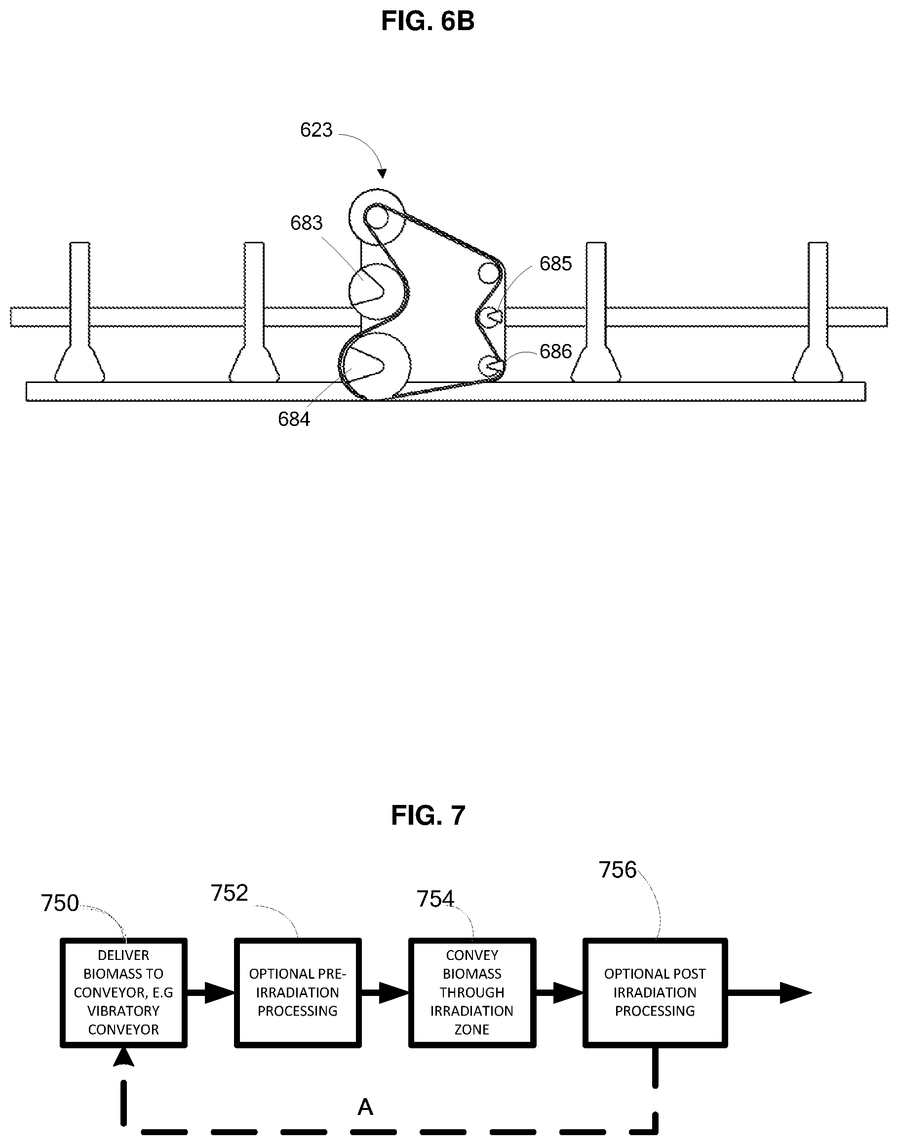
[0032] FIG. 6A is a perspective view of a vibratory conveyor. FIG. 6B is a side view of a vibratory conveyor.
[0033] FIG. 7 is a flow diagram showing a process for treating biomass.
DETAILED DESCRIPTION
[0034] Provided herein are methods and apparatus for producing a treated biomass material with a vibratory conveyer. The methods and apparatus provide an advantage because the vibratory conveyor provides an efficient mode of conveying biomass material while it is under an irradiation source.
[0035] An exemplary embodiment is shown in FIGS. 1A-1E. FIG. 1A shows a front side view of a system for irradiation of particulate biomass. A spreader, for example, a distributer such as a CHRISTY SPREADER.TM. 110 containing a biomass drops a controlled stream of biomass 112 onto the trough of a covered vibratory conveyor 113 through an opening 114 in the cover of the conveyor. This aids in providing a substantially uniform thickness of the material spread across the conveyer. The covered vibratory conveyor is supported by a support 184 and includes a transverse vibration system including leaf springs. The transverse drive assembly 186 provides horizontal oscillating movement to the trough. The drive motor includes an eccentric crank 198. The biomass is conveyed in the direction of the shown arrows (downstream to upstream) through a scanning electron beam 116 generated by an electron beam irradiation device with an accelerating tube 118 and a scanning horn 120. The electron beam is extracted from the high vacuum side of the scan horn through a window foil, passes through an air gap, through a window mounted in the cover 115, and irradiates the material 178 being conveyed beneath. The irradiated material is then conveyed away from the irradiation area and drops into a collecting hopper 122. In preferred embodiments at least the irradiation zone (e.g., the region where the irradiation takes place) is in a vault, and optionally the entire vibratory conveyor and hoppers, for example, as outlined by the dotted line in FIG. 1A 192, can be in a vault. The biomass can enter via ingress 188 and egress 190 respectively.
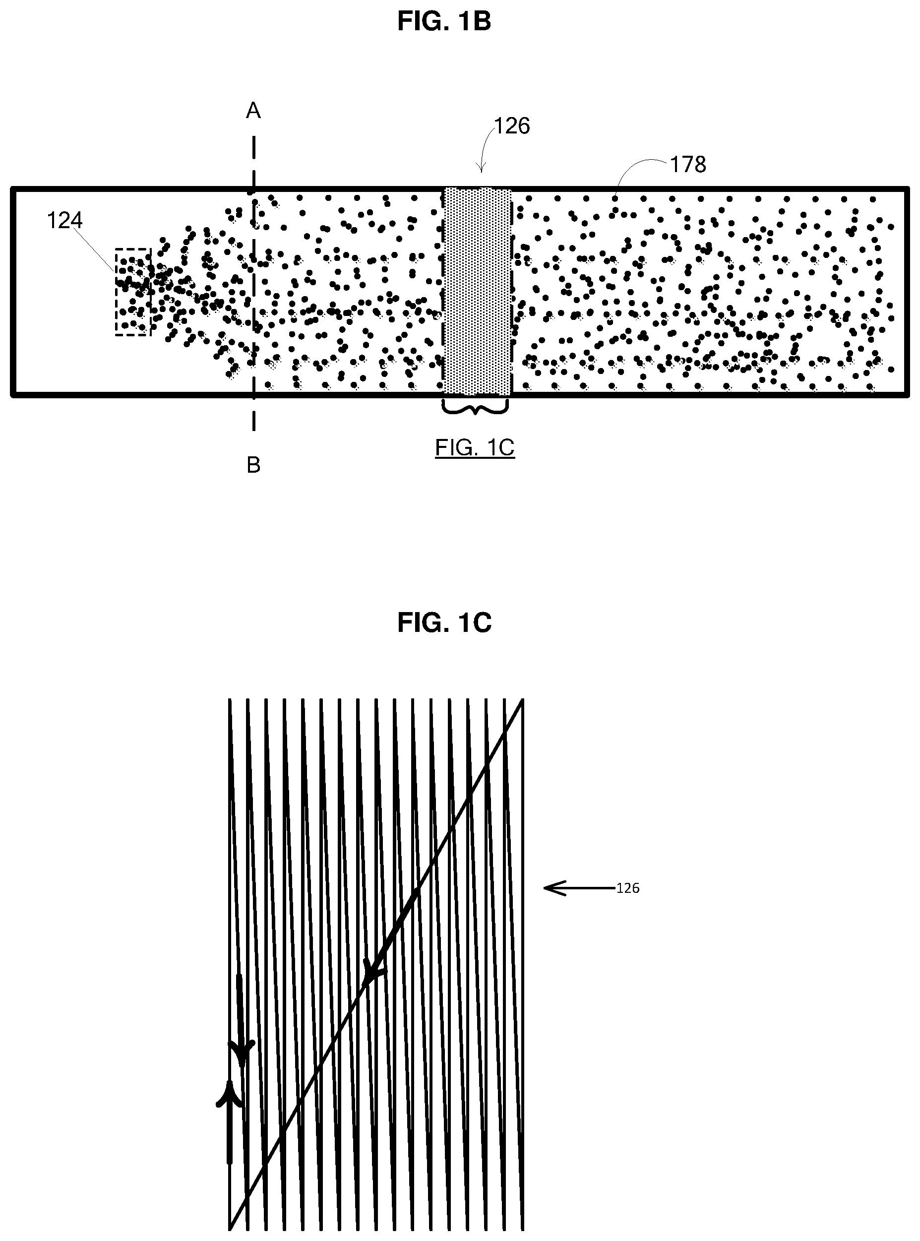
[0036] In the embodiment above, as shown schematically as a top view of the conveyor surface by FIG. 1B, the area covered by the biomass below the opening of the hopper 124 is a small approximately rectangular area compared to the width of the trough, its size being primarily determined by the size and shape of the spreader opening and the vertical drop from the opening of the hopper to the trough surface. In some embodiments the opening width of the spreader is about the same as the width of the conveyor or it can be smaller than the width of the conveyor (e.g., smaller than the conveyor by at least about 1%, smaller than the conveyor by at least about 5%, smaller than the conveyor by at least about 10%, smaller than the conveyor by at least about 15%, smaller than the conveyor by at least about 20%, smaller than the conveyor by at least about 25%). As the biomass is conveyed in the direction indicated by the arrows, the biomass is spread out over the entire width of the trough so that at about the dashed line defined by AB and areas downstream of this line, the biomass covers the entire width of the trough. Additionally to this spreading, the biomass forms a layer of substantially uniform thickness on the conveyor as the material moves down the conveyor. At some distance from line AB, the electron beam impinges on and through the biomass layer. The electron beam is raster scanned over an area 126, the radiation area (zone, field, electron shower). A detailed view of the raster scan area is shown as FIG. 1C. The path of the raster (e.g., a locus of scanned electron beams) is shown projected on the surface of irradiated material wherein the arrows show the path of the raster scan. In other embodiments, the hopper opening is approximately commensurate in size with the trough so that the area 124 spans the entire width of the trough.
[0037] FIG. 1D shows a right side cut out view of a system for irradiating biomass. As shown, the biomass particles 178 form a uniform layer 150 as they are conveyed through the electron beam 116 with minimal up and down motion of the particles. The electron beam is extracted out of the high vacuum side of the scan horn 120 through the scan horn window 174 and then through a window 115 mounted to the cover of the conveyor 113. The tumbling and changing orientation of biomass particles, the even spreading of the biomass along the whole width of the trough as previously discussed, and the raster scan of the e-beam ensures a substantially uniform irradiation of the biomass as it moves down the conveyor through the electron beam shower. The movement of the biomass can also help in cooling (e.g., air cooling) of the biomass.
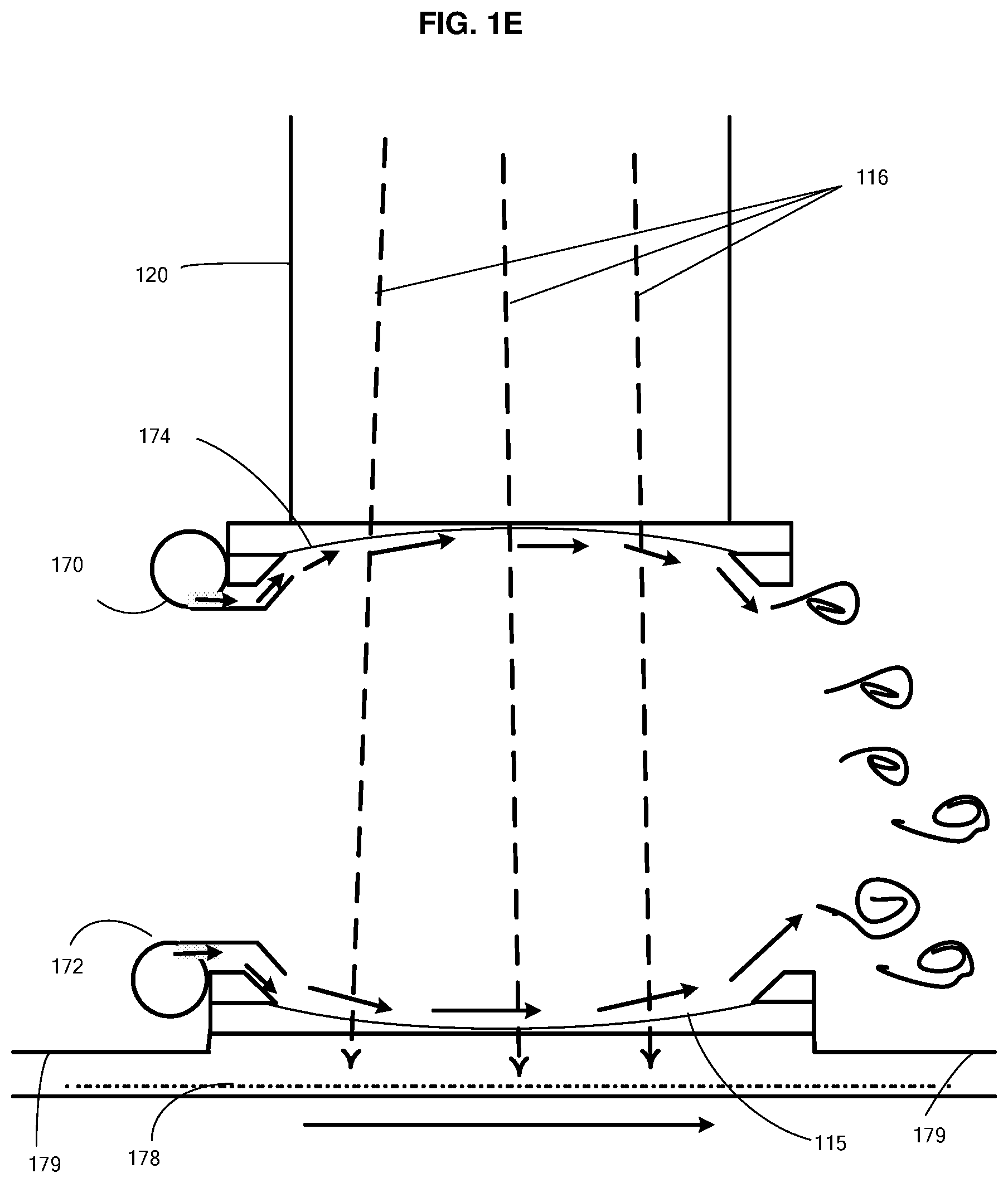
[0038] FIG. 1E shows a cross sectional detailed view of the scan horn and window mounted in the cover. The scan horn includes horn window cooler 170 and the conveyor includes enclosure window cooler 172 to blow air at high velocity across the windows as indicted by the small arrows. The electrons in the electron beam 116 pass through the high vacuum of the scan horn 120 through the scan horn window 174, through the cooling air gap between the scan horn window and enclosure window, through the enclosure window 115 and impinge on and penetrate through the biomass material 178 on the conveyor surface. The scan horn window is curved towards the vacuum side of the scan horn, for example, due to the vacuum. The enclosure window is shown curved towards the conveyed material. The curvature of the windows can help the cooling air path flow past the window for efficient cooling. The enclosure window is mounted on the cover 179 of the enclosed conveyor.
[0039] Biomass can be manufactured into various products by the methods described herein, for example, by reference to FIG. 2, showing a process for manufacturing an alcohol can include, for example, optionally mechanically treating a feedstock 210. Such treatment can make the feedstock easier to convey, for example, on with vibratory conveyor and/or pneumatic conveyor. Before and/or after this treatment, the feedstock can be treated with another physical treatment, for example, irradiation while conveying on a vibratory conveyor as described herein, to reduce or further reduce its recalcitrance 212, and saccharifying the feedstock, to form a sugar solution 214. Optionally, the method may also include transporting, e.g., by pipeline, railcar, truck or barge, the solution (or the feedstock, enzyme and water, if saccharification is performed en route) to a manufacturing plant 216. In some cases the saccharified feedstock is further bioprocessed (e.g., fermented) to produce a desired product 218 and byproduct 211. The resulting product may in some implementations be processed further, e.g., by distillation 220. If desired, the steps of measuring lignin content 222 and setting or adjusting process parameters based on this measurement 224 can be performed at various stages of the process, as described in U.S. patent application Ser. No. 12/704,519, filed on Feb. 11, 2010, the entire disclosure of which is incorporated herein by reference.
[0040] Vibratory conveyors work by the principle of applying an oscillating force or vibration to a material to be conveyed, and particularly to the trough of a conveyor onto which the material to be conveyed is placed. The oscillating force can be supplied by a driver assembly that is mechanically coupled to the trough, as well as elastic elements also mechanically coupled to the trough e.g., springs, leaf spring and/or coil spring. The vibrations can be, for example, supplied by the driver assembly that can include one or more of the drive motors coupled to one or more eccentric cranks or eccentric fly wheels. In some embodiments the vibratory conveyors are natural frequency vibrating conveyors based on obtaining a common frequency between the elastic elements and the drive assembly, for example, as disclosed in U.S. Pat. No. 4,813,532 filed Jan. 15, 1988 and published Mar. 21, 1989, the entire disclosure of which is incorporated herein by reference.
[0041] The driver assembly, elastic elements and coupling to the trough can provide motion to the surface of the trough, on which the feedstock to be conveyed is placed. The motions include all combined directions and magnitudes of x, y and z vectors, where x is the direction of conveying biomass, y is the direction transverse to conveying and z is the direction perpendicular to and orthogonal to the x and y vectors. The displacement distance of the trough can be varied for optimal performance. For example, displacement in the x direction is between about 1/16 inch and 12 inch (e.g., between about 1/16 inch and 8 inch, between about 1/16 inch and 4 inch, between about 1/16 inch and 1 inch, between about 1/8 inch and 12 inch, between about 1/8 inch and 6 inch, between about 1/8 inch and 2 inch, between about 1/8 inch and 1 inch, between about 1/4 inch and 6 inch, between about 1/4 inch and 4 inch, between about 1/4 inch and 2 inch, between about 1/4 inch and 1 inch, between about 1/2 inch and 6 inch, between about 1/2 inch and 4 inch, between about 1/2 inch and 2 inch, between about 1/2 inch and 1 inch, between about 1 inch and 6 inch, between about 1 inch and 4 inch). Displacement in the z direction can be, for example, be between about 0 and 3 inch (e.g., between about 0.004 inch and 3 inch, between about 0.008 inch and 3 inch, between about 0.016 inch and 3 inch, between about 0.025 inch and 3 inch, between about 0.05 inch and 3 inch, between about 0.1 inch and 3 inch, between about 1/4 inch and 3 inch, between about 1/2 inch and 3 inch, between about 1 inch and 3 inch, between about 0.008 Inch and 1 inch, between about 0.016 inch and 1 inch, between about 0.025 inch and 1 inch, between about 0.05 inch and 1 inch, between about 0.1 inch and 1 inch, between about 1/4 inch and 1 inch, between about 1/2 inch and 1 inch, between about 1/16 inch and 3/4 inch, between about 1/8 inch and 3/4 inch, between about 1/4 inch and 3/4 inch, between about 1/2 inch and 3/4 inch). For example, the displacement in the x direction can be greater than the displacement in the z direction by a ratio less than about 3000:1 (e.g., less than about 1000 to 1, less than about 500 to 1, less than about 100 to 1, less than about 50 to 1, less than about 10 to 1, less than about 5:1, less than about 2:1). The displacement in they direction can be less than 1 inch (e.g., less than about 0.5 inch, less than about 0.1 inch, less than about 0.05 inch, less than about 0.005 inch, or even about 0). The frequency of the oscillations can be between 1 and 60 kHz. For example, the frequency can be between about 1 and 100 Hz (e.g., between about 10 and 100 Hz, between about 20 and 100 Hz, between about 40 and 100 Hz, between about 60 and 100 Hz, between about 10 and 80 Hz, between about 20 and 80 Hz, between about 40 and 80 Hz, between about 60 and 80 Hz, between about 20 and 60 Hz). The frequency of oscillation can be higher. For example, the frequency of oscillation can be between about 100 Hz and 20 kHz (e.g., between about 100 Hz and 15 kHz, between about 100 Hz and 10 kHz, between about 100 Hz and 5 kHz, between about 500 Hz and 20 kHz, between about 500 Hz and 15 kHz, between about 500 Hz and 10 kHz, between about 500 Hz and 5 kHz, between about 1 and 20 kHz, between about 1 and 15 kHz, between about 1 and 10 kHz, between about 1 and 5 kHz). The frequency can be even much higher, for example, in the ultrasonic range (e.g., between about 20 and 60 kHz, between about 30 and 60 kHz, between about 40 and 60 kHz, between about 50 and 60 kHz, between about 20 and 50 kHz, between about 30 and 50 kHz, between about 40 and 50 kHz, between about 20 and 40 kHz, between about 30 and 40 kHz, between about 20 and 30 kHz).
[0042] There are at least three types of vibratory conveyors e.g., that can be utilized in the methods herein described. Combinations of these and alternatives can be designed. The three types of conveyors are discussed below.
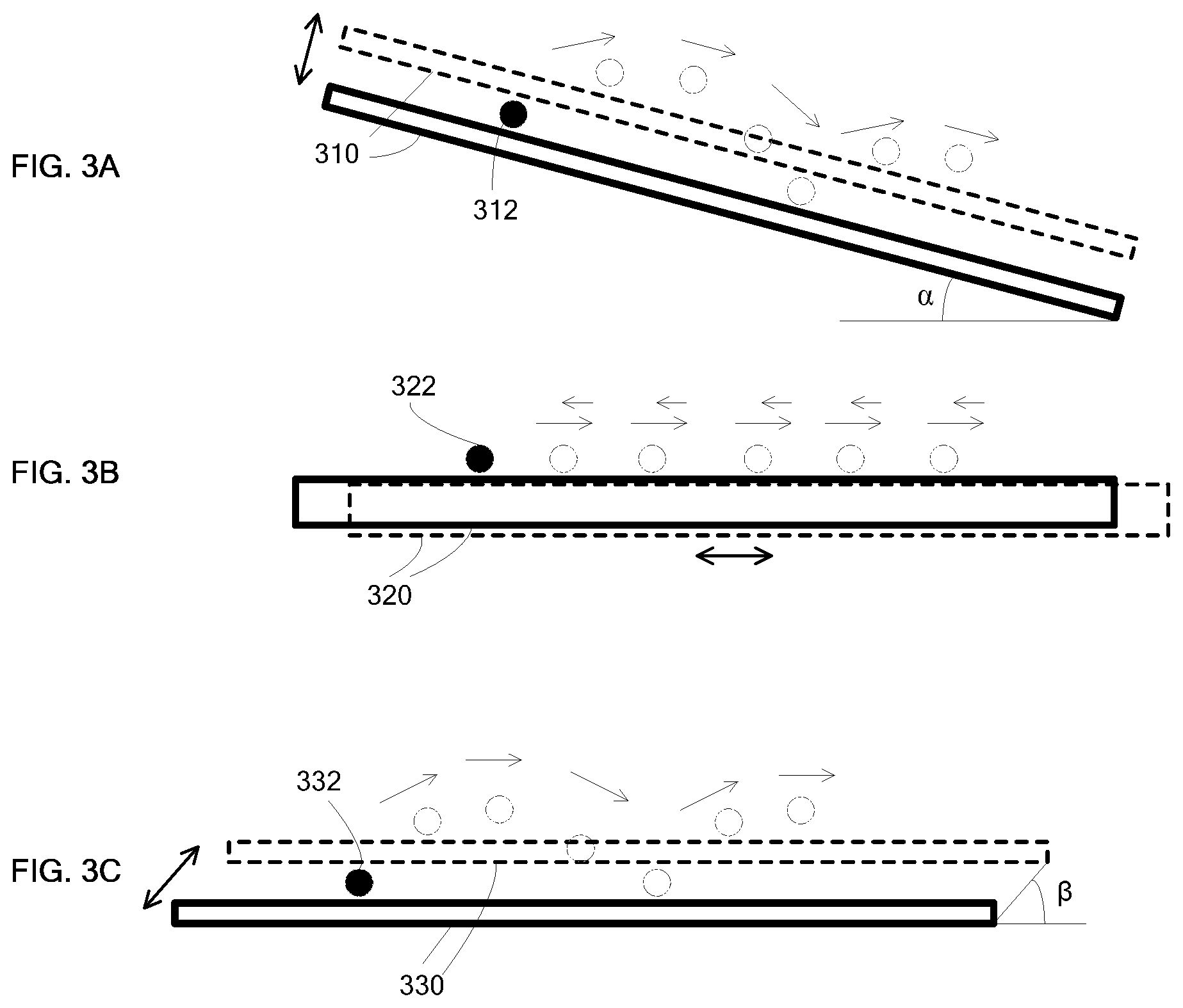
[0043] In one type of vibratory conveyor, as depicted in FIG. 3A, a vertical force is applied to the trough 310 and the trough is inclined at an angle .alpha. (alpha) to the horizontal, for example, at least 1.degree. (arc degree) e.g., at least 5.degree., at least 10.degree., at least 20.degree.). In another configuration the trough is formed into a downwards series of steps (not shown) with a downward incline of at least 1.degree. (e.g., at least 5.degree., at least 10.degree., at least 20.degree., at least 30.degree., at least 40.degree., at least 50.degree., at least 60.degree.). A material, for example, shown as a particle 312 moves sequentially to positions, shown as open circles, the direction of movement shown by arrows. This movement occurs because an oscillatory force or vibrational force is applied perpendicular to the trough surface as shown by the two headed arrows. The oscillatory force repeatedly lofts the material to be conveyed perpendicular to the trough while gravity acts on the material to move it down the incline, or alternatively the steps, of the trough.
[0044] In a second type of vibratory conveyor, depicted in FIG. 3B, the materials to be conveyed are placed on a trough 320 and a purely horizontal force, indicated by the two headed arrow, causes a horizontal movement of the materials. The force is an oscillating force such that the maximum horizontal vibratory forces applied to the trough in the direction of conveyance is less than the static friction force acting between the trough and the material, while the forces applied to the material in the direction opposite to conveyance is higher than the static friction. In this way adherence is maintained between the material and the trough in the direction of conveyance but not in the direction opposite conveyance and the material is conveyed forward in a shuffling manner. A material, for example, shown as particle 322 moves sequentially to positions, shown as open circles, the shuffling movement indicated by the single headed arrows. As well as horizontal and downwards conveying, these types of conveyors can convey materials in upwards direction of up to about 25 degrees.
[0045] In a third type of vibratory conveyor, depicted by FIG. 3C, the material carrying trough 330 is vibrated, as shown by the two headed arrows, at an angle .beta. (beta) to the horizontal, for example, 45 degrees. The material is lofted upwards and in the horizontal direction of incline. Therefore, the material is conveyed forward in a bouncing manner as depicted by the particle 332 the movement indicated by the single headed arrows. As well as horizontal and downwards, these vibratory conveyors can convey materials upwards as well as downwards, for example, at an upwards direction of up to about 25 degrees.
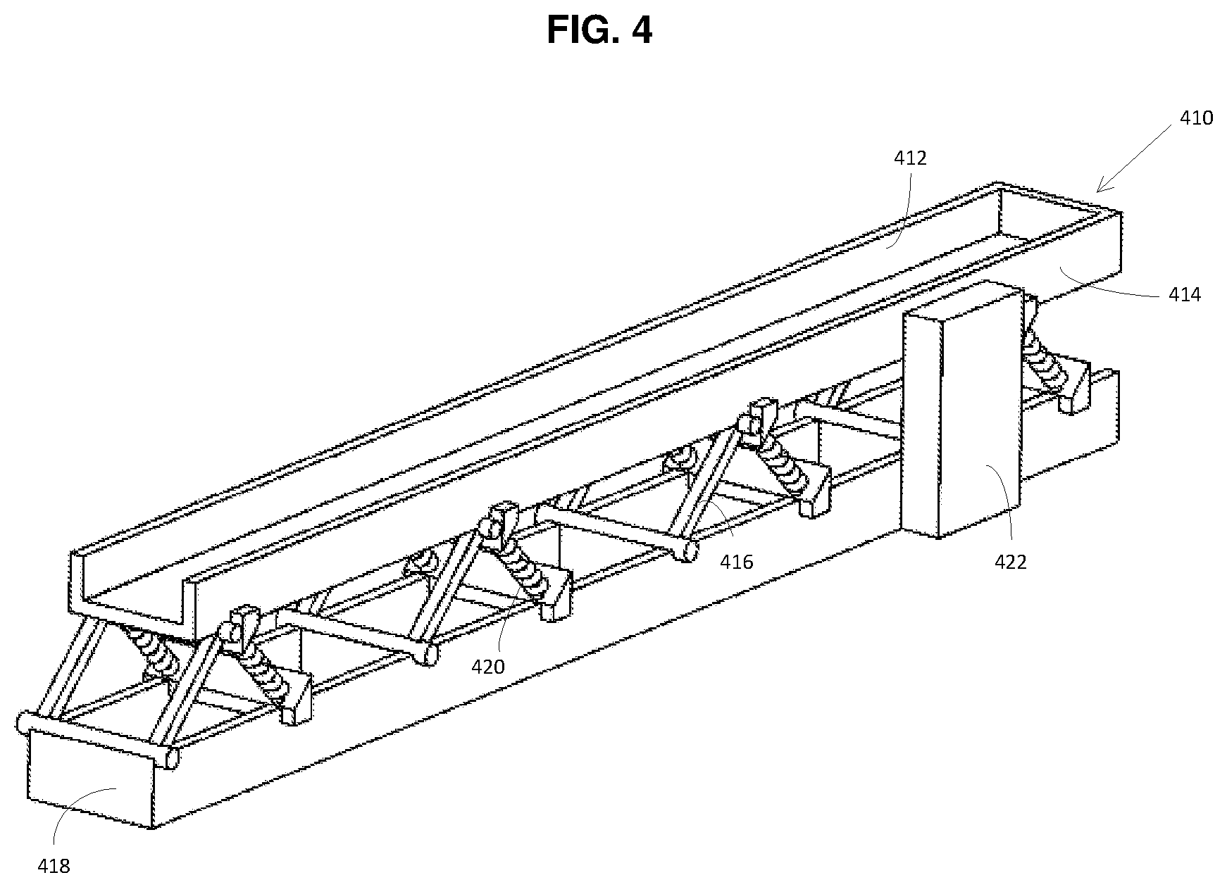
[0046] FIG. 4 is a perspective view of a vibratory conveyor of the third type described above. The trough 410 has side walls 412 and 414 and is supported by support arms, legs or structures 416 that are pivotally connected to the trough on one end and pivotally connected to a base support 418 on the other end. Coil springs are 420 shown at a 45.degree. to the trough and support oscillations at this angle of the trough. A drive assembly 422 coupled to the trough provides the force for the oscillatory motion. Many other configurations of vibratory conveyors are known. For example, instead of coil springs, leaf springs can be used.
[0047] FIG. 5 shows a perspective view of another example of a vibratory conveyor of the third type. This example of a vibratory conveyor includes a drive assembly 510, leaf springs 520, a trough 530, cover 540 and access ports 550. Covers for the conveyors can be added to mitigate, for example, dust generation.
[0048] FIG. 6A shows a perspective view of a vibratory conveyor of the second type 610. The trough 612 carries biomass that has been delivered to the conveyor 630. At the upstream end of the conveyor where the biomass is delivered, e.g., near 630, the biomass may form a pile with a peak. Downstream, e.g., near 640 the biomass is more uniformly spread. The trough is supported by support structures 616 which have pairs of longitudinally spaced vertical legs 617, each pair of legs are connected by horizontal cross members 618 and longitudinal base members 619. The trough 612 is suspended from the overhead structures 616 by vertical straps 621. The straps 621 are attached at one end to the horizontal cross members 618 and at the other end to trough support members 622. The straps 621 are constructed of a dimension in the direction transverse to the path of conveyance much larger than that of the direction parallel to the path of conveyance, and therefore the vertical straps 621 can act as resilient leaf-springs permitting displacement of the trough only in the direction of conveyance. The horizontal deflection of the bottoms of the straps 621 combine with the forces imparted by a vibration generating apparatus 623 creating motion of the trough 612 in substantially horizontal direction with very little vertical deflection. The vibration generating apparatus 623 can, for example, include an eccentric fly wheels 683, 684, 685 and 686 as shown in front side view FIG. 6B. U.S. Pat. No. 5,131,525 (pub. Jul. 21, 1992) describes vibratory conveyors, the entire disclosure thereof incorporated herein by reference.
[0049] The vibratory conveyors described can include screens used for sieving and sorting materials. Port openings on the side or bottom of the troughs can be used for sorting, selecting or removing specific materials, for example, by size or shape. Some conveyors have counterbalances to reduce the dynamic forces on the support structure. Some vibratory conveyors are configured as spiral elevators, are designed to curve around surfaces and/or are designed to drop material from one conveyor to another (e.g., in a step, cascade or as a series of steps or a stair). Along with conveying materials conveyors can be used, by themselves or coupled with other equipment or systems, for screening, separating, sorting, classifying, distributing, sizing, inspection, picking, metal removing, freezing, blending, mixing, orienting, heating, cooking, drying, dewatering, cleaning, washing, leaching, quenching, coating, de-dusting and/or feeding. The conveyors can also include covers (e.g., dust-tight covers), side discharge gates, bottom discharge gates, special liners (e.g., anti-stick, stainless steel, rubber, custom steal, and or grooved), divided troughs, quench pools, screens, perforated plates, detectors (e.g., metal detectors), high temperature designs, food grade designs, heaters, dryers and or coolers. In addition, the trough can be of various shapes, for example, flat bottomed, vee shaped bottom, flanged at the top, curved bottom, flat with ridges in any direction, tubular, half pipe, covered or any combinations of these. In particular, the conveyors can be coupled with an irradiation systems and/or equipment.
[0050] The conveyors (e.g., vibratory conveyor) can be made of corrosion resistant materials. The conveyors can utilize structural materials that include stainless steel (e.g., 304, 316 stainless steel, HASTELLOY.RTM. ALLOYS and INCONEL.RTM. Alloys). For example, HASTELLOY.RTM. Corrosion-Resistant alloys from Hynes (Kokomo, Ind., USA) such as HASTELLOY.RTM. B-3.RTM. ALLOY, HASTELLOY.RTM. HYBRID-BC1.RTM. ALLOY, HASTELLOY.RTM. C-4 ALLOY, HASTELLOY.RTM. C-22.RTM. ALLOY, HASTELLOY.RTM. C-22HS.RTM. ALLOY, HASTELLOY.RTM. C-276 ALLOY, HASTELLOY.RTM. C-2000.RTM. ALLOY, HASTELLOY.RTM. G-30.RTM. ALLOY, HASTELLOY.RTM. G-35.RTM. ALLOY, HASTELLOY.RTM. N ALLOY and HASTELLOY.RTM. ULTIMET.RTM. alloy.
[0051] The vibratory conveyors can include non-stick release coatings, for example, TUFFLON.TM. (DuPont, Delaware, USA). The vibratory conveyors can also include corrosion resistant coatings. For example, coatings that can be supplied from Metal Coatings Corp (Houston, Tex., USA) and others such as Fluoropolymer, XYLAN.RTM., Molybdenum Disulfide, Epoxy Phenolic, Phosphate-ferrous metal coating, Polyurethane-high gloss topcoat for epoxy, inorganic zinc, Poly Tetrafluoro ethylene, PPS/RYTON.RTM., fluorinated ethylene propylene, PVDF/DYKOR.RTM., ECTFE/HALAR.RTM. and Ceramic Epoxy Coating. The coatings can improve resistance to process gases (e.g., ozone), chemical corrosion, pitting corrosion, galling corrosion and oxidation.
[0052] In one embodiment, the conveyors include a cover. These enclosed conveyors are useful, for example, for the mitigation of dust generation. In some embodiments of these enclosed conveyors, a window that is transparent to the electron beam is mounted onto the cover, for example, forming an integral part of the cover. The window can be aligned with the electron beam so that the electrons can pass through the window and irradiate material being conveyed through the radiation field underneath the widow (e.g. underneath the electron beam). The windows are typically foils at least 10 um (micro meters) thick (e.g., at least 15 um, at least 20 um, at least 25 um, at least 30 um, at least 40 um). The electron beam generator also includes at least one window for extraction of electrons from the vacuum side of the generator to the atmospheric side. The distance between the facing surfaces of the window foil mounted to the electron beam generator (e.g., mounted to the scanning horn) and window foil mounted to the enclosure of the vibratory conveyor, when the system is being used to irradiate a feedstock, is at least about 0.1 cm (e.g. at least about 1 cm, at least about 2 cm, at least about 4 cm, at least about 5 cm, at least about 6 cm, at least about 7 cm, at least about 8 cm, at least about 9 cm, or at least about 10 cm, at least about 12 cm, at least about 15 cm). Preferably the window foils are cooled with a cooling fluid, for example, by using an air blower to blow air over the surface of the window foils.
[0053] It is generally preferred that the material be in a bed or layer of substantially uniform thickness or depth while being irradiated. For example, a desired thickness can be, between about 0.0312 and 5 inches (e.g., between about 0.0625 and 2.000 inches, between about 0.125 and 1 inches, between about 0.125 and 0.5 inches, between about 0.3 and 0.9 inches, between about 0.2 and 0.5 inches between about 0.25 and 1.0 inches, between about 0.25 and 0.5 inches, 0.100+/-0.025 inches, 0.150+/-0.025 inches, 0.200+/-0.025 inches, 0.250+/-0.025 inches, 0.300+/-0.025 inches, 0.350+/-0.025 inches, 0.400+/-0.025 inches, 0.450+/-0.025 inches, 0.500+/-0.025 inches, 0.550+/-0.025 inches, 0.600+/-0.025 inches, 0.700+/-0.025 inches, 0.750+/-0.025 inches, 0.800+/-0.025 inches, 0.850+/-0.025 inches, 0.900+/-0.025 inches or 0.900+/-0.025 inches.
[0054] Vibratory conveyors are particularly useful for spreading the material and producing a uniform layer on the conveyor trough surface. For example, the initial feedstock can form a pile of material that can be at least four feet high (e.g., at least about 3 feet, at least about 2 feet, at least about 1 foot, at least about 6 inches, at least about 5 inches, at least about, 4 inches, at least about 3 inches, at least about 2 inches, at least about 1 inch, at least about 1/2 inch) and spans less than the width of the conveyor (e.g., less than about 10%, less than about 20%, less than about 30%, less than about 40%, less than about 50%, less than about 60%, less than about 70%, less than about 80%, less than about 90%, less than about 95%, less than about 99%). The vibratory conveyor can spread the material to span the entire width of the conveyor trough and have a uniform thickness, preferably as discussed above. In some cases, an additional spreading method can be useful. For example, a spreader such as a broadcast spreader, a drop spreader (e.g., a CHRISTY SPREADER.TM.) or combinations thereof can be used to drop (e.g., place, pour, spill and/or sprinkle) the feedstock over a wide area. Optionally, the spreader can deliver the biomass as a wide shower or curtain onto the vibratory conveyor. Additionally, a second conveyor, upstream from the first conveyor (e.g., the first conveyor is used in the irradiation of the feedstock), can drop biomass onto the first conveyor, where the second conveyor can have a width transverse to the direction of conveying smaller than the first conveyor. In particular, when the second conveyor is a vibratory conveyor, the feedstock is spread by the action of the second and first conveyor. In some optional embodiments, the second conveyor ends in a bias cross cut discharge (e.g., a bias cut with a ratio of 4:1) so that the material can be dropped as a wide curtain (e.g., wider than the width of the second conveyor) onto the first conveyor. The initial drop area of the biomass by the spreader (e.g., broadcast spreader, drop spreader, conveyor, or cross cut vibratory conveyor) can span the entire width of the first vibratory conveyor, or it can span part of this width. Once dropped onto the conveyor, the material is spread even more uniformly by the vibrations of the conveyor so that, preferably, the entire width of the conveyor is covered with a uniform layer of biomass. In some embodiments combinations of spreaders can be used. Some methods of spreading a feed stock are described in U.S. Pat. No. 7,153,533, filed Jul. 23, 2002 and published Dec. 26, 2006, the entire disclosure of which is incorporated herein by reference.
[0055] Generally, it is preferred to convey the material as quickly as possible through the electron beam to maximize throughput. For example, the material can be conveyed at rates of at least 1 ft/min, e.g., at least 2 ft/min, at least 3 ft/min, at least 4 ft/min, at least 5 ft/min, at least 10 ft/min, at least 15 ft/min, at least 20 ft/min, at least 25 ft/min, at least 30 ft/min, at least 40 ft/min, at least 50 ft/min, at least 60 ft/min, at least 70 ft/min, at least 80 ft/min, at least 90 ft/min. The rate of conveying is related to the beam current and targeted irradiation dose, for example, for a 1/4 inch thick biomass spread over a 5.5 foot wide conveyor and 100 mA, the conveyor can move at about 20 ft/min to provide a useful irradiation dosage (e.g. about 10 Mrad for a single pass), at 50 mA the conveyor can move at about 10 ft/min to provide approximately the same irradiation dosage.
[0056] The rate at which material can be conveyed depends on the shape and mass of the material being conveyed. Flowing materials e.g., particulate materials, are particularly amenable to conveying with vibratory conveyors. Conveying speeds can, for example, be, at least 100 lb/hr (e.g., at least 500 lb/hr, at least 1000 lb/hr, at least 2000 lb/hr, at least 3000 lb/hr, at least 4000 lb/hr, at least 5000 lb/hr, at least 10,000 lb/hr, at least 15,000 lb/hr, or even at least 25,000 lb/hr). Some typical conveying speeds can be between about 1000 and 10,000 lb/hr, (e.g., between about 1000 lb/hr and 8000 lb/hr, between about 2000 and 7000 lb/hr, between about 2000 and 6000 lb/hr, between about 2000 and 50001b/hr, between about 2000 and 4500 lb/hr, between about 1500 and 5000 lb/hr, between about 3000 and 7000 lb/hr, between about 3000 and 6000 lb/hr, between about 4000 and 6000 lb/hr and between about 4000 and 5000 lb/hr). Typical conveying speeds depend on the density of the material. For example, for a biomass with a density of about 35 lb/ft.sup.3, and a conveying speed of about 5000 lb/hr, the material is conveyed at a rate of about 143 ft.sup.3/hr, if the material is 1/4'' thick and is in a trough 5.5 ft wide, the material is conveyed at a rate of about 1250 ft/hr (about 21 ft/min). Rates of conveying the material can therefore vary greatly. Preferably, for example, a 1/4'' thick layer of biomass, is conveyed at speeds of between about 5 and 100 ft/min (e.g. between about 5 and 100 ft/min, between about 6 and 100 ft/min, between about 7 and 100 ft/min, between about 8 and 100 ft/min, between about 9 and 100 ft/min, between about 10 and 100 ft/min, between about 11 and 100 ft/min, between about 12 and 100 ft/min, between about 13 and 100 ft/min, between about 14 and 100 ft/min, between about 15 and 100 ft/min, between about 20 and 100 ft/min, between about 30 and 100 ft/min, between about 40 and 100 ft/min, between about 2 and 60 ft/min, between about 3 and 60 ft/min, between about 5 and 60 ft/min, between about 6 and 60 ft/min, between about 7 and 60 ft/min, between about 8 and 60 ft/min, between about 9 and 60 ft/min, between about 10 and 60 ft/min, between about 15 and 60 ft/min, between about 20 and 60 ft/min, between about 30 and 60 ft/min, between about 40 and 60 ft/min, between about 2 and 50 ft/min, between about 3 and 50 ft/min, between about 5 and 50 ft/min, between about 6 and 50 ft/min, between about 7 and 50 ft/min, between about 8 and 50 ft/min, between about 9 and 50 ft/min, between about 10 and 50 ft/min, between about 15 and 50 ft/min, between about 20 and 50 ft/min, between about 30 and 50 ft/min, between about 40 and 50 ft/min). It is preferable that the material be conveyed at a constant rate, for example, to help maintain a constant irradiation of the material as it passes under the electron beam (e.g., shower, field).
[0057] FIG. 7 shows an irradiation process. This process can be part of the process described in FIG. 2 although it can alternatively be part of a different process. Initially, biomass can be delivered to a vibratory conveyor 750. The biomass can be treated by a pre-irradiation process 752 prior to it being conveyed through an irradiation zone 754. After irradiation, the biomass can be post processed 756. The process can be repeated (e.g., dashed arrow A).
[0058] Biomass can be delivered to the vibratory conveyor 750 by using another vibratory conveyor, a belt conveyor, a pneumatic conveyor, a screw conveyor, a hopper, a dispersing machine (e.g., a spreader), a pipe, manually or by combination of these. The biomass can, for example, be dropped, poured, sprinkled and/or placed onto the vibratory conveyor by any of these methods. The biomass can be in a dry form, for example, with less than about 35% moisture content (e.g., less than about 20%, less than about 15%, less than about 10% or less about than 5%, less than about 4%, less than about 3%, less than about 2%, and even less than about 1%). The biomass can also be delivered in a wet state, for example, as a wet solid, a slurry or a suspension with at least 10 wt % solids (e.g. at least 20 wt. %, at least 30 wt. %, at least 40 wt. %, at least 50 wt. %, at least 60 wt. %, at least 70 wt. %).
[0059] In some cases, the pre-irradiation processing 752 includes screening of the biomass material. Screening can be by a vibratory screener coupled to the vibratory conveyor. For example, a vibratory screener that has a mesh or perforated plate onto which the biomass falls with a desired opening size, for example, less than 6.35 mm (1/4 inch, 0.25 inch), {e.g., less 3.18 mm (1/8 inch, 0.125 inch), less than 1.59 mm ( 1/16 inch, 0.0625 inch), is less than 0.79 mm ( 1/32 inch, 0.03125 inch), e.g., less than 0.51 mm ( 1/50 inch, 0.02000 inch), less than 0.40 mm ( 1/64 inch, 0.015625 inch), less than 0.23 mm (0.009 inch), less than 0.20 mm ( 1/128 inch, 0.0078125 inch), less than 0.18 mm (0.007 inch), less than 0.13 mm (0.005 inch), or even less than less than 0.10 mm ( 1/256 inch, 0.00390625 inch)}. In one configuration the desired biomass falls through the perforations or screen and thus biomass larger than the perforations or screen are not irradiated. These larger materials can be re-processed, for example, by comminuting, or they can simply be removed from processing. In another configuration material that is larger than the perforations is irradiated and the smaller material is removed by the screening process or recycled by some other means. In this kind of a configuration, the conveyor itself (for example, a part of the conveyor) can be perforated or made with a mesh. For example, in a one particular embodiment the biomass material may be wet and the perforations or mesh allow water to drain away from the biomass before irradiation.
[0060] Screening of material can also be by a manual method, for example, by an operator or mechanoid (e.g., a robot equipped with a color, reflectivity or other sensor) that removes unwanted material. Screening can also be by magnetic screening wherein a magnet is disposed near the conveyed material and the magnetic material is removed magnetically.
[0061] Optional pre-irradiation processing 752 can include heating the material. For example, a portion of the conveyor can be sent through a heated zone. The heated zone can be created, for example, by IR radiation, Microwaves, combustion (e.g., gas, coal, oil, biomass), resistive heating and/or inductive coils. The heat can be applied from one side or more than one side, can be continuous or periodic and/or can be for only a portion of the material or all the material. For example, a portion of the trough can be heated by use of a heating jacket. Heating can be, for example, for the purpose of drying the material. In the case of drying the material, this can also be facilitated, with or without heating, by the movement of a gas (e.g., air, nitrogen, oxygen, CO.sub.2, Argon, He) over and/or through the biomass as it is being conveyed. Drying can also be in vacuo.
[0062] Pre-irradiation processing 752 can also be with reactive gases, for example, ozone, ammonia, steam or a plasma. The gas can be supplied above atmospheric pressure.
[0063] Optionally, pre-irradiation processing 752 can include cooling the material. Cooling material is described in U.S. Pat. No. 7,900,857 filed Jul. 14, 2009 and published Mar. 8, 2011, the entire disclosure of which in incorporated herein by reference.
[0064] Another optional pre-irradiation processing 750 can include adding a material to the biomass. Vibratory conveying is very well suited to be coupled with the addition of a material, for example, by showering, sprinkling and or pouring a material onto the biomass as it is conveyed, because the vibratory conveyor provides agitation, tumbling and/or turning of the biomass that allows for efficient mixing and/or homogenization of the biomass with any added material. Materials that can be added include, for example, metals, ceramics and/or ions as described in U.S. application Ser. No. 12/605,534 and U.S. application Ser. No. 12/639,289 the complete disclosures of which are incorporated herein by reference. Other materials that can be added include acids, bases, oxidants (e.g., peroxides, chlorates), polymers, polymerizable monomers (e.g., containing unsaturated bonds), water, catalysts, enzymes and/or organisms. Materials can be added, for example, in pure form, as a solution in a solvent (e.g., water or an organic solvent) and/or as a solution. In some cases the solvent is volatile and can be made to evaporate e.g., by heating and/or blowing gas as previously described. The added material may form a uniform coating on the biomass or be a homogeneous mixture of different components (e.g., biomass and additional material). The added material can modulate the subsequent irradiation step by increasing the efficiency of the irradiation, damping the irradiation or changing the effect of the irradiation (e.g., from electron beams to X-rays or heat). The method may have no impact on the irradiation but may be useful for further downstream processing. The added material may help in conveying the material, for example, by lowering dust levels.
[0065] After optional pre-radiation treatment the material is conveyed by the vibratory conveyor through an irradiation zone (e.g., the radiation field) 754. Radiation can be by, for example, electron beam, ion beam, 100 nm to 28 nm ultraviolet (UV) light, gamma or X-ray radiation. For example, radiation treatments and equipment are discussed below. Radiation treatments and systems for treatments are also discussed in U.S. Pat. No. 8,142,620, and U.S. patent application Ser. No. 12/417,731, the entire disclosures of which are incorporated herein by reference.
[0066] Referring again to FIG. 7, after the biomass material has been conveyed through the radiation zone optional post processing 756 can be done. The optional post processing can, for example, be a process described with respect to the pre-irradiation processing. For example, the biomass can be screened, heated, cooled, and/or combined with additives. Uniquely to post-irradiation, quenching of the radicals can occur, for example, quenching of radicals by the addition of fluids (e.g., oxygen, reactive liquids), using pressure, using heating and or addition of radical scavengers. Quenching of biomass that has been irradiated is described in U.S. Pat. No. 8,083,906 and issued Dec. 27, 2011 the disclosure of which is incorporate herein by reference.
[0067] It may be advantageous to repeat irradiation to more thoroughly reduce the recalcitrance of the biomass. For example, as shown by path A in FIG. 7. In particular the process parameters might be adjusted after a first (e.g., second, third, fourth or more) pass depending on the recalcitrance of the material. In some embodiments, the conveyor is a closed circular system where the biomass is conveyed multiple times through the various processes described above. In some other embodiments multiple irradiation devices (e.g., electron beam generators) are used to irradiate the biomass multiple (e.g., 2, 3, 4 or more) times. In yet other embodiments, a single electron beam generator may be the source of multiple beams (e.g., 2, 3, 4 or more beams) that can be used for irradiation of the biomass.
[0068] Some more details and reiterations of processes for treating a feedstock that can be utilized, for example, with the embodiments already discussed above, or in other embodiments, are described in the following disclosures.
Systems for Treating a Feedstock
[0069] Processes for conversion of a feedstock to sugars and other products, in which the conveying methods discuss above may be used, include, for example, optionally physically pre-treating the feedstock, e.g., to reduce its size, before and/or after this treatment, optionally treating the feedstock to reduce its recalcitrance (e.g., by irradiation), and saccharifying the feedstock to form a sugar solution. Saccharification can be performed by mixing a dispersion of the feedstock in a liquid medium, e.g., water with an enzyme, as will be discussed in detail herein. Prior to treatment with an enzyme, pretreated biomass can be subjected to hot water and pressure, e.g., 100-150 deg C., 100-140, or 110-130 deg C. and associated pressure. Prior to treatment with the enzyme the material is cooled to about 50 deg C. (e.g. between about 40 and 60 deg C.). In addition or alternatively prior to the treatment with an enzyme the pretreated biomass can be treated with an acid, such as hydrochloric, sulfuric or phosphoric acid, e.g., less than 10% concentration (e.g., less than 5%, e.g. between about 0.01 and about 5%, between about 0.05 and about 1%, between about 0.05 and about 0.5%). During or after saccharification, the mixture (if saccharification is to be partially or completely performed en route) or solution can be transported, e.g., by pipeline, railcar, truck or barge, to a manufacturing plant. At the plant, the solution can be bioprocessed, e.g., fermented, to produce a desired product or intermediate, which can then be processed further, e.g., by distillation. The individual processing steps, materials used and examples of products and intermediates that may be formed will be described in detail below.
Radiation Treatment
[0070] The feedstock can be treated with radiation to modify its structure to reduce its recalcitrance. Such treatment can, for example, reduce the average molecular weight of the feedstock, change the crystalline structure of the feedstock, and/or increase the surface area and/or porosity of the feedstock. Radiation can be by, for example, electron beam, ion beam, 100 nm to 28 nm ultraviolet (UV) light, gamma or X-ray radiation. Radiation treatments and systems for treatments are discussed in U.S. Pat. No. 8,142,620, and U.S. patent application Ser. No. 12/417,731, the entire disclosures of which are incorporated herein by reference.
[0071] Each form of radiation ionizes the biomass via particular interactions, as determined by the energy of the radiation. Heavy charged particles primarily ionize matter via Coulomb scattering; furthermore, these interactions produce energetic electrons that may further ionize matter. Alpha particles are identical to the nucleus of a helium atom and are produced by the alpha decay of various radioactive nuclei, such as isotopes of bismuth, polonium, astatine, radon, francium, radium, several actinides, such as actinium, thorium, uranium, neptunium, curium, californium, americium, and plutonium. Electrons interact via Coulomb scattering and bremsstrahlung radiation produced by changes in the velocity of electrons.
[0072] When particles are utilized, they can be neutral (uncharged), positively charged or negatively charged. When charged, the charged particles can bear a single positive or negative charge, or multiple charges, e.g., one, two, three or even four or more charges. In instances in which chain scission is desired to change the molecular structure of the carbohydrate containing material, positively charged particles may be desirable, in part, due to their acidic nature. When particles are utilized, the particles can have the mass of a resting electron, or greater, e.g., 500, 1000, 1500, or 2000 or more times the mass of a resting electron. For example, the particles can have a mass of from about 1 atomic unit to about 150 atomic units, e.g., from about 1 atomic unit to about 50 atomic units, or from about 1 to about 25, e.g., 1, 2, 3, 4, 5, 10, 12 or 15 atomic units. Gamma radiation has the advantage of a significant penetration depth into a variety of material in the sample.
[0073] In embodiments in which the irradiating is performed with electromagnetic radiation, the electromagnetic radiation can have, e.g., energy per photon (in electron volts) of greater than 10.sup.2 eV, e.g., greater than 10.sup.3, 10.sup.4, 10.sup.5, 10.sup.6, or even greater than 10.sup.7 eV. In some embodiments, the electromagnetic radiation has energy per photon of between 10.sup.4 and 10.sup.7, e.g., between 10.sup.5 and 10.sup.6 eV. The electromagnetic radiation can have a frequency of, e.g., greater than 10.sup.16 Hz, greater than 10.sup.17 Hz, 10.sup.18, 10.sup.19, 10.sup.20, or even greater than 10.sup.21 Hz. In some embodiments, the electromagnetic radiation has a frequency of between 10.sup.18 and 10.sup.22 Hz, e.g., between 10.sup.19 to 10.sup.21 Hz.
[0074] Electron bombardment may be performed using an electron beam device that has a nominal energy of less than 10 MeV, e.g., less than 7 MeV, less than 5 MeV, or less than 2 MeV, e.g., from about 0.5 to about 4 MeV, from about 0.6 to about 3 MeV, from about 0.5 to 1.5 MeV, from about 0.8 to 1.8 MeV, from about 0.7 to about 2.5 MeV, or from about 0.7 to 1 MeV. In some implementations the nominal energy is about 500 to 800 keV.
[0075] The electron beam may have a relatively high total beam power (the combined beam power of all accelerating heads, or, if multiple accelerators are used, of all accelerators and all heads), e.g., at least 25 kW, e.g., at least 30, 40, 50, 60, 65, 70, 80, 100, 125, or 150 kW. In some cases, the power is even as high as 500 kW, 750 kW, or even 1000 kW or more. In some cases the electron beam has a beam power of 1200 kW or more, e.g., 1400, 1600, 1800, or even 300 kW.
[0076] This high total beam power is usually achieved by utilizing multiple accelerating heads. For example, the electron beam device may include two, four, or more accelerating heads. The use of multiple heads, each of which has a relatively low beam power, prevents excessive temperature rise in the material, thereby preventing burning of the material, and also increases the uniformity of the dose through the thickness of the layer of material.
It is generally preferred that the bed of biomass material has a relatively uniform thickness. In some embodiments the thickness is less than about 1 inch (e.g., less than about 0.75 inches, less than about 0.5 inches, less than about 0.25 inches, less than about 0.1 inches, between about 0.1 and 1 inch, between about 0.2 and 0.3 inches).
[0077] It is desirable to treat the material as quickly as possible. In general, it is preferred that treatment be performed at a dose rate of greater than about 0.25 Mrad per second, e.g., greater than about 0.5, 0.75, 1, 1.5, 2, 5, 7, 10, 12, 15, or even greater than about 20 Mrad per second, e.g., about 0.25 to 2 Mrad per second. Higher dose rates allow a higher throughput for a target (e.g., the desired) dose. Higher dose rates generally require higher line speeds, to avoid thermal decomposition of the material. In one implementation, the accelerator is set for 3 MeV, 50 mA beam current, and the line speed is 24 feet/minute, for a sample thickness of about 20 mm (e.g., comminuted corn cob material with a bulk density of 0.5 g/cm.sup.3).
[0078] In some embodiments, electron bombardment is performed until the material receives a total dose of at least 0.1 Mrad, 0.25 Mrad, 1 Mrad, 5 Mrad, e.g., at least 10, 20, 30 or at least 40 Mrad. In some embodiments, the treatment is performed until the material receives a dose of from about 10 Mrad to about 50 Mrad, e.g., from about 10 to about 40 Mrad, from about 20 Mrad to about 40 Mrad, or from about 25 Mrad to about 30 Mrad. In some implementations, a total dose of 25 to 35 Mrad is preferred, applied ideally over a couple of passes, e.g., at 5 Mrad/pass with each pass being applied for about one second. Cooling methods such as cooling screw conveyors and cooled conveying troughs can also be utilized, for example, after each irradiation, after the total irradiation, during irradiation and/or before irradiation.
[0079] Using multiple heads as discussed above, the material can be treated in multiple passes, for example, two passes at 10 to 20 Mrad/pass, e.g., 12 to 18 Mrad/pass, separated by a few seconds of cool-down, or three passes of 7 to 12 Mrad/pass, e.g., 5 to 20 Mrad/pass, 10 to 40 Mrad/pass, 9 to 11 Mrad/pass. As discussed herein, treating the material with several relatively low doses, rather than one high dose, tends to prevent overheating of the material and also increases dose uniformity through the thickness of the material. In some implementations, the material is stirred or otherwise mixed during or after each pass and then smoothed into a uniform layer again before the next pass, to further enhance treatment uniformity.
[0080] In some embodiments, electrons are accelerated to, for example, a speed of greater than 75 percent of the speed of light, e.g., greater than 85, 90, 95, or 99 percent of the speed of light.
[0081] In some embodiments, any processing described herein occurs on lignocellulosic material that remains dry as acquired or that has been dried, e.g., using heat and/or reduced pressure. For example, in some embodiments, the cellulosic and/or lignocellulosic material has less than about 25 wt. % retained water, measured at 25.degree. C. and at fifty percent relative humidity (e.g., less than about 20 wt. %, less than about 15 wt. %, less than about 14 wt. %, less than about 13 wt. %, less than about 12 wt. %, less than about 10 wt. %, less than about 9 wt. %, less than about 8 wt. %, less than about 7 wt. %, less than about 6 wt. %, less than about 5 wt. %, less than about 4 wt. %, less than about 3 wt. %, less than about 2 wt. %, less than about 1 wt. %, or less than about 0.5 wt. %.
[0082] In some embodiments, two or more ionizing sources can be used, such as two or more electron sources. For example, samples can be treated, in any order, with a beam of electrons, followed by gamma radiation and UV light having wavelengths from about 100 nm to about 280 nm. In some embodiments, samples are treated with three ionizing radiation sources, such as a beam of electrons, gamma radiation, and energetic UV light. The biomass is conveyed through the treatment zone where it can be bombarded with electrons.
[0083] It may be advantageous to repeat the treatment to more thoroughly reduce the recalcitrance of the biomass and/or further modify the biomass. In particular the process parameters can be adjusted after a first (e.g., second, third, fourth or more) pass depending on the recalcitrance of the material. In some embodiments, a conveyor can be used which includes a circular system where the biomass is conveyed multiple times through the various processes described above. In some other embodiments multiple treatment devices (e.g., electron beam generators) are used to treat the biomass multiple (e.g., 2, 3, 4 or more) times. In yet other embodiments, a single electron beam generator may be the source of multiple beams (e.g., 2, 3, 4 or more beams) that can be used for treatment of the biomass.
[0084] The effectiveness in changing the molecular/supermolecular structure and/or reducing the recalcitrance of the carbohydrate-containing biomass depends on the electron energy used and the dose applied, while exposure time depends on the power and dose. In some embodiments, the dose rate and total dose are adjusted so as not to destroy (e.g., char or burn) the biomass material. For example, the carbohydrates should not be damaged in the processing so that they can be released from the biomass intact, e.g. as monomeric sugars.
In some embodiments, the treatment (with any electron source or a combination of sources) is performed until the material receives a dose of at least about 0.05 Mrad, e.g., at least about 0.1, 0.25, 0.5, 0.75, 1.0, 2.5, 5.0, 7.5, 10.0, 15, 20, 25, 30, 40, 50, 60, 70, 80, 90, 100, 125, 150, 175, or 200 Mrad. In some embodiments, the treatment is performed until the material receives a dose of between 0.1-100 Mrad, 1-200, 5-200, 10-200, 5-150, 50-150 Mrad, 5-100, 5-50, 5-40, 10-50, 10-75, 15-50, 20-35 Mrad.
[0085] In some embodiments, relatively low doses of radiation are utilized, e.g., to increase the molecular weight of a cellulosic or lignocellulosic material (with any radiation source or a combination of sources described herein). For example, a dose of at least about 0.05 Mrad, e.g., at least about 0.1 Mrad or at least about 0.25, 0.5, 0.75. 1.0, 1.5, 2.0, 2.5, 3.0, 3.5, 4.0, or at least about 5.0 Mrad. In some embodiments, the irradiation is performed until the material receives a dose of between 0.1 Mrad and 2.0 Mrad, e.g., between 0.5 rad and 4.0 Mrad or between 1.0 Mrad and 3.0 Mrad.
[0086] It also can be desirable to irradiate from multiple directions, simultaneously or sequentially, in order to achieve a desired degree of penetration of radiation into the material. For example, depending on the density and moisture content of the material, such as wood, and the type of radiation source used (e.g., gamma or electron beam), the maximum penetration of radiation into the material may be only about 0.75 inch. In such a case, a thicker section (up to 1.5 inch) can be irradiated by first irradiating the material from one side, and then turning the material over and irradiating from the other side. Irradiation from multiple directions can be particularly useful with electron beam radiation, which irradiates faster than gamma radiation but typically does not achieve as great a penetration depth.
Radiation Opaque Materials
[0087] As previously discussed, the invention can include processing the material in a vault and/or bunker that is constructed using radiation opaque materials. In some implementations, the radiation opaque materials are selected to be capable of shielding the components from X-rays with high energy (short wavelength), which can penetrate many materials. One important factor in designing a radiation shielding enclosure is the attenuation length of the materials used, which will determine the required thickness for a particular material, blend of materials, or layered structure. The attenuation length is the penetration distance at which the radiation is reduced to approximately 1/e (e=Eulers number) times that of the incident radiation. Although virtually all materials are radiation opaque if thick enough, materials containing a high compositional percentage (e.g., density) of elements that have a high Z value (atomic number) have a shorter radiation attenuation length and thus if such materials are used a thinner, lighter shielding can be provided. Examples of high Z value materials that are used in radiation shielding are tantalum and lead. Another important parameter in radiation shielding is the halving distance, which is the thickness of a particular material that will reduce gamma ray intensity by 50%. As an example for X-ray radiation with an energy of 0.1 MeV the halving thickness is about 15.1 mm for concrete and about 2.7 mm for lead, while with an X-ray energy of 1 MeV the halving thickness for concrete is about 44.45 mm and for lead is about 7.9 mm. Radiation opaque materials can be materials that are thick or thin so long as they can reduce the radiation that passes through to the other side. Thus, if it is desired that a particular enclosure have a low wall thickness, e.g., for light weight or due to size constraints, the material chosen should have a sufficient Z value and/or attenuation length so that its halving length is less than or equal to the desired wall thickness of the enclosure.
[0088] In some cases, the radiation opaque material may be a layered material, for example, having a layer of a higher Z value material, to provide good shielding, and a layer of a lower Z value material to provide other properties (e.g., structural integrity, impact resistance, etc.). In some cases, the layered material may be a "graded-Z" laminate, e.g., including a laminate in which the layers provide a gradient from high-Z through successively lower-Z elements. In some cases the radiation opaque materials can be interlocking blocks, for example, lead and/or concrete blocks can be supplied by NELCO Worldwide (Burlington, Mass.), and reconfigurable vaults can be utilized.
[0089] A radiation opaque material can reduce the radiation passing through a structure (e.g., a wall, door, ceiling, enclosure, a series of these or combinations of these) formed of the material by about at least about 10%, (e.g., at least about 20%, at least about 30%, at least about 40%, at least about 50%, at least about 60%, at least about 70%, at least about 80%, at least about 90%, at least about 95%, at least about 96%, at least about 97%, at least about 98%, at least about 99%, at least about 99.9%, at least about 99.99%, at least about 99.999%) as compared to the incident radiation. Therefore, an enclosure made of a radiation opaque material can reduce the exposure of equipment/system/components by the same amount. Radiation opaque materials can include stainless steel, metals with Z values above 25 (e.g., lead, iron), concrete, dirt, sand and combinations thereof. Radiation opaque materials can include a barrier in the direction of the incident radiation of at least about 1 mm (e.g., 5 mm, 10 mm, 5 cm, 10 cm, 100 cm, 1 m, 10 m).
Radiation Sources
[0090] The type of radiation determines the kinds of radiation sources used as well as the radiation devices and associated equipment. The methods, systems and equipment described herein, for example, for treating materials with radiation, can utilized sources as described herein as well as any other useful source.
[0091] Sources of gamma rays include radioactive nuclei, such as isotopes of cobalt, calcium, technetium, chromium, gallium, indium, iodine, iron, krypton, samarium, selenium, sodium, thallium, and xenon.
[0092] Sources of X-rays include electron beam collision with metal targets, such as tungsten or molybdenum or alloys, or compact light sources, such as those produced commercially by Lyncean.
[0093] Alpha particles are identical to the nucleus of a helium atom and are produced by the alpha decay of various radioactive nuclei, such as isotopes of bismuth, polonium, astatine, radon, francium, radium, several actinides, such as actinium, thorium, uranium, neptunium, curium, californium, americium, and plutonium.
[0094] Sources for ultraviolet radiation include deuterium or cadmium lamps.
[0095] Sources for infrared radiation include sapphire, zinc, or selenide window ceramic lamps.
[0096] Sources for microwaves include klystrons, Slevin type RF sources, or atom beam sources that employ hydrogen, oxygen, or nitrogen gases.
[0097] Accelerators used to accelerate the particles (e.g., electrons or ions) can be DE (e.g., electrostatic DC, electrodynamic DC), RF linear, magnetic induction linear or continuous wave. For example, various irradiating devices may be used in the methods disclosed herein, including field ionization sources, electrostatic ion separators, field ionization generators, thermionic emission sources, microwave discharge ion sources, recirculating or static accelerators, dynamic linear accelerators, van de Graaff accelerators, Cockroft Walton accelerators (e.g., PELLETRON.RTM. accelerators), LINACS, Dynamitrons (e.g, DYNAMITRON.RTM. accelerators), cyclotrons, synchrotrons, betatrons, transformer-type accelerators, microtrons, plasma generators, cascade accelerators, and folded tandem accelerators. For example, cyclotron type accelerators are available from IBA, Belgium, such as the RHODOTRON.TM. system, while DC type accelerators are available from RDI, now IBA Industrial, such as the DYNAMITRON.RTM.. Other suitable accelerator systems include, for example: DC insulated core transformer (ICT) type systems, available from Nissin High Voltage, Japan; S-band LINACs, available from L3-PSD (USA), Linac Systems (France), Mevex (Canada), and Mitsubishi Heavy Industries (Japan); L-band LINACs, available from Iotron Industries (Canada); and ILU-based accelerators, available from Budker Laboratories (Russia). Ions and ion accelerators are discussed in Introductory Nuclear Physics, Kenneth S. Krane, John Wiley & Sons, Inc. (1988), Krsto Prelec, FIZIKA B 6 (1997) 4, 177-206, Chu, William T., "Overview of Light-Ion Beam Therapy", Columbus-Ohio, ICRU-IAEA Meeting, 18-20 Mar. 2006, Iwata, Y. et al., "Alternating-Phase-Focused IH-DTL for Heavy-Ion Medical Accelerators", Proceedings of EPAC 2006, Edinburgh, Scotland, and Leitner, C. M. et al., "Status of the Superconducting ECR Ion Source Venus", Proceedings of EPAC 2000, Vienna, Austria. Some particle accelerators and their uses are disclosed, for example, in U.S. Pat. No. 7,931,784 to Medoff, the complete disclosure of which is incorporated herein by reference.
[0098] Electrons may be produced by radioactive nuclei that undergo beta decay, such as isotopes of iodine, cesium, technetium, and iridium. Alternatively, an electron gun can be used as an electron source via thermionic emission and accelerated through an accelerating potential. An electron gun generates electrons, which are then accelerated through a large potential (e.g., greater than about 500 thousand, greater than about 1 million, greater than about 2 million, greater than about 5 million, greater than about 6 million, greater than about 7 million, greater than about 8 million, greater than about 9 million, or even greater than 10 million volts) and then scanned magnetically in the x-y plane, where the electrons are initially accelerated in the z direction down the accelerator tube and extracted through a foil window. Scanning the electron beams is useful for increasing the irradiation surface when irradiating materials, e.g., a biomass, that is conveyed through the scanned beam. Scanning the electron beam also distributes the thermal load homogenously on the window and helps reduce the foil window rupture due to local heating by the electron beam. Window foil rupture is a cause of significant down-time due to subsequent necessary repairs and re-starting the electron gun.
[0099] A beam of electrons can be used as the radiation source. A beam of electrons has the advantages of high dose rates (e.g., 1, 5, or even 10 Mrad per second), high throughput, less containment, and less confinement equipment. Electron beams can also have high electrical efficiency (e.g., 80%), allowing for lower energy usage relative to other radiation methods, which can translate into a lower cost of operation and lower greenhouse gas emissions corresponding to the smaller amount of energy used. Electron beams can be generated, e.g., by electrostatic generators, cascade generators, transformer generators, low energy accelerators with a scanning system, low energy accelerators with a linear cathode, linear accelerators, and pulsed accelerators.
[0100] Electrons can also be more efficient at causing changes in the molecular structure of carbohydrate-containing materials, for example, by the mechanism of chain scission. In addition, electrons having energies of 0.5-10 MeV can penetrate low density materials, such as the biomass materials described herein, e.g., materials having a bulk density of less than 0.5 g/cm.sup.3, and a depth of 0.3-10 cm. Electrons as an ionizing radiation source can be useful, e.g., for relatively thin piles, layers or beds of materials, e.g., less than about 0.5 inch, e.g., less than about 0.4 inch, 0.3 inch, 0.25 inch, or less than about 0.1 inch. In some embodiments, the energy of each electron of the electron beam is from about 0.3 MeV to about 2.0 MeV (million electron volts), e.g., from about 0.5 MeV to about 1.5 MeV, or from about 0.7 MeV to about 1.25 MeV. Methods of irradiating materials are discussed in U.S. Pat. App. Pub. 2012/0100577 A1, filed Oct. 18, 2011, the entire disclosure of which is herein incorporated by reference.
[0101] Electron beam irradiation devices may be procured commercially or built. For example, elements or components such inductors, capacitors, casings, power sources, cables, wiring, voltage control systems, current control elements, insulating material, microcontrollers and cooling equipment can be purchased and assembled into a device. Optionally, a commercial device can be modified and/or adapted. For example, devices and components can be purchased from any of the commercial sources described herein including Ion Beam Applications (Louvain-la-Neuve, Belgium), NHV Corporation (Japan), the Titan Corporation (San Diego, Calif.), Vivirad High Voltage Corp (Billerica, Mass.) and/or Budker Laboratories (Russia). Typical electron energies can be 0.5 MeV, 1 MeV, 2 MeV, 4.5 MeV, 7.5 MeV, or 10 MeV. Typical electron beam irradiation device power can be 1 kW, 5 kW, 10 kW, 20 kW, 50 kW, 60 kW, 70 kW, 80 kW, 90 kW, 100 kW, 125 kW, 150 kW, 175 kW, 200 kW, 250 kW, 300 kW, 350 kW, 400 kW, 450 kW, 500 kW, 600 kW, 700 kW, 800 kW, 900 kW or even 1000 kW. Accelerators that can be used include NHV irradiators medium energy series EPS-500 (e.g., 500 kV accelerator voltage and 65, 100 or 150 mA beam current), EPS-800 (e.g., 800 kV accelerator voltage and 65 or 100 mA beam current), or EPS-1000 (e.g., 1000 kV accelerator voltage and 65 or 100 mA beam current). Also, accelerators from NHV's high energy series can be used such as EPS-1500 (e.g., 1500 kV accelerator voltage and 65 mA beam current), EPS-2000 (e.g., 2000 kV accelerator voltage and 50 mA beam current), EPS-3000 (e.g., 3000 kV accelerator voltage and 50 mA beam current) and EPS-5000 (e.g., 5000 and 30 mA beam current).
[0102] Tradeoffs in considering electron beam irradiation device power specifications include cost to operate, capital costs, depreciation, and device footprint. Tradeoffs in considering exposure dose levels of electron beam irradiation would be energy costs and environment, safety, and health (ESH) concerns. Typically, generators are housed in a vault, e.g., of lead or concrete, especially for production from X-rays that are generated in the process. Tradeoffs in considering electron energies include energy costs.
[0103] The electron beam irradiation device can produce either a fixed beam or a scanning beam. A scanning beam may be advantageous with large scan sweep length and high scan speeds, as this would effectively replace a large, fixed beam width. Further, available sweep widths of 0.5 m, 1 m, 2 m or more are available. The scanning beam is preferred in most embodiments describe herein because of the larger scan width and reduced possibility of local heating and failure of the windows.
Electron Guns--Windows
[0104] The extraction system for an electron accelerator can include two window foils. The cooling gas in the two foil window extraction system can be a purge gas or a mixture, for example, air, or a pure gas. In one embodiment the gas is an inert gas such as nitrogen, argon, helium and or carbon dioxide. It is preferred to use a gas rather than a liquid since energy losses to the electron beam are minimized. Mixtures of pure gas can also be used, either pre-mixed or mixed in line prior to impinging on the windows or in the space between the windows. The cooling gas can be cooled, for example, by using a heat exchange system (e.g., a chiller) and/or by using boil off from a condensed gas (e.g., liquid nitrogen, liquid helium).
Heating and Throughput During Radiation Treatment
[0105] Several processes can occur in biomass when electrons from an electron beam interact with matter in inelastic collisions. For example, ionization of the material, chain scission of polymers in the material, cross linking of polymers in the material, oxidation of the material, generation of X-rays ("Bremsstrahlung") and vibrational excitation of molecules (e.g. phonon generation). Without being bound to a particular mechanism, the reduction in recalcitrance can be due to several of these inelastic collision effects, for example, ionization, chain scission of polymers, oxidation and phonon generation. Some of the effects (e.g., especially X-ray generation), necessitate shielding and engineering barriers, for example, enclosing the irradiation processes in a concrete (or other radiation opaque material) vault. Another effect of irradiation, vibrational excitation, is equivalent to heating up the sample. Heating the sample by irradiation can help in recalcitrance reduction, but excessive heating can destroy the material, as will be explained below.
[0106] The adiabatic temperature rise (.DELTA.T) from adsorption of ionizing radiation is given by the equation: .DELTA.T=D/Cp: where D is the average dose in kGy, C.sub.p is the heat capacity in J/g .degree. C., and .DELTA.T is the change in temperature in .degree. C. A typical dry biomass material will have a heat capacity close to 2. Wet biomass will have a higher heat capacity dependent on the amount of water since the heat capacity of water is very high (4.19 J/g .degree. C.). Metals have much lower heat capacities, for example, 304 stainless steel has a heat capacity of 0.5 J/g .degree. C. The temperature change due to the instant adsorption of radiation in a biomass and stainless steel for various doses of radiation is shown in Table 1.
TABLE-US-00001 TABLE 1 Calculated Temperature increase for biomass and stainless steel. Dose (Mrad) Estimated Biomass .DELTA.T (.degree. C.) Steel .DELTA.T (.degree. C.) 10 50 200 50 250 1000 100 500 2000 150 750 3000 200 1000 4000
[0107] High temperatures can destroy and or modify the biopolymers in biomass so that the polymers (e.g., cellulose) are unsuitable for further processing. A biomass subjected to high temperatures can become dark, sticky and give off odors indicating decomposition. The stickiness can even make the material hard to convey. The odors can be unpleasant and be a safety issue. In fact, keeping the biomass below about 200.degree. C. has been found to be beneficial in the processes described herein (e.g., below about 190.degree. C., below about 180.degree. C., below about 170.degree. C., below about 160.degree. C., below about 150.degree. C., below about 140.degree. C., below about 130.degree. C., below about 120.degree. C., below about 110.degree. C., between about 60.degree. C. and 180.degree. C., between about 60.degree. C. and 160.degree. C., between about 60.degree. C. and 150.degree. C., between about 60.degree. C. and 140.degree. C., between about 60.degree. C. and 130.degree. C., between about 60.degree. C. and 120.degree. C., between about 80.degree. C. and 180.degree. C., between about 100.degree. C. and 180.degree. C., between about 120.degree. C. and 180.degree. C., between about 140.degree. C. and 180.degree. C., between about 160.degree. C. and 180.degree. C., between about 100.degree. C. and 140.degree. C., between about 80.degree. C. and 120.degree. C.).
[0108] It has been found that irradiation above about 10 Mrad is desirable for the processes described herein (e.g., reduction of recalcitrance). A high throughput is also desirable so that the irradiation does not become a bottle neck in processing the biomass. The treatment is governed by a Dose rate equation: M=FP/Dtime, where M is the mass of irradiated material (Kg), F is the fraction of power that is adsorbed (unit less), P is the emitted power (kW=Voltage in MeV.times.Current in mA), time is the treatment time (sec) and D is the adsorbed dose (kGy). In an exemplary process where the fraction of adsorbed power is fixed, the Power emitted is constant and a set dosage is desired, the throughput (e.g., M, the biomass processed) can be increased by increasing the irradiation time. However, increasing the irradiation time without allowing the material to cool, can excessively heat the material as exemplified by the calculations shown above. Since biomass has a low thermal conductivity (less than about 0.1 Wm.sup.-1K.sup.-1), heat dissipation is slow, unlike, for example, metals (greater than about 10 Wm.sup.-1K.sup.-1) which can dissipate energy quickly as long as there is a heat sink to transfer the energy to.
Electron Guns--Beam Stops
[0109] In some embodiments the systems and methods include a beam stop (e.g., a shutter). For example, the beam stop can be used to quickly stop or reduce the irradiation of material without powering down the electron beam device. Alternatively the beam stop can be used while powering up the electron beam, e.g., the beam stop can stop the electron beam until a beam current of a desired level is achieved. The beam stop can be placed between the primary foil window and a secondary foil window. For example, the beam stop can be mounted so that it is movable, that is, so that it can be moved into and out of the beam path. Even partial coverage of the beam can be used, for example, to control the dose of irradiation. The beam stop can be mounted to the floor, to a conveyor for the biomass, to a wall, to the radiation device (e.g., at the scan horn), or to any structural support. Preferably the beam stop is fixed in relation to the scan horn so that the beam can be effectively controlled by the beam stop. The beam stop can incorporate a hinge, a rail, wheels, slots, or other means allowing for its operation in moving into and out of the beam. The beam stop can be made of any material that will stop at least 5% of the electrons, e.g., at least 10%, 20%, 30%, 40%, 50%, 60%, 70%, at least 80%, 85%, 90%, 91%, 92%, 93%, 94%, 95%, 96%, 97%, 98%, 99% or even about 100% of the electrons.
[0110] The beam stop can be made of a metal including, but not limited to, stainless steel, lead, iron, molybdenum, silver, gold, titanium, aluminum, tin, or alloys of these, or laminates (layered materials) made with such metals (e.g., metal-coated ceramic, metal-coated polymer, metal-coated composite, multilayered metal materials).
[0111] The beam stop can be cooled, for example, with a cooling fluid such as an aqueous solution or a gas. The beam stop can be partially or completely hollow, for example, with cavities. Interior spaces of the beam stop can be used for cooling fluids and gases. The beam stop can be of any shape, including flat, curved, round, oval, square, rectangular, beveled and wedged shapes.
[0112] The beam stop can have perforations so as to allow some electrons through, thus controlling (e.g., reducing) the levels of radiation across the whole area of the window, or in specific regions of the window. The beam stop can be a mesh formed, for example, from fibers or wires. Multiple beam stops can be used, together or independently, to control the irradiation. The beam stop can be remotely controlled, e.g., by radio signal or hard wired to a motor for moving the beam into or out of position.
Beam Dumps
[0113] The embodiments disclosed herein can also include a beam dump. A beam dump's purpose is to safely absorb a beam of charged particles. Like a beam stop, a beam dump can be used to block the beam of charged particles. However, a beam dump is much more robust than a beam stop, and is intended to block the full power of the electron beam for an extended period of time. They are often used to block the beam as the accelerator is powering up.
[0114] Beam dumps are also designed to accommodate the heat generated by such beams, and are usually made from materials such as copper, aluminum, carbon, beryllium, tungsten, or mercury. Beam dumps can be cooled, for example, by using a cooling fluid that is in thermal contact with the beam dump.
Biomass Materials
[0115] Lignocellulosic materials include, but are not limited to, wood, particle board, forestry wastes (e.g., sawdust, aspen wood, wood chips), grasses, (e.g., switchgrass, miscanthus, cord grass, reed canary grass), grain residues, (e.g., rice hulls, oat hulls, wheat chaff, barley hulls), agricultural waste (e.g., silage, canola straw, wheat straw, barley straw, oat straw, rice straw, jute, hemp, flax, bamboo, sisal, abaca, corn cobs, corn stover, soybean stover, corn fiber, alfalfa, hay, coconut hair), sugar processing residues (e.g., bagasse, beet pulp, agave bagasse), algae, seaweed, manure, sewage, and mixtures of any of these.
[0116] In some cases, the lignocellulosic material includes corncobs. Ground or hammermilled corncobs can be spread in a layer of relatively uniform thickness for irradiation, and after irradiation are easy to disperse in the medium for further processing. To facilitate harvest and collection, in some cases the entire corn plant is used, including the corn stalk, corn kernels, and in some cases even the root system of the plant.
[0117] Advantageously, no additional nutrients (other than a nitrogen source, e.g., urea or ammonia) are required during fermentation of corncobs or cellulosic or lignocellulosic materials containing significant amounts of corncobs.
[0118] Corncobs, before and after comminution, are also easier to convey and disperse, and have a lesser tendency to form explosive mixtures in air than other cellulosic or lignocellulosic materials such as hay and grasses.
[0119] Cellulosic materials include, for example, paper, paper products, paper waste, paper pulp, pigmented papers, loaded papers, coated papers, filled papers, magazines, printed matter (e.g., books, catalogs, manuals, labels, calendars, greeting cards, brochures, prospectuses, newsprint), printer paper, polycoated paper, card stock, cardboard, paperboard, materials having a high .alpha.-cellulose content such as cotton, and mixtures of any of these. For example, paper products as described in U.S. application Ser. No. 13/396,365 ("Magazine Feedstocks" by Medoff et al., filed Feb. 14, 2012), the full disclosure of which is incorporated herein by reference.
[0120] Cellulosic materials can also include lignocellulosic materials which have been partially or fully de-lignified.
[0121] In some instances other biomass materials can be utilized, for example, starchy materials. Starchy materials include starch itself, e.g., corn starch, wheat starch, potato starch or rice starch, a derivative of starch, or a material that includes starch, such as an edible food product or a crop. For example, the starchy material can be arracacha, buckwheat, banana, barley, cassava, kudzu, ocra, sago, sorghum, regular household potatoes, sweet potato, taro, yams, or one or more beans, such as favas, lentils or peas. Blends of any two or more starchy materials are also starchy materials. Mixtures of starchy, cellulosic and or lignocellulosic materials can also be used. For example, a biomass can be an entire plant, a part of a plant or different parts of a plant, e.g., a wheat plant, cotton plant, a corn plant, rice plant or a tree. The starchy materials can be treated by any of the methods described herein.
[0122] Microbial materials that can be used as feedstock can include, but are not limited to, any naturally occurring or genetically modified microorganism or organism that contains or is capable of providing a source of carbohydrates (e.g., cellulose), for example, protists, e.g., animal protists (e.g., protozoa such as flagellates, amoeboids, ciliates, and sporozoa) and plant protists (e.g., algae such alveolates, chlorarachniophytes, cryptomonads, euglenids, glaucophytes, haptophytes, red algae, stramenopiles, and viridaeplantae). Other examples include seaweed, plankton (e.g., macroplankton, mesoplankton, microplankton, nanoplankton, picoplankton, and femtoplankton), phytoplankton, bacteria (e.g., gram positive bacteria, gram negative bacteria, and extremophiles), yeast and/or mixtures of these. In some instances, microbial biomass can be obtained from natural sources, e.g., the ocean, lakes, bodies of water, e.g., salt water or fresh water, or on land. Alternatively or in addition, microbial biomass can be obtained from culture systems, e.g., large scale dry and wet culture and fermentation systems.
[0123] In other embodiments, the biomass materials, such as cellulosic, starchy and lignocellulosic feedstock materials, can be obtained from transgenic microorganisms and plants that have been modified with respect to a wild type variety. Such modifications may be, for example, through the iterative steps of selection and breeding to obtain desired traits in a plant. Furthermore, the plants can have had genetic material removed, modified, silenced and/or added with respect to the wild type variety. For example, genetically modified plants can be produced by recombinant DNA methods, where genetic modifications include introducing or modifying specific genes from parental varieties, or, for example, by using transgenic breeding wherein a specific gene or genes are introduced to a plant from a different species of plant and/or bacteria. Another way to create genetic variation is through mutation breeding wherein new alleles are artificially created from endogenous genes. The artificial genes can be created by a variety of ways including treating the plant or seeds with, for example, chemical mutagens (e.g., using alkylating agents, epoxides, alkaloids, peroxides, formaldehyde), irradiation (e.g., X-rays, gamma rays, neutrons, beta particles, alpha particles, protons, deuterons, UV radiation) and temperature shocking or other external stressing and subsequent selection techniques. Other methods of providing modified genes is through error prone PCR and DNA shuffling followed by insertion of the desired modified DNA into the desired plant or seed. Methods of introducing the desired genetic variation in the seed or plant include, for example, the use of a bacterial carrier, biolistics, calcium phosphate precipitation, electroporation, gene splicing, gene silencing, lipofection, microinjection and viral carriers. Additional genetically modified materials have been described in U.S. application Ser. No. 13/396,369 filed Feb. 14, 2012 the full disclosure of which is incorporated herein by reference.
[0124] Any of the methods described herein can be practiced with mixtures of any biomass materials described herein.
Other Materials
[0125] Other materials (e.g., natural or synthetic materials), for example, polymers, can be treated and/or made utilizing the methods, equipment and systems described herein. For example, polyethylene (e.g., linear low density ethylene and high density polyethylene), polystyrenes, sulfonated polystyrenes, poly (vinyl chloride), polyesters (e.g., nylons, DACRON.TM., KODEL.TM.), polyalkylene esters, poly vinyl esters, polyamides (e.g., KEVLAR.TM.) polyethylene terephthalate, cellulose acetate, acetal, poly acrylonitrile, polycarbonates (e.g., LEXAN.TM.), acrylics [e.g., poly (methyl methacrylate), poly(methyl methacrylate), polyacrylnitriles], Poly urethanes, polypropylene, poly butadiene, polyisobutylene, polyacrylonitrile, polychloroprene (e.g. neoprene), poly(cis-1,4-isoprene) [e.g., natural rubber], poly(trans-1,4-isoprene) [e.g., gutta percha], phenol formaldehyde, melamine formaldehyde, epoxides, polyesters, poly amines, polycarboxylic acids, polylactic acids, polyvinyl alcohols, polyanhydrides, poly fluoro carbons (e.g., TEFLON.TM.), silicons (e.g., silicone rubber), polysilanes, poly ethers (e.g., polyethylene oxide, polypropylene oxide), waxes, oils and mixtures of these. Also included are plastics, rubbers, elastomers, fibers, waxes, gels, oils, adhesives, thermoplastics, thermosets, biodegradable polymers, resins made with these polymers, other polymers, other materials and combinations thereof. The polymers can be made by any useful method including cationic polymerization, anionic polymerization, radical polymerization, metathesis polymerization, ring opening polymerization, graft polymerization, addition polymerization. In some cases the treatments disclosed herein can be used, for example, for radically initiated graft polymerization and cross linking. Composites of polymers, for example, with glass, metals, biomass (e.g., fibers, particles), ceramics can also be treated and/or made.
[0126] Other materials that can be treated by using the methods, systems and equipment disclosed herein are ceramic materials, minerals, metals, inorganic compounds. For example, silicon and germanium crystals, silicon nitrides, metal oxides, semiconductors, insulators, cements and or conductors.
[0127] In addition, manufactured multipart or shaped materials (e.g., molded, extruded, welded, riveted, layered or combined in any way) can be treated, for example, cables, pipes, boards, enclosures, integrated semiconductor chips, circuit boards, wires, tires, windows, laminated materials, gears, belts, machines, combinations of these. For example, treating a material by the methods described herein can modify the surfaces, for example, making them susceptible to further functionalization, combinations (e.g., welding) and/or treatment can cross link the materials.
Biomass Material Preparation--Mechanical Treatments
[0128] The biomass can be in a dry form, for example, with less than about 35% moisture content (e.g., less than about 20%, less than about 15%, less than about 10% less than about 5%, less than about 4%, less than about 3%, less than about 2% or even less than about 1%). The biomass can also be delivered in a wet state, for example, as a wet solid, a slurry or a suspension with at least about 10 wt. % solids (e.g., at least about 20 wt. %, at least about 30 wt. %, at least about 40 wt. %, at least about 50 wt. %, at least about 60 wt. %, at least about 70 wt. %).
[0129] The material to be processed, e.g., biomass material, can be a particulate material. For example, with an average particle size above at least about 0.25 mm (e.g., at least about 0.5 mm, at least about 0.75 mm) and below about 6 mm (e.g., below about 3 mm, below about 2 mm). In some embodiments this is produced by mechanical means, for example, as described herein.
[0130] The processes disclosed herein can utilize low bulk density materials, for example, cellulosic or lignocellulosic feedstocks that have been physically pretreated to have a bulk density of less than about 0.75 g/cm.sup.3, e.g., less than about 0.7, 0.65, 0.60, 0.50, 0.35, 0.25, 0.20, 0.15, 0.10, 0.05 or less, e.g., less than about 0.025 g/cm.sup.3. Bulk density is determined using ASTM D1895B. Briefly, the method involves filling a measuring cylinder of known volume with a sample and obtaining a weight of the sample. The bulk density is calculated by dividing the weight of the sample in grams by the known volume of the cylinder in cubic centimeters. If desired, low bulk density materials can be densified, for example, by methods described in U.S. Pat. No. 7,971,809 published Jul. 5, 2011, the entire disclosure of which is hereby incorporated by reference.
[0131] In some cases, the pre-treatment processing includes screening of the biomass material. Screening can be through a mesh or perforated plate with a desired opening size, for example, less than about 6.35 mm (1/4 inch, 0.25 inch), (e.g., less than about 3.18 mm (1/8 inch, 0.125 inch), less than about 1.59 mm ( 1/16 inch, 0.0625 inch), is less than about 0.79 mm ( 1/32 inch, 0.03125 inch), e.g., less than about 0.51 mm ( 1/50 inch, 0.02000 inch), less than about 0.40 mm ( 1/64 inch, 0.015625 inch), less than about 0.23 mm (0.009 inch), less than about 0.20 mm ( 1/128 inch, 0.0078125 inch), less than about 0.18 mm (0.007 inch), less than about 0.13 mm (0.005 inch), or even less than about 0.10 mm ( 1/256 inch, 0.00390625 inch)). In one configuration the desired biomass falls through the perforations or screen and thus biomass larger than the perforations or screen are not irradiated. These larger materials can be re-processed, for example, by comminuting, or they can simply be removed from processing. In another configuration material that is larger than the perforations is irradiated and the smaller material is removed by the screening process or recycled. In this kind of a configuration, the conveyor, such as a vibratory conveyor, itself (for example, a part of the conveyor) can be perforated or made with a mesh. For example, in one particular embodiment the biomass material may be wet and the perforations or mesh allow water to drain away from the biomass before irradiation.
[0132] Screening of material can also be by a manual method, for example, by an operator or mechanoid (e.g., a robot equipped with a color, reflectivity or other sensor) that removes unwanted material. Screening can also be by magnetic screening wherein a magnet is disposed near the conveyed material and the magnetic material is removed magnetically.
[0133] Optional pre-treatment processing can include heating the material. For example, a portion of a conveyor conveying the biomass or other material can be sent through a heated zone. The heated zone can be created, for example, by IR radiation, microwaves, combustion (e.g., gas, coal, oil, biomass), resistive heating and/or inductive coils. The heat can be applied from at least one side or more than one side, can be continuous or periodic and can be for only a portion of the material or all the material. For example, a portion of the conveying trough can be heated by use of a heating jacket. Heating can be, for example, for the purpose of drying the material. In the case of drying the material, this can also be facilitated, with or without heating, by the movement of a gas (e.g., air, oxygen, nitrogen, He, CO.sub.2, Argon) over and/or through the biomass as it is being conveyed.
[0134] Optionally, pre-treatment processing can include cooling the material. Cooling material is described in U.S. Pat. No. 7,900,857 published Mar. 8, 2011, the disclosure of which in incorporated herein by reference. For example, cooling can be by supplying a cooling fluid, for example, water (e.g., with glycerol), or nitrogen (e.g., liquid nitrogen) to the bottom of the conveying trough. Alternatively, a cooling gas, for example, chilled nitrogen can be blown over the biomass materials or under the conveying system.
[0135] Another optional pre-treatment processing method can include adding a material to the biomass or other feedstocks. The additional material can be added by, for example, by showering, sprinkling and or pouring the material onto the biomass as it is conveyed. Materials that can be added include, for example, metals, ceramics and/or ions as described in U.S. Patent App. Pub. 2010/0105119 A1 (filed Oct. 26, 2009) and U.S. Patent App. Pub. 2010/0159569 A1 (filed Dec. 16, 2009), the entire disclosures of which are incorporated herein by reference. Optional materials that can be added include acids and bases. Other materials that can be added are oxidants (e.g., peroxides, chlorates), polymers, polymerizable monomers (e.g., containing unsaturated bonds), water, catalysts, enzymes and/or organisms. Materials can be added, for example, in pure form, as a solution in a solvent (e.g., water or an organic solvent) and/or as a solution. In some cases the solvent is volatile and can be made to evaporate e.g., by heating and/or blowing gas as previously described. The added material may form a uniform coating on the biomass or be a homogeneous mixture of different components (e.g., biomass and additional material). The added material can modulate the subsequent irradiation step by increasing the efficiency of the irradiation, damping the irradiation or changing the effect of the irradiation (e.g., from electron beams to X-rays or heat). The method may have no impact on the irradiation but may be useful for further downstream processing. The added material may help in conveying the material, for example, by lowering dust levels.
[0136] Biomass can be delivered to conveyor (e.g., vibratory conveyors that can be used in the vaults herein described) by a belt conveyor, a pneumatic conveyor, a screw conveyor, a hopper, a pipe, manually or by a combination of these. The biomass can, for example, be dropped, poured and/or placed onto the conveyor by any of these methods. In some embodiments the material is delivered to the conveyor using an enclosed material distribution system to help maintain a low oxygen atmosphere and/or control dust and fines. Lofted or air suspended biomass fines and dust are undesirable because these can form an explosion hazard or damage the window foils of an electron gun (if such a device is used for treating the material).
[0137] The material can be leveled to form a uniform thickness between about 0.0312 and 5 inches (e.g., between about 0.0625 and 2.000 inches, between about 0.125 and 1 inches, between about 0.125 and 0.5 inches, between about 0.3 and 0.9 inches, between about 0.2 and 0.5 inches between about 0.25 and 1.0 inches, between about 0.25 and 0.5 inches, 0.100+/-0.025 inches, 0.150+/-0.025 inches, 0.200+/-0.025 inches, 0.250+/-0.025 inches, 0.300+/-0.025 inches, 0.350+/-0.025 inches, 0.400+/-0.025 inches, 0.450+/-0.025 inches, 0.500+/-0.025 inches, 0.550+/-0.025 inches, 0.600+/-0.025 inches, 0.700+/-0.025 inches, 0.750+/-0.025 inches, 0.800+/-0.025 inches, 0.850+/-0.025 inches, 0.900+/-0.025 inches, 0.900+/-0.025 inches.
[0138] Generally, it is preferred to convey the material as quickly as possible through the electron beam to maximize throughput. For example, the material can be conveyed at rates of at least 1 ft/min, e.g., at least 2 ft/min, at least 3 ft/min, at least 4 ft/min, at least 5 ft/min, at least 10 ft/min, at least 15 ft/min, 20, 25, 30, 35, 40, 45, 50 ft/min. The rate of conveying is related to the beam current, for example, for a 1/4 inch thick biomass and 100 mA, the conveyor can move at about 20 ft/min to provide a useful irradiation dosage, at 50 mA the conveyor can move at about 10 ft/min to provide approximately the same irradiation dosage.
[0139] After the biomass material has been conveyed through the radiation zone, optional post-treatment processing can be done. The optional post-treatment processing can, for example, be a process described with respect to the pre-irradiation processing. For example, the biomass can be screened, heated, cooled, and/or combined with additives. Uniquely to post-irradiation, quenching of the radicals can occur, for example, quenching of radicals by the addition of fluids or gases (e.g., oxygen, nitrous oxide, ammonia, liquids), using pressure, heat, and/or the addition of radical scavengers. For example, the biomass can be conveyed out of the enclosed conveyor and exposed to a gas (e.g., oxygen) where it is quenched, forming carboxylated groups. In one embodiment the biomass is exposed during irradiation to the reactive gas or fluid. Quenching of biomass that has been irradiated is described in U.S. Pat. No. 8,083,906 published Dec. 27, 2011, the entire disclosure of which is incorporate herein by reference.
[0140] If desired, one or more mechanical treatments can be used in addition to irradiation to further reduce the recalcitrance of the carbohydrate-containing material. These processes can be applied before, during and or after irradiation.
[0141] In some cases, the mechanical treatment may include an initial preparation of the feedstock as received, e.g., size reduction of materials, such as by comminution, e.g., cutting, grinding, shearing, pulverizing or chopping. For example, in some cases, loose feedstock (e.g., recycled paper, starchy materials, or switchgrass) is prepared by shearing or shredding. Mechanical treatment may reduce the bulk density of the carbohydrate-containing material, increase the surface area of the carbohydrate-containing material and/or decrease one or more dimensions of the carbohydrate-containing material.
[0142] Alternatively, or in addition, the feedstock material can be treated with another treatment, for example, chemical treatments, such as with an acid (HCl, H.sub.2SO.sub.4, H.sub.3PO.sub.4), a base (e.g., KOH and NaOH), a chemical oxidant (e.g., peroxides, chlorates, ozone), irradiation, steam explosion, pyrolysis, sonication, oxidation, chemical treatment. The treatments can be in any order and in any sequence and combinations. For example, the feedstock material can first be physically treated by one or more treatment methods, e.g., chemical treatment including and in combination with acid hydrolysis (e.g., utilizing HCl, H.sub.2SO.sub.4, H.sub.3PO.sub.4), radiation, sonication, oxidation, pyrolysis or steam explosion, and then mechanically treated. This sequence can be advantageous since materials treated by one or more of the other treatments, e.g., irradiation or pyrolysis, tend to be more brittle and, therefore, it may be easier to further change the structure of the material by mechanical treatment. As another example, a feedstock material can be conveyed through ionizing radiation using a conveyor as described herein and then mechanically treated. Chemical treatment can remove some or all of the lignin (for example, chemical pulping) and can partially or completely hydrolyze the material. The methods also can be used with pre-hydrolyzed material. The methods also can be used with material that has not been pre hydrolyzed The methods can be used with mixtures of hydrolyzed and non-hydrolyzed materials, for example, with about 50% or more non-hydrolyzed material, with about 60% or more non-hydrolyzed material, with about 70% or more non-hydrolyzed material, with about 80% or more non-hydrolyzed material or even with 90% or more non-hydrolyzed material.
[0143] In addition to size reduction, which can be performed initially and/or later in processing, mechanical treatment can also be advantageous for "opening up," "stressing," breaking or shattering the carbohydrate-containing materials, making the cellulose of the materials more susceptible to chain scission and/or disruption of crystalline structure during the physical treatment.
[0144] Methods of mechanically treating the carbohydrate-containing material include, for example, milling or grinding. Milling may be performed using, for example, a hammer mill, ball mill, colloid mill, conical or cone mill, disk mill, edge mill, Wiley mill, grist mill or other mill. Grinding may be performed using, for example, a cutting/impact type grinder. Some exemplary grinders include stone grinders, pin grinders, coffee grinders, and burr grinders. Grinding or milling may be provided, for example, by a reciprocating pin or other element, as is the case in a pin mill. Other mechanical treatment methods include mechanical ripping or tearing, other methods that apply pressure to the fibers, and air attrition milling. Suitable mechanical treatments further include any other technique that continues the disruption of the internal structure of the material that was initiated by the previous processing steps.
[0145] Mechanical feed preparation systems can be configured to produce streams with specific characteristics such as, for example, specific maximum sizes, specific length-to-width, or specific surface areas ratios. Physical preparation can increase the rate of reactions, improve the movement of material on a conveyor, improve the irradiation profile of the material, improve the radiation uniformity of the material, or reduce the processing time required by opening up the materials and making them more accessible to processes and/or reagents, such as reagents in a solution.
[0146] The bulk density of feedstocks can be controlled (e.g., increased). In some situations, it can be desirable to prepare a low bulk density material, e.g., by densifying the material (e.g., densification can make it easier and less costly to transport to another site) and then reverting the material to a lower bulk density state (e.g., after transport). The material can be densified, for example, from less than about 0.2 g/cc to more than about 0.9 g/cc (e.g., less than about 0.3 to more than about 0.5 g/cc, less than about 0.3 to more than about 0.9 g/cc, less than about 0.5 to more than about 0.9 g/cc, less than about 0.3 to more than about 0.8 g/cc, less than about 0.2 to more than about 0.5 g/cc). For example, the material can be densified by the methods and equipment disclosed in U.S. Pat. No. 7,932,065 to Medoff and International Publication No. WO 2008/073186 (which was filed Oct. 26, 2007, was published in English, and which designated the United States), the full disclosures of which are incorporated herein by reference. Densified materials can be processed by any of the methods described herein, or any material processed by any of the methods described herein can be subsequently densified.
[0147] In some embodiments, the material to be processed is in the form of a fibrous material that includes fibers provided by shearing a fiber source. For example, the shearing can be performed with a rotary knife cutter.
[0148] For example, a fiber source, e.g., that is recalcitrant or that has had its recalcitrance level reduced, can be sheared, e.g., in a rotary knife cutter, to provide a first fibrous material. The first fibrous material is passed through a first screen, e.g., having an average opening size of 1.59 mm or less ( 1/16 inch, 0.0625 inch), provide a second fibrous material. If desired, the fiber source can be cut prior to the shearing, e.g., with a shredder. For example, when a paper is used as the fiber source, the paper can be first cut into strips that are, e.g., 1/4- to 1/2-inch wide, using a shredder, e.g., a counter-rotating screw shredder, such as those manufactured by Munson (Utica, N.Y.). As an alternative to shredding, the paper can be reduced in size by cutting to a desired size using a guillotine cutter. For example, the guillotine cutter can be used to cut the paper into sheets that are, e.g., 10 inches wide by 12 inches long.
[0149] In some embodiments, the shearing of the fiber source and the passing of the resulting first fibrous material through a first screen are performed concurrently. The shearing and the passing can also be performed in a batch-type process.
[0150] For example, a rotary knife cutter can be used to concurrently shear the fiber source and screen the first fibrous material. A rotary knife cutter includes a hopper that can be loaded with a shredded fiber source prepared by shredding a fiber source.
[0151] In some implementations, the feedstock is physically treated prior to saccharification and/or fermentation. Physical treatment processes can include one or more of any of those described herein, such as mechanical treatment, chemical treatment, irradiation, sonication, oxidation, pyrolysis or steam explosion. Treatment methods can be used in combinations of two, three, four, or even all of these technologies (in any order). When more than one treatment method is used, the methods can be applied at the same time or at different times. Other processes that change a molecular structure of a biomass feedstock may also be used, alone or in combination with the processes disclosed herein.
[0152] Mechanical treatments that may be used, and the characteristics of the mechanically treated carbohydrate-containing materials, are described in further detail in U.S. Patent Pub. 2012/0100577 A1, filed Oct. 18, 2011, the full disclosure of which is hereby incorporated herein by reference.
Sonication, Pyrolysis, Oxidation, Steam Explosion, Heating
[0153] If desired, one or more sonication, pyrolysis, oxidation, heating or steam explosion processes can be used instead of or in addition to irradiation to reduce or further reduce the recalcitrance of the carbohydrate-containing material. For example, these processes can be applied before, during and or after irradiation. These processes are described in detail in U.S. Pat. No. 7,932,065 to Medoff, the full disclosure of which is incorporated herein by reference.
[0154] Alternatively, the biomass can be heated after the biomass is treated by one or more of sonication, pyrolysis, oxidation, radiation and steam explosion processes. For example, the biomass can be heated after the biomass is irradiated prior to a saccharification step. The heating can be created, for example, by IR radiation, microwaves, combustion (e.g., gas, coal, oil, and/or biomass), resistive heating and/or inductive coils. This heating can be in a liquid, for example, in water or other water-based solvents. The heat can be applied from at least one side or more than one side, can be continuous or periodic and can be for only a portion of the material or all the material. The biomass can be heated to temperatures above about 90 deg C. in an aqueous liquid that may have an acid or a base present. For example, the aqueous biomass slurry can be heated to between about 90 and 150 deg C. (e.g., between about 105-145 deg C., between about 110 to 140 deg C., or 115-135 deg C.). The time that the aqueous biomass mixture is held at the targeted temperature range is 1 to 12 hours (e.g., 1 to 6 hours, 1 to 4 hours). In some instances, the aqueous biomass mixture is alkaline and the pH is between 6 and 13 (e.g., 8-12, or 8-11)
Intermediates and Products
[0155] Using the processes described herein, the biomass material can be converted to one or more products, such as energy, fuels, foods and materials. For example, intermediates and products such as organic acids, salts of organic acids, anhydrides, esters of organic acids and fuels, e.g., fuels for internal combustion engines or feedstocks for fuel cells can be produced. Systems and processes are described herein that can use as feedstock cellulosic and/or lignocellulosic materials that are readily available, but often can be difficult to process, e.g., municipal waste streams and waste paper streams, such as streams that include newspaper, kraft paper, corrugated paper or mixtures of these.
[0156] Specific examples of products include, but are not limited to, hydrogen, sugars (e.g., glucose, xylose, arabinose, mannose, galactose, fructose, disaccharides, oligosaccharides and polysaccharides), alcohols (e.g., monohydric alcohols or dihydric alcohols, such as ethanol, n-propanol, isobutanol, sec-butanol, tert-butanol or n-butanol), hydrated or hydrous alcohols (e.g., containing greater than 10%, 20%, 30% or even greater than 40% water), biodiesel, organic acids, hydrocarbons (e.g., methane, ethane, propane, isobutene, pentane, n-hexane, biodiesel, bio-gasoline and mixtures thereof), co-products (e.g., proteins, such as cellulolytic proteins (enzymes) or single cell proteins), and mixtures of any of these in any combination or relative concentration, and optionally in combination with any additives (e.g., fuel additives). Other examples include carboxylic acids, salts of a carboxylic acid, a mixture of carboxylic acids and salts of carboxylic acids and esters of carboxylic acids (e.g., methyl, ethyl and n-propyl esters), ketones (e.g., acetone), aldehydes (e.g., acetaldehyde), alpha and beta unsaturated acids (e.g., acrylic acid) and olefins (e.g., ethylene). Other alcohols and alcohol derivatives include propanol, propylene glycol, 1,4-butanediol, 1,3-propanediol, sugar alcohols (e.g., erythritol, glycol, glycerol, sorbitol threitol, arabitol, ribitol, mannitol, dulcitol, fucitol, iditol, isomalt, maltitol, lactitol, xylitol and other polyols), and methyl or ethyl esters of any of these alcohols. Other products include methyl acrylate, methylmethacrylate, lactic acid, citric acid, formic acid, acetic acid, propionic acid, butyric acid, succinic acid, valeric acid, caproic acid, 3-hydroxypropionic acid, palmitic acid, stearic acid, oxalic acid, malonic acid, glutaric acid, oleic acid, linoleic acid, glycolic acid, gamma-hydroxybutyric acid, and mixtures thereof, salts of any of these acids, mixtures of any of the acids and their respective salts.
[0157] Any combination of the above products with each other, and/or of the above products with other products, which other products may be made by the processes described herein or otherwise, may be packaged together and sold as products. The products may be combined, e.g., mixed, blended or co-dissolved, or may simply be packaged or sold together.
[0158] Any of the products or combinations of products described herein may be sanitized or sterilized prior to selling the products, e.g., after purification or isolation or even after packaging, to neutralize one or more potentially undesirable contaminants that could be present in the product(s). Such sanitation can be done with electron bombardment, for example, by at a dosage of less than about 20 Mrad, e.g., from about 0.1 to 15 Mrad, from about 0.5 to 7 Mrad, or from about 1 to 3 Mrad.
[0159] The processes described herein can produce various by-product streams useful for generating steam and electricity to be used in other parts of the plant (co-generation) or sold on the open market. For example, steam generated from burning by-product streams can be used in a distillation process. As another example, electricity generated from burning by-product streams can be used to power electron beam generators used in pretreatment.
[0160] The by-products used to generate steam and electricity are derived from a number of sources throughout the process. For example, anaerobic digestion of wastewater can produce a biogas high in methane and a small amount of waste biomass (sludge). As another example, post-saccharification and/or post-distillate solids (e.g., unconverted lignin, cellulose, and hemicellulose remaining from the pretreatment and primary processes) can be used, e.g., burned, as a fuel.
[0161] Other intermediates and products, including food and pharmaceutical products, are described in U.S. Patent Pub. 2010/0124583 A1, published May 20, 2010, to Medoff, the full disclosure of which is hereby incorporated by reference herein.
Lignin Derived Products
[0162] The spent biomass (e.g., spent lignocellulosic material) from lignocellulosic processing by the methods described are expected to have a high lignin content and in addition to being useful for producing energy through combustion in a Co-Generation plant, may have uses as other valuable products. For example, the lignin can be used as captured as a plastic, or it can be synthetically upgraded to other plastics. In some instances, it can also be converted to lignosulfonates, which can be utilized as binders, dispersants, emulsifiers or as sequestrants. When used as a binder, the lignin or a lignosulfonate can, e.g., be utilized in coal briquettes, in ceramics, for binding carbon black, for binding fertilizers and herbicides, as a dust suppressant, in the making of plywood and particle board, for binding animal feeds, as a binder for fiberglass, as a binder in linoleum paste and as a soil stabilizer.
[0163] When used as a dispersant, the lignin or lignosulfonates can be used, e.g., concrete mixes, clay and ceramics, dyes and pigments, leather tanning and in gypsum board.
[0164] When used as an emulsifier, the lignin or lignosulfonates can be used, e.g., in asphalt, pigments and dyes, pesticides and wax emulsions.
[0165] When used as a sequestrant, the lignin or lignosulfonates can be used, e.g., in micro-nutrient systems, cleaning compounds and water treatment systems, e.g., for boiler and cooling systems.
[0166] For energy production lignin generally has a higher energy content than holocellulose (cellulose and hemicellulose) since it contains more carbon than homocellulose. For example, dry lignin can have an energy content of between about 11,000 and 12,500 BTU per pound, compared to 7,000 an 8,000 BTU per pound of holocellulose. As such, lignin can be densified and converted into briquettes and pellets for burning. For example, the lignin can be converted into pellets by any method described herein. For a slower burning pellet or briquette, the lignin can be crosslinked, such as applying a radiation dose of between about 0.5 Mrad and 5 Mrad. Crosslinking can make a slower burning form factor. The form factor, such as a pellet or briquette, can be converted to a "synthetic coal" or charcoal by pyrolyzing in the absence of air, e.g., at between 400 and 950.degree. C. Prior to pyrolyzing, it can be desirable to crosslink the lignin to maintain structural integrity.
Saccharification
[0167] In order to convert the feedstock to a form that can be readily processed the glucan- or xylan-containing cellulose in the feedstock can be hydrolyzed to low molecular weight carbohydrates, such as sugars, by a saccharifying agent, e.g., an enzyme or acid, a process referred to as saccharification. The low molecular weight carbohydrates can then be used, for example, in an existing manufacturing plant, such as a single cell protein plant, an enzyme manufacturing plant, or a fuel plant, e.g., an ethanol manufacturing facility.
[0168] The feedstock can be hydrolyzed using an enzyme, e.g., by combining the materials and the enzyme in a solvent, e.g., in an aqueous solution.
[0169] Alternatively, the enzymes can be supplied by organisms that break down biomass, such as the cellulose and/or the lignin portions of the biomass, contain or manufacture various cellulolytic enzymes (cellulases), ligninases or various small molecule biomass-degrading metabolites. These enzymes may be a complex of enzymes that act synergistically to degrade crystalline cellulose or the lignin portions of biomass. Examples of cellulolytic enzymes include: endoglucanases, cellobiohydrolases, and cellobiases (beta-glucosidases).
[0170] During saccharification a cellulosic substrate can be initially hydrolyzed by endoglucanases at random locations producing oligomeric intermediates. These intermediates are then substrates for exo-splitting glucanases such as cellobiohydrolase to produce cellobiose from the ends of the cellulose polymer. Cellobiose is a water-soluble 1,4-linked dimer of glucose. Finally, cellobiase cleaves cellobiose to yield glucose. The efficiency (e.g., time to hydrolyze and/or completeness of hydrolysis) of this process depends on the recalcitrance of the cellulosic material.
[0171] Therefore, the treated biomass materials can be saccharified, by combining the material and a cellulase enzyme in a fluid medium, e.g., an aqueous solution. In some cases, the material is boiled, steeped, or cooked in hot water prior to saccharification, as described in U.S. Patent Pub. 2012/0100577 A1 by Medoff and Masterman, published on Apr. 26, 2012, the entire contents of which are incorporated herein.
[0172] The saccharification process can be partially or completely performed in a tank (e.g., a tank having a volume of at least 4000, 40,000, or 500,000 L) in a manufacturing plant, and/or can be partially or completely performed in transit, e.g., in a rail car, tanker truck, or in a supertanker or the hold of a ship. The time required for complete saccharification will depend on the process conditions and the carbohydrate-containing material and enzyme used. If saccharification is performed in a manufacturing plant under controlled conditions, the cellulose may be substantially entirely converted to sugar, e.g., glucose in about 12-96 hours. If saccharification is performed partially or completely in transit, saccharification may take longer.
[0173] It is generally preferred that the tank contents be mixed during saccharification, e.g., using jet mixing as described in International App. No. PCT/US2010/035331, filed May 18, 2010, which was published in English as WO 2010/135380 and designated the United States, the full disclosure of which is incorporated by reference herein.
[0174] The addition of surfactants can enhance the rate of saccharification. Examples of surfactants include non-ionic surfactants, such as a Tween.RTM. 20 or Tween.RTM. 80 polyethylene glycol surfactants, ionic surfactants, or amphoteric surfactants.
[0175] It is generally preferred that the concentration of the sugar solution resulting from saccharification be relatively high, e.g., greater than 40%, or greater than 50, 60, 70, 80, 90 or even greater than 95% by weight. Water may be removed, e.g., by evaporation, to increase the concentration of the sugar solution. This reduces the volume to be shipped, and also inhibits microbial growth in the solution.
[0176] Alternatively, sugar solutions of lower concentrations may be used, in which case it may be desirable to add an antimicrobial additive, e.g., a broad spectrum antibiotic, in a low concentration, e.g., 50 to 150 ppm. Other suitable antibiotics include amphotericin B, ampicillin, chloramphenicol, ciprofloxacin, gentamicin, hygromycin B, kanamycin, neomycin, penicillin, puromycin, streptomycin. For example, antimicrobials from Lallemand Biofuels and Distilled Spirits (Montreal, Quebec, Canada) can be used such as LACTOSIDE V.TM., BACTENIX.RTM. V300, BACTENIX.RTM. V300SP, ALLPEN.TM. SPECIAL, BACTENIX.RTM. V60, BACTENIX.RTM. V60SP, BACTENIX.RTM. V50 and/or LACTOSIDE 247.TM.. Antibiotics will inhibit growth of microorganisms during transport and storage, and can be used at appropriate concentrations, e.g., between 15 and 1000 ppm by weight, e.g., between 25 and 500 ppm, or between 50 and 150 ppm. If desired, an antibiotic can be included even if the sugar concentration is relatively high. Alternatively, other additives with anti-microbial of preservative properties may be used. Preferably the antimicrobial additive(s) are food-grade.
[0177] A relatively high concentration solution can be obtained by limiting the amount of water added to the carbohydrate-containing material with the enzyme. The concentration can be controlled, e.g., by controlling how much saccharification takes place. For example, concentration can be increased by adding more carbohydrate-containing material to the solution. In order to keep the sugar that is being produced in solution, a surfactant can be added, e.g., one of those discussed above. Solubility can also be increased by increasing the temperature of the solution. For example, the solution can be maintained at a temperature of 40-50.degree. C., 60-80.degree. C., or even higher.
Saccharifying Agents
[0178] Suitable cellulolytic enzymes include cellulases from species in the genera Bacillus, Coprinus, Myceliophthora, Cephalosporium, Scytalidium, Penicillium, Aspergillus, Pseudomonas, Humicola, Fusarium, Thielavia, Acremonium, Chrysosporium and Trichoderma, especially those produced by a strain selected from the species Aspergillus (see, e.g., EP Pub. No. 0 458 162), Humicola insolens (reclassified as Scytalidium thermophilum, see, e.g., U.S. Pat. No. 4,435,307), Coprinus cinereus, Fusarium oxysporum, Myceliophthora thermophila, Meripilus giganteus, Thielavia terrestris, Acremonium sp. (including, but not limited to, A. persicinum, A. acremonium, A. brachypenium, A. dichromosporum, A. obclavatum, A. pinkertoniae, A. roseogriseum, A. incoloratum, and A. furatum). Preferred strains include Humicola insolens DSM 1800, Fusarium oxysporum DSM 2672, Myceliophthora thermophila CBS 117.65, Cephalosporium sp. RYM-202, Acremonium sp. CBS 478.94, Acremonium sp. CBS 265.95, Acremonium persicinum CBS 169.65, Acremonium acremonium AHU 9519, Cephalosporium sp. CBS 535.71, Acremonium brachypenium CBS 866.73, Acremonium dichromosporum CBS 683.73, Acremonium obclavatum CBS 311.74, Acremonium pinkertoniae CBS 157.70, Acremonium roseogriseum CBS 134.56, Acremonium incoloratum CBS 146.62, and Acremonium furatum CBS 299.70H. Cellulolytic enzymes may also be obtained from Chrysosporium, preferably a strain of Chrysosporium lucknowense. Additional strains that can be used include, but are not limited to, Trichoderma (particularly T. viride, T. reesei, and T. koningii), alkalophilic Bacillus (see, for example, U.S. Pat. No. 3,844,890 and EP Pub. No. 0 458 162), and Streptomyces (see, e.g., EP Pub. No. 0 458 162).
[0179] In addition to or in combination to enzymes, acids, bases and other chemicals (e.g., oxidants) can be utilized to saccharify lignocellulosic and cellulosic materials. These can be used in any combination or sequence (e.g., before, after and/or during addition of an enzyme). For example, strong mineral acids can be utilized (e.g. HCl, H.sub.2SO.sub.4, H.sub.3PO.sub.4) and strong bases (e.g., NaOH, KOH).
Sugars
[0180] In the processes described herein, for example, after saccharification, sugars (e.g., glucose and xylose) can be isolated and/or purified. For example, sugars can be isolated and/or purified by precipitation, crystallization, chromatography (e.g., simulated moving bed chromatography, high pressure chromatography), electrodialysis, centrifugation, extraction, any other isolation method known in the art, and combinations thereof.
Hydrogenation and Other Chemical Transformations
[0181] The processes described herein can include hydrogenation. For example, glucose and xylose can be hydrogenated to sorbitol and xylitol respectively. Hydrogenation can be accomplished by use of a catalyst (e.g., Pt/gamma-Al.sub.2O.sub.3, Ru/C, Raney Nickel, or other catalysts know in the art) in combination with thunder high pressure (e.g., 10 to 12000 psi). Other types of chemical transformation of the products from the processes described herein can be used, for example, production of organic sugar derived products such (e.g., furfural and furfural-derived products). Chemical transformations of sugar derived products are described in U.S. Ser. No. 13/934,704 filed Jul. 3, 2013, the entire disclosure of which is incorporated herein by reference in its entirety.
Fermentation
[0182] Yeast and Zymomonas bacteria, for example, can be used for fermentation or conversion of sugar(s) to alcohol(s). Other microorganisms are discussed below. The optimum pH for fermentations is about pH 4 to 7. For example, the optimum pH for yeast is from about pH 4 to 5, while the optimum pH for Zymomonas is from about pH 5 to 6. Typical fermentation times are about 24 to 168 hours (e.g., 24 to 96 hrs) with temperatures in the range of 20.degree. C. to 40.degree. C. (e.g., 26.degree. C. to 40.degree. C.), however, thermophilic microorganisms prefer higher temperatures.
[0183] In some embodiments, e.g., when anaerobic organisms are used, at least a portion of the fermentation is conducted in the absence of oxygen, e.g., under a blanket of an inert gas such as N.sub.2, Ar, He, CO.sub.2 or mixtures thereof. Additionally, the mixture may have a constant purge of an inert gas flowing through the tank during part of or all of the fermentation. In some cases, anaerobic condition, can be achieved or maintained by carbon dioxide production during the fermentation and no additional inert gas is needed.
[0184] In some embodiments, all or a portion of the fermentation process can be interrupted before the low molecular weight sugar is completely converted to a product (e.g., ethanol). The intermediate fermentation products include sugar and carbohydrates in high concentrations. The sugars and carbohydrates can be isolated via any means known in the art. These intermediate fermentation products can be used in preparation of food for human or animal consumption. Additionally or alternatively, the intermediate fermentation products can be ground to a fine particle size in a stainless-steel laboratory mill to produce a flour-like substance. Jet mixing may be used during fermentation, and in some cases saccharification and fermentation are performed in the same tank.
[0185] Nutrients for the microorganisms may be added during saccharification and/or fermentation, for example, the food-based nutrient packages described in U.S. Patent Pub. 2012/0052536, filed Jul. 15, 2011, the complete disclosure of which is incorporated herein by reference.
[0186] "Fermentation" includes the methods and products that are disclosed in applications Nos. PCT/US2012/71093 published Jun. 27, 2013, PCT/US2012/71907 published Jun. 27, 2012, and PCT/US2012/71083 published Jun. 27, 2012 the contents of which are incorporated by reference herein in their entirety.
[0187] Mobile fermenters can be utilized, as described in International App. No. PCT/US2007/074028 (which was filed Jul. 20, 2007, was published in English as WO 2008/011598 and designated the United States) and has a U.S. Pat. No. 8,318,453, the contents of which are incorporated herein in its entirety. Similarly, the saccharification equipment can be mobile. Further, saccharification and/or fermentation may be performed in part or entirely during transit.
Fermentation Agents
[0188] The microorganism(s) used in fermentation can be naturally-occurring microorganisms and/or engineered microorganisms. For example, the microorganism can be a bacterium (including, but not limited to, e.g., a cellulolytic bacterium), a fungus, (including, but not limited to, e.g., a yeast), a plant, a protist, e.g., a protozoa or a fungus-like protest (including, but not limited to, e.g., a slime mold), or an alga. When the organisms are compatible, mixtures of organisms can be utilized.
[0189] Suitable fermenting microorganisms have the ability to convert carbohydrates, such as glucose, fructose, xylose, arabinose, mannose, galactose, oligosaccharides or polysaccharides into fermentation products. Fermenting microorganisms include strains of the genus Saccharomyces spp. (including, but not limited to, S. cerevisiae (baker's yeast), S. distaticus, S. uvarum), the genus Kluyveromyces, (including, but not limited to, K. marxianus, K. fragilis), the genus Candida (including, but not limited to, C. pseudotropicalis, and C. brassicae), Pichia stipitis (a relative of Candida shehatae), the genus Clavispora (including, but not limited to, C. lusitaniae and C. opuntiae), the genus Pachysolen (including, but not limited to, P. tannophilus), the genus Bretannomyces (including, but not limited to, e.g., B. clausenii (Philippidis, G. P., 1996, Cellulose bioconversion technology, in Handbook on Bioethanol: Production and Utilization, Wyman, C. E., ed., Taylor & Francis, Washington, D.C., 179-212)). Other suitable microorganisms include, for example, Zymomonas mobilis, Clostridium spp. (including, but not limited to, C. thermocellum (Philippidis, 1996, supra), C. saccharobutylacetonicum, C. tyrobutyricum C. saccharobutylicum, C. Puniceum, C. beijernckii, and C. acetobutylicum), Moniliella spp. (including but not limited to M. pollinis, M. tomentosa, M. madida, M. nigrescens, M. oedocephali, M. megachiliensis), Yarrowia lipolytica, Aureobasidium sp., Trichosporonoides sp., Trigonopsis variabilis, Trichosporon sp., Moniliellaacetoabutans sp., Typhula variabilis, Candida magnoliae, Ustilaginomycetes sp., Pseudozyma tsukubaensis, yeast species of genera Zygosaccharomyces, Debaryomyces, Hansenula and Pichia, and fungi of the dematioid genus Torula (e.g., T. corallina).
[0190] Many such microbial strains are publicly available, either commercially or through depositories such as the ATCC (American Type Culture Collection, Manassas, Va., USA), the NRRL (Agricultural Research Service Culture Collection, Peoria, Ill., USA), or the DSMZ (Deutsche Sammlung von Mikroorganismen and Zellkulturen GmbH, Braunschweig, Germany), to name a few.
[0191] Commercially available yeasts include, for example, RED STAR.RTM./Lesaffre Ethanol Red (available from Red Star/Lesaffre, USA), FALI.RTM. (available from Fleischmann's Yeast, a division of Burns Philip Food Inc., USA), SUPERSTART.RTM. (Lallemand Biofuels and Distilled Spirits, Canada), EAGLE C6 FUEL.TM. or C6 FUEL.TM. (available from Lallemand Biofuels and Distilled Spirits, Canada), (GERT STRAND.RTM. (available from Gert Strand AB, Sweden), and FERMOL.RTM. (available from DSM Specialties).
Distillation
[0192] After fermentation, the resulting fluids can be distilled using, for example, a "beer column" to separate ethanol and other alcohols from the majority of water and residual solids. The vapor exiting the beer column can be, e.g., 35% by weight ethanol and can be fed to a rectification column. A mixture of nearly azeotropic (92.5%) ethanol and water from the rectification column can be purified to pure (99.5%) ethanol using vapor-phase molecular sieves. The beer column bottoms can be sent to the first effect of a three-effect evaporator. The rectification column reflux condenser can provide heat for this first effect. After the first effect, solids can be separated using a centrifuge and dried in a rotary dryer. A portion (25%) of the centrifuge effluent can be recycled to fermentation and the rest sent to the second and third evaporator effects. Most of the evaporator condensate can be returned to the process as fairly clean condensate with a small portion split off to waste water treatment to prevent build-up of low-boiling compounds.
Hydrocarbon-Containing Materials
[0193] In other embodiments utilizing the methods and systems described herein, hydrocarbon-containing materials can be processed. Any process described herein can be used to treat any hydrocarbon-containing material herein described. "Hydrocarbon-containing materials," as used herein, is meant to include oil sands, oil shale, tar sands, coal dust, coal slurry, bitumen, various types of coal, and other naturally-occurring and synthetic materials that include both hydrocarbon components and solid matter. The solid matter can include rock, sand, clay, stone, silt, drilling slurry, or other solid organic and/or inorganic matter. The term can also include waste products such as drilling waste and by-products, refining waste and by-products, or other waste products containing hydrocarbon components, such as asphalt shingling and covering, asphalt pavement, etc.
[0194] In yet other embodiments utilizing the methods and systems described herein, wood and wood containing produces can be processed. For example, lumber products can be processed, e.g. boards, sheets, laminates, beams, particle boards, composites, rough cut wood, soft wood and hard wood. In addition, cut trees, bushes, wood chips, saw dust, roots, bark, stumps, decomposed wood and other wood containing biomass material can be processed.
Conveying Systems
[0195] Various conveying systems, including and in addition to the conveying systems already discussed herein can be used to convey the biomass material, for example, as discussed, to a vault, and under an electron beam in a vault. Exemplary conveyors are belt conveyors, pneumatic conveyors, screw conveyors, carts, trains, trains or carts on rails, elevators, front loaders, backhoes, cranes, various scrapers and shovels, trucks, and throwing devices can be used.
[0196] Optionally, including and in addition to the conveying systems described herein, one or more other conveying systems can be enclosed. When using an enclosure, the enclosed conveyor can also be purged with an inert gas so as to maintain an atmosphere at a reduced oxygen level. Keeping oxygen levels low avoids the formation of ozone which in some instances is undesirable due to its reactive and toxic nature. For example, the oxygen can be less than about 20% (e.g., less than about 10%, less than about 1%, less than about 0.1%, less than about 0.01%, or even less than about 0.001% oxygen). Purging can be done with an inert gas including, but not limited to, nitrogen, argon, helium or carbon dioxide. This can be supplied, for example, from a boil off of a liquid source (e.g., liquid nitrogen or helium), generated or separated from air in situ, or supplied from tanks. The inert gas can be recirculated and any residual oxygen can be removed using a catalyst, such as a copper catalyst bed. Alternatively, combinations of purging, recirculating and oxygen removal can be done to keep the oxygen levels low.
[0197] The enclosed conveyor can also be purged with a reactive gas that can react with the biomass. This can be done before, during or after the irradiation process. The reactive gas can be, but is not limited to, nitrous oxide, ammonia, oxygen, ozone, hydrocarbons, aromatic compounds, amides, peroxides, azides, halides, oxyhalides, phosphides, phosphines, arsines, sulfides, thiols, boranes and/or hydrides. The reactive gas can be activated in the enclosure, e.g., by irradiation (e.g., electron beam, UV irradiation, microwave irradiation, heating, IR radiation), so that it reacts with the biomass. The biomass itself can be activated, for example, by irradiation. Preferably the biomass is activated by the electron beam, to produce radicals which then react with the activated or unactivated reactive gas, e.g., by radical coupling or quenching. Purging gases supplied to an enclosed conveyor can also be cooled, for example, below about 25.degree. C., below about 0.degree. C., below about -40.degree. C., below about -80.degree. C., below about -120.degree. C. For example, the gas can be boiled off from a compressed gas such as liquid nitrogen or sublimed from solid carbon dioxide. As an alternative example, the gas can be cooled by a chiller or part of or the entire conveyor can be cooled.
Other Embodiments
[0198] Any material, processes or processed materials discussed herein can be used to make products and/or intermediates such as composites, fillers, binders, plastic additives, adsorbents and controlled release agents. The methods can include densification, for example, by applying pressure and heat to the materials. For example, composites can be made by combining fibrous materials with a resin or polymer. For example, radiation cross-linkable resin, e.g., a thermoplastic resin can be combined with a fibrous material to provide a fibrous material/cross-linkable resin combination. Such materials can be, for example, useful as building materials, protective sheets, containers and other structural materials (e.g., molded and/or extruded products). Absorbents can be, for example, in the form of pellets, chips, fibers and/or sheets. Adsorbents can be used, for example, as pet bedding, packaging material or in pollution control systems. Controlled release matrices can also be the form of, for example, pellets, chips, fibers and or sheets. The controlled release matrices can, for example, be used to release drugs, biocides, fragrances. For example, composites, absorbents and control release agents and their uses are described in International Application No. PCT/US2006/010648, filed Mar. 23, 2006, and U.S. Pat. No. 8,074,910 filed Nov. 22, 2011, the entire disclosures of which are herein incorporated by reference.
[0199] In some instances the biomass material is treated at a first level to reduce recalcitrance, e.g., utilizing accelerated electrons, to selectively release one or more sugars (e.g., xylose). The biomass can then be treated to a second level to release one or more other sugars (e.g., glucose). Optionally the biomass can be dried between treatments. The treatments can include applying chemical and biochemical treatments to release the sugars. For example, a biomass material can be treated to a level of less than about 20 Mrad (e.g., less than about 15 Mrad, less than about 10 Mrad, less than about 5 Mrad, less than about 2 Mrad) and then treated with a solution of sulfuric acid, containing less than 10% sulfuric acid (e.g., less than about 9%, less than about 8%, less than about 7%, less than about 6%, less than about 5%, less than about 4%, less than about 3%, less than about 2%, less than about 1%, less than about 0.75%, less than about 0.50%, less than about 0.25%) to release xylose. Xylose, for example, that is released into solution, can be separated from solids and optionally the solids washed with a solvent/solution (e.g., with water and/or acidified water). Optionally, the solids can be dried, for example, in air and/or under vacuum optionally with heating (e.g., below about 150 deg C., below about 120 deg C.) to a water content below about 25 wt % (below about 20 wt. %, below about 15 wt. %, below about 10 wt. %, below about 5 wt. %). The solids can then be treated with a level of less than about 30 Mrad (e.g., less than about 25 Mrad, less than about 20 Mrad, less than about 15 Mrad, less than about 10 Mrad, less than about 5 Mrad, less than about 1 Mrad or even not at all) and then treated with an enzyme (e.g., a cellulase) to release glucose. The glucose (e.g., glucose in solution) can be separated from the remaining solids. The solids can then be further processed, for example, utilized to make energy or other products (e.g., lignin derived products).
Flavors, Fragrances and Colorants
[0200] Any of the products and/or intermediates described herein, for example, produced by the processes, systems and/or equipment described herein, can be combined with flavors, fragrances, colorants and/or mixtures of these. For example, any one or more of (optionally along with flavors, fragrances and/or colorants) sugars, organic acids, fuels, polyols, such as sugar alcohols, biomass, fibers and composites can be combined with (e.g., formulated, mixed or reacted) or used to make other products. For example, one or more such product can be used to make soaps, detergents, candies, drinks (e.g., cola, wine, beer, liquors such as gin or vodka, sports drinks, coffees, teas), pharmaceuticals, adhesives, sheets (e.g., woven, none woven, filters, tissues) and/or composites (e.g., boards). For example, one or more such product can be combined with herbs, flowers, petals, spices, vitamins, potpourri, or candles. For example, the formulated, mixed or reacted combinations can have flavors/fragrances of grapefruit, orange, apple, raspberry, banana, lettuce, celery, cinnamon, chocolate, vanilla, peppermint, mint, onion, garlic, pepper, saffron, ginger, milk, wine, beer, tea, lean beef, fish, clams, olive oil, coconut fat, pork fat, butter fat, beef bouillon, legume, potatoes, marmalade, ham, coffee and cheeses.
[0201] Flavors, fragrances and colorants can be added in any amount, such as between about 0.001 wt. % to about 30 wt. %, e.g., between about 0.01 to about 20, between about 0.05 to about 10, or between about 0.1 wt. % to about 5 wt. %. These can be formulated, mixed and or reacted (e.g., with any one of more product or intermediate described herein) by any means and in any order or sequence (e.g., agitated, mixed, emulsified, gelled, infused, heated, sonicated, and/or suspended). Fillers, binders, emulsifier, antioxidants can also be utilized, for example, protein gels, starches and silica.
[0202] In one embodiment the flavors, fragrances and colorants can be added to the biomass immediately after the biomass is irradiated such that the reactive sites created by the irradiation may react with reactive compatible sites of the flavors, fragrances, and colorants.
[0203] The flavors, fragrances and colorants can be natural and/or synthetic materials. These materials can be one or more of a compound, a composition or mixtures of these (e.g., a formulated or natural composition of several compounds). Optionally the flavors, fragrances, antioxidants and colorants can be derived biologically, for example, from a fermentation process (e.g., fermentation of saccharified materials as described herein). Alternatively, or additionally these flavors, fragrances and colorants can be harvested from a whole organism (e.g., plant, fungus, animal, bacteria or yeast) or a part of an organism. The organism can be collected and or extracted to provide color, flavors, fragrances and/or antioxidant by any means including utilizing the methods, systems and equipment described herein, hot water extraction, supercritical fluid extraction, chemical extraction (e.g., solvent or reactive extraction including acids and bases), mechanical extraction (e.g., pressing, comminuting, filtering), utilizing an enzyme, utilizing a bacteria such as to break down a starting material, and combinations of these methods. The compounds can be derived by a chemical reaction, for example, the combination of a sugar (e.g., as produced as described herein) with an amino acid (Maillard reaction). The flavor, fragrance, antioxidant and/or colorant can be an intermediate and or product produced by the methods, equipment or systems described herein, for example, and ester and a lignin derived product.
[0204] Some examples of flavor, fragrances or colorants are polyphenols. Polyphenols are pigments responsible for the red, purple and blue colorants of many fruits, vegetables, cereal grains, and flowers. Polyphenols also can have antioxidant properties and often have a bitter taste. The antioxidant properties make these important preservatives. On class of polyphenols are the flavonoids, such as Anthocyanidines, flavanonols, flavan-3-ols, s, flavanones and flavanonols. Other phenolic compounds that can be used include phenolic acids and their esters, such as chlorogenic acid and polymeric tannins.
[0205] Among the colorants inorganic compounds, minerals or organic compounds can be used, for example, titanium dioxide, zinc oxide, aluminum oxide, cadmium yellow (E.g., CdS), cadmium orange (e.g., CdS with some Se), alizarin crimson (e.g., synthetic or non-synthetic rose madder), ultramarine (e.g., synthetic ultramarine, natural ultramarine, synthetic ultramarine violet), cobalt blue, cobalt yellow, cobalt green, viridian (e.g., hydrated chromium(III)oxide), chalcophylite, conichalcite, cornubite, cornwallite and liroconite. Black pigments such as carbon black and self-dispersed blacks may be used.
[0206] Some flavors and fragrances that can be utilized include ACALEA TBHQ, ACET C-6, ALLYL AMYL GLYCOLATE, ALPHA TERPINEOL, AMBRETTOLIDE, AMBRINOL 95, ANDRANE, APHERMATE, APPLELIDE, BACDANOL.RTM., BERGAMAL, BETA IONONE EPDXIDE, BETA NAPHTHYL ISO-BUTYL ETHER, BICYCLONONALACTONE, BORNAFIX.RTM., CANTHOXAL, CASHMERAN.RTM., CASHMERAN.RTM. VELVET, CASSIFFIX.RTM., CEDRAFIX, CEDRAMBER.RTM., CEDRYL ACETATE, CELESTOLIDE, CINNAMALVA, CITRAL DIMETHYL ACETATE, CITROLATE.TM., CITRONELLOL 700, CITRONELLOL 950, CITRONELLOL COEUR, CITRONELLYL ACETATE, CITRONELLYL ACETATE PURE, CITRONELLYL FORMATE, CLARYCET, CLONAL, CONIFERAN, CONIFERAN PURE, CORTEX ALDEHYDE 50% PEOMOSA, CYCLABUTE, CYCLACET.RTM., CYCLAPROP.RTM., CYCLEMAX.TM., CYCLOHEXYL ETHYL ACETATE, DAMASCOL, DELTA DAMASCONE, DIHYDRO CYCLACET, DIHYDRO MYRCENOL, DIHYDRO TERPINEOL, DIHYDRO TERPINYL ACETATE, DIMETHYL CYCLORMOL, DIMETHYL OCTANOL PQ, DIMYRCETOL, DIOLA, DIPENTENE, DULCINYL.RTM. RECRYSTALLIZED, ETHYL-3-PHENYL GLYCIDATE, FLEURAMONE, FLEURANIL, FLORAL SUPER, FLORALOZONE, FLORIFFOL, FRAISTONE, FRUCTONE, GALAXOLIDE.RTM. 50, GALAXOLIDE.RTM. 50 BB, GALAXOLIDE.RTM. 50 IPM, GALAXOLIDE.RTM. UNDILUTED, GALBASCONE, GERALDEHYDE, GERANIOL 5020, GERANIOL 600 TYPE, GERANIOL 950, GERANIOL 980 (PURE), GERANIOL CFT COEUR, GERANIOL COEUR, GERANYL ACETATE COEUR, GERANYL ACETATE, PURE, GERANYL FORMATE, GRISALVA, GUAIYL ACETATE, HELIONAL.TM., HERBAC, HERBALIME.TM., HEXADECANOLIDE, HEXALON, HEXENYL SALICYLATE CIS 3-, HYACINTH BODY, HYACINTH BODY NO. 3, HYDRATROPIC ALDEHYDE.DMA, HYDROXYOL, INDOLAROME, INTRELEVEN ALDEHYDE, INTRELEVEN ALDEHYDE SPECIAL, IONONE ALPHA, IONONE BETA, ISO CYCLO CITRAL, ISO CYCLO GERANIOL, ISO E SUPER.RTM., ISOBUTYL QUINOLINE, JASMAL, JESSEMAL.RTM., KHARISMAL.RTM., KHARISMAL.RTM. SUPER, KHUSINIL, KOAVONE.RTM., KOHINOOL.RTM., LIFFAROME.TM., LIMOXAL, LINDENOL.TM., LYRAL.RTM., LYRAME SUPER, MANDARIN ALD 10% TRI ETH, CITR, MARITIMA, MCK CHINESE, MEIJIFF.TM., MELAFLEUR, MELOZONE, METHYL ANTHRANILATE, METHYL IONONE ALPHA EXTRA, METHYL IONONE GAMMA A, METHYL IONONE GAMMA COEUR, METHYL IONONE GAMMA PURE, METHYL LAVENDER KETONE, MONTAVERDI.RTM., MUGUESIA, MUGUET ALDEHYDE 50, MUSK Z4, MYRAC ALDEHYDE, MYRCENYL ACETATE, NECTARATE.TM., NEROL 900, NERYL ACETATE, OCIMENE, OCTACETAL, ORANGE FLOWER ETHER, ORIVONE, ORRINIFF 25%, OXASPIRANE, OZOFLEUR, PAMPLEFLEUR.RTM., PEOMOSA, PHENOXANOL.RTM., PICONIA, PRECYCLEMONE B, PRENYL ACETATE, PRISMANTOL, RESEDA BODY, ROSALVA, ROSAMUSK, SANJINOL, SANTALIFF.TM., SYVERTAL, TERPINEOL, TERPINOLENE 20, TERPINOLENE 90 PQ, TERPINOLENE RECT., TERPINYL ACETATE, TERPINYL ACETATE JAX, TETRAHYDRO, MUGUOL.RTM., TETRAHYDRO MYRCENOL, TETRAMERAN, TIMBERSILK.TM., TOBACAROL, TRIMOFIX.RTM. 0 TT, TRIPLAL.RTM., TRISAMBER.RTM., VANORIS, VERDOX.TM., VERDOX.TM. HC, VERTENEX.RTM., VERTENEX.RTM. HC, VERTOFIX.RTM. COEUR, VERTOLIFF, VERTOLIFF ISO, VIOLIFF, VIVALDIE, ZENOLIDE, ABS INDIA 75 PCT MIGLYOL, ABS MOROCCO 50 PCT DPG, ABS MOROCCO 50 PCT TEC, ABSOLUTE FRENCH, ABSOLUTE INDIA, ABSOLUTE MD 50 PCT BB, ABSOLUTE MOROCCO, CONCENTRATE PG, TINCTURE 20 PCT, AMBERGRIS, AMBRETTE ABSOLUTE, AMBRETTE SEED OIL, ARMOISE OIL 70 PCT THUYONE, BASIL ABSOLUTE GRAND VERT, BASIL GRAND VERT ABS MD, BASIL OIL GRAND VERT, BASIL OIL VERVEINA, BASIL OIL VIETNAM, BAY OIL TERPENELESS, BEESWAX ABS N G, BEESWAX ABSOLUTE, BENZOIN RESINOID SIAM, BENZOIN RESINOID SIAM 50 PCT DPG, BENZOIN RESINOID SIAM 50 PCT PG, BENZOIN RESINOID SIAM 70.5 PCT TEC, BLACKCURRANT BUD ABS 65 PCT PG, BLACKCURRANT BUD ABS MD 37 PCT TEC, BLACKCURRANT BUD ABS MIGLYOL, BLACKCURRANT BUD ABSOLUTE BURGUNDY, BOIS DE ROSE OIL, BRAN ABSOLUTE, BRAN RESINOID, BROOM ABSOLUTE ITALY, CARDAMOM GUATEMALA CO2 EXTRACT, CARDAMOM OIL GUATEMALA, CARDAMOM OIL INDIA, CARROT HEART, CASSIE ABSOLUTE EGYPT, CASSIE ABSOLUTE MD 50 PCT IPM, CASTOREUM ABS 90 PCT TEC, CASTOREUM ABS C 50 PCT MIGLYOL, CASTOREUM ABSOLUTE, CASTOREUM RESINOID, CASTOREUM RESINOID 50 PCT DPG, CEDROL CEDRENE, CEDRUS ATLANTICA OIL REDIST, CHAMOMILE OIL ROMAN, CHAMOMILE OIL WILD, CHAMOMILE OIL WILD LOW LIMONENE, CINNAMON BARK OIL CEYLAN, CISTE ABSOLUTE, CISTE ABSOLUTE COLORLESS, CITRONELLA OIL ASIA IRON FREE, CIVET ABS 75 PCT PG, CIVET ABSOLUTE, CIVET TINCTURE 10 PCT, CLARY SAGE ABS FRENCH DECOL, CLARY SAGE ABSOLUTE FRENCH, CLARY SAGE C'LESS 50 PCT PG, CLARY SAGE OIL FRENCH, COPAIBA BALSAM, COPAIBA BALSAM OIL, CORIANDER SEED OIL, CYPRESS OIL, CYPRESS OIL ORGANIC, DAVANA OIL, GALBANOL, GALBANUM ABSOLUTE COLORLESS, GALBANUM OIL, GALBANUM RESINOID, GALBANUM RESINOID 50 PCT DPG, GALBANUM RESINOID HERCOLYN BHT, GALBANUM RESINOID TEC BHT, GENTIANE ABSOLUTE MD 20 PCT BB, GENTIANE CONCRETE, GERANIUM ABS EGYPT MD, GERANIUM ABSOLUTE EGYPT, GERANIUM OIL CHINA, GERANIUM OIL EGYPT, GINGER OIL 624, GINGER OIL RECTIFIED SOLUBLE, GUAIACWOOD HEART, HAY ABS MD 50 PCT BB, HAY ABSOLUTE, HAY ABSOLUTE MD 50 PCT TEC, HEALINGWOOD, HYSSOP OIL ORGANIC, IMMORTELLE ABS YUGO MD 50 PCT TEC, IMMORTELLE ABSOLUTE SPAIN, IMMORTELLE ABSOLUTE YUGO, JASMIN ABS INDIA MD, JASMIN ABSOLUTE EGYPT, JASMIN ABSOLUTE INDIA, ASMIN ABSOLUTE MOROCCO, JASMIN ABSOLUTE SAMBAC, JONQUILLE ABS MD 20 PCT BB, JONQUILLE ABSOLUTE France, JUNIPER BERRY OIL FLG, JUNIPER BERRY OIL RECTIFIED SOLUBLE, LABDANUM RESINOID 50 PCT TEC, LABDANUM RESINOID BB, LABDANUM RESINOID MD, LABDANUM RESINOID MD 50 PCT BB, LAVANDIN ABSOLUTE H, LAVANDIN ABSOLUTE MD, LAVANDIN OIL ABRIAL ORGANIC, LAVANDIN OIL GROSSO ORGANIC, LAVANDIN OIL SUPER, LAVENDER ABSOLUTE H, LAVENDER ABSOLUTE MD, LAVENDER OIL COUMARIN FREE, LAVENDER OIL COUMARIN FREE ORGANIC, LAVENDER OIL MAILLETTE ORGANIC, LAVENDER OIL MT, MACE ABSOLUTE BB, MAGNOLIA FLOWER OIL LOW METHYL EUGENOL, MAGNOLIA FLOWER OIL, MAGNOLIA FLOWER OIL MD, MAGNOLIA LEAF OIL, MANDARIN OIL MD, MANDARIN OIL MD BHT, MATE ABSOLUTE BB, MOSS TREE ABSOLUTE MD TEX IFRA 43, MOSS-OAK ABS MD TEC IFRA 43, MOSS-OAK ABSOLUTE IFRA 43, MOSS-TREE ABSOLUTE MD IPM IFRA 43, MYRRH RESINOID BB, MYRRH RESINOID MD, MYRRH RESINOID TEC, MYRTLE OIL IRON FREE, MYRTLE OIL TUNISIA RECTIFIED, NARCISSE ABS MD 20 PCT BB, NARCISSE ABSOLUTE FRENCH, NEROLI OIL TUNISIA, NUTMEG OIL TERPENELESS, OEILLET ABSOLUTE, OLIBANUM RESINOID, OLIBANUM RESINOID BB, OLIBANUM RESINOID DPG, OLIBANUM RESINOID EXTRA 50 PCT DPG, OLIBANUM RESINOID MD, OLIBANUM RESINOID MD 50 PCT DPG, OLIBANUM RESINOID TEC, OPOPONAX RESINOID TEC, ORANGE BIGARADE OIL MD BHT, ORANGE BIGARADE OIL MD SCFC, ORANGE FLOWER ABSOLUTE TUNISIA, ORANGE FLOWER WATER ABSOLUTE TUNISIA, ORANGE LEAF ABSOLUTE, ORANGE LEAF WATER ABSOLUTE TUNISIA, ORRIS ABSOLUTE ITALY, ORRIS CONCRETE 15 PCT IRONE, ORRIS CONCRETE 8 PCT IRONE, ORRIS NATURAL 15 PCT IRONE 4095C, ORRIS NATURAL 8 PCT IRONE 2942C, ORRIS RESINOID, OSMANTHUS ABSOLUTE, OSMANTHUS ABSOLUTE MD 50 PCT BB, PATCHOULI HEART No 3, PATCHOULI OIL INDONESIA, PATCHOULI OIL INDONESIA IRON FREE, PATCHOULI OIL INDONESIA MD, PATCHOULI OIL REDIST, PENNYROYAL HEART, PEPPERMINT ABSOLUTE MD, PETITGRAIN BIGARADE OIL TUNISIA, PETITGRAIN CITRONNIER OIL, PETITGRAIN OIL PARAGUAY TERPENELESS, PETITGRAIN OIL TERPENELESS STAB, PIMENTO BERRY OIL, PIMENTO LEAF OIL, RHODINOL EX GERANIUM CHINA, ROSE ABS BULGARIAN LOW METHYL EUGENOL, ROSE ABS MOROCCO LOW METHYL EUGENOL, ROSE ABS TURKISH LOW METHYL EUGENOL, ROSE ABSOLUTE, ROSE ABSOLUTE BULGARIAN, ROSE ABSOLUTE DAMASCENA, ROSE ABSOLUTE MD, ROSE ABSOLUTE MOROCCO, ROSE ABSOLUTE TURKISH, ROSE OIL BULGARIAN, ROSE OIL DAMASCENA LOW METHYL EUGENOL, ROSE OIL TURKISH, ROSEMARY OIL CAMPHOR ORGANIC, ROSEMARY OIL TUNISIA, SANDALWOOD OIL INDIA, SANDALWOOD OIL INDIA RECTIFIED, SANTALOL, SCHINUS MOLLE OIL, ST JOHN BREAD TINCTURE 10 PCT, STYRAX RESINOID, STYRAX RESINOID, TAGETE OIL, TEA TREE HEART, TONKA BEAN ABS 50 PCT SOLVENTS, TONKA BEAN ABSOLUTE, TUBEROSE ABSOLUTE INDIA, VETIVER HEART EXTRA, VETIVER OIL HAITI, VETIVER OIL HAITI MD, VETIVER OIL JAVA, VETIVER OIL JAVA MD, VIOLET LEAF ABSOLUTE EGYPT, VIOLET LEAF ABSOLUTE EGYPT DECOL, VIOLET LEAF ABSOLUTE FRENCH, VIOLET LEAF ABSOLUTE MD 50 PCT BB, WORMWOOD OIL TERPENELESS, YLANG EXTRA OIL, YLANG III OIL and combinations of these.
[0207] The colorants can be among those listed in the Colour Index International by the Society of Dyers and Colourists. Colorants include dyes and pigments and include those commonly used for coloring textiles, paints, inks and inkjet inks. Some colorants that can be utilized include carotenoids, arylide yellows, diarylide yellows, -naphthols, naphthols, benzimidazolones, disazo condensation pigments, pyrazolones, nickel azo yellow, phthalocyanines, quinacridones, perylenes and perinones, isoindolinone and isoindoline pigments, triarylcarbonium pigments, diketopyrrolo-pyrrole pigments, thioindigoids. Cartenoids include, e.g., alpha-carotene, beta-carotene, gamma-carotene, lycopene, lutein and astaxanthin Annatto extract, Dehydrated beets (beet powder), Canthaxanthin, Caramel, .beta.-Apo-8'-carotenal, Cochineal extract, Carmine, Sodium copper chlorophyllin, Toasted partially defatted cooked cottonseed flour, Ferrous gluconate, Ferrous lactate, Grape color extract, Grape skin extract (enocianina), Carrot oil, Paprika, Paprika oleoresin, Mica-based pearlescent pigments, Riboflavin, Saffron, Titanium dioxide, Tomato lycopene extract; tomato lycopene concentrate, Turmeric, Turmeric oleoresin, FD&C Blue No. 1, FD&C Blue No. 2, FD&C Green No. 3, Orange B, Citrus Red No. 2, FD&C Red No. 3, FD&C Red No. 40, FD&C Yellow No. 5, FD&C Yellow No. 6, Alumina (dried aluminum hydroxide), Calcium carbonate, Potassium sodium copper chloro
D00001
D00002
D00003
D00004
D00005
D00006
D00007
D00008
D00009
D00010
XML
uspto.report is an independent third-party trademark research tool that is not affiliated, endorsed, or sponsored by the United States Patent and Trademark Office (USPTO) or any other governmental organization. The information provided by uspto.report is based on publicly available data at the time of writing and is intended for informational purposes only.
While we strive to provide accurate and up-to-date information, we do not guarantee the accuracy, completeness, reliability, or suitability of the information displayed on this site. The use of this site is at your own risk. Any reliance you place on such information is therefore strictly at your own risk.
All official trademark data, including owner information, should be verified by visiting the official USPTO website at www.uspto.gov. This site is not intended to replace professional legal advice and should not be used as a substitute for consulting with a legal professional who is knowledgeable about trademark law.