Stent Loading Device
Diedering; Jason S. ; et al.
U.S. patent application number 16/559055 was filed with the patent office on 2020-03-05 for stent loading device. The applicant listed for this patent is 4C Medical Technologies, Inc.. Invention is credited to Jason S. Diedering, Saravana B. Kumar.
| Application Number | 20200069449 16/559055 |
| Document ID | / |
| Family ID | 69639498 |
| Filed Date | 2020-03-05 |


| United States Patent Application | 20200069449 |
| Kind Code | A1 |
| Diedering; Jason S. ; et al. | March 5, 2020 |
STENT LOADING DEVICE
Abstract
A device and method for predictably and controlling the collapsing of a collapsible and expandable stent for subsequent translation through a delivery sheath lumen to an anatomical target such as a heart valve or intravascular location for expansion and implantation. The loading device defines in inner lumen comprising a successively decreasing, from the proximal to the distal direction, inner diameter to a region of constant inner diameter wherein the stent is in a collapsed configuration. The device and method may provide for an at least partially collapsed configuration of the stent that may be further collapsed as a part of the implantation procedure and may comprise a stent that is pre-loaded for future use.
| Inventors: | Diedering; Jason S.; (Minneapolis, MN) ; Kumar; Saravana B.; (Minnetonka, MN) | ||||||||||
| Applicant: |
|
||||||||||
|---|---|---|---|---|---|---|---|---|---|---|---|
| Family ID: | 69639498 | ||||||||||
| Appl. No.: | 16/559055 | ||||||||||
| Filed: | September 3, 2019 |
Related U.S. Patent Documents
| Application Number | Filing Date | Patent Number | ||
|---|---|---|---|---|
| 62726602 | Sep 4, 2018 | |||
| Current U.S. Class: | 1/1 |
| Current CPC Class: | A61F 2/95 20130101; A61F 2/9522 20200501; A61F 2/958 20130101; A61F 2/2466 20130101; A61F 2210/0014 20130101; A61F 2/2436 20130101; A61F 2230/0017 20130101; A61F 2230/0071 20130101; A61F 2/2418 20130101 |
| International Class: | A61F 2/95 20060101 A61F002/95; A61F 2/24 20060101 A61F002/24 |
Claims
1. A loading device for collapsing a collapsible stent in preparation for delivery and implantation into a body, the loading device comprising: a proximal decreasing diameter section defining a lumen with an inner diameter smoothly transitioning and ranging from a maximum at a proximal end to a minimum at a distal end of the decreasing diameter section; and a constant diameter section connected to, or integrated, with the proximal decreasing diameter section at the distal end of the decreasing diameter section and defining a lumen with an inner diameter that is substantially constant and substantially equal to the minimum diameter of the proximal decreasing diameter section; and a sheath comprising a lumen therethrough and operatively connected to, and extending within the lumen of, constant diameter section, the sheath comprising an outer diameter that is the same as, or smaller than, the minimum inner diameter of the proximal decreasing section.
2. The loading device of claim 1, wherein the sheath is adapted to be translated within the constant diameter section.
3. The loading device of claim 1, wherein the sheath is removably connected with the constant diameter section.
4. The loading device of claim 1, wherein the sheath extends all the way through the lumen defined by the constant diameter section.
5. The loading device of claim 1, wherein the sheath extends part of the way through the lumen defined by the constant diameter section.
6. The loading device of claim 1, further comprising fluid disposed within the lumen of the proximal decreasing diameter section, the lumen of the constant diameter section and/or the lumen of the sheath.
7. The loading device of claim 1, further comprising an aperture defined in an outer wall of the sheath and a male member disposed along the constant diameter section, wherein the sheath is adapted to slide within the constant diameter section lumen so that the male member is aligned and removably connected with the aperture.
8. The loading device of claim 7, wherein the sheath and constant diameter section are prevented from rotation or longitudinal translation relative to each other when the male member is removably connected with the aperture.
9. The loading device of claim 6, wherein the aperture comprises a radial slot.
10. The loading device of claim 7, wherein the radial slot is dimensioned to allow the male member to slide along the slot and whereby the sheath and constant diameter section are prevented from longitudinal translation relative to each other.
11. The loading device of claim 1, wherein the sheath comprises a planar sheet that is adaptable to define a tubular form with an outer diameter that enables translation and/or rotation within the lumen of constant diameter section.
12. The loading device of claim 11, wherein the sheath further comprises a longitudinal slot when in the tubular form and the constant diameter section comprises a male member adapted to engage with, and slide within, the longitudinal slot when the sheath is translated within the lumen of constant diameter section.
13. The loading device of claim 12, wherein relative rotation between the sheath and the constant diameter section is prevented by the engagement of the male member with the longitudinal slot.
14. The loading device of claim 12, wherein sheath further comprises a radial slot in communication with the longitudinal slot, wherein the male member is further adapted to slide within the radial slot to prevent longitudinal translation between the constant diameter section and the transitional sheath.
15. The loading device of claim 1, wherein the stent comprises a prosthetic heart valve frame.
16. The loading device of claim 15, wherein the stent comprises a prosthetic mitral valve frame.
17. The loading device of claim 15, wherein the stent comprising the prosthetic heart valve frame is delivered transapically to a location within a patient's heart.
18. The loading device of claim 1, wherein the stent is delivered by one of the following delivery methods: femoral access, venous access, trans-apical, trans-aortic, trans-septal, trans-atrial, retrograde from the aorta delivery techniques.
19. The loading device of claim 1, wherein the stent comprises curved or spiral struts that, when collapsed into the loading device, fit together into a predictable and repeatable shape.
20. The loading device of claim 1, wherein the sheath comprises a delivery sheath adapted to allow translation of the stent in a collapsed configuration to an anatomical site.
21. The loading device of claim 1, wherein sheath comprises a transitional sheath, wherein a distal end of the sheath is operatively connected with a delivery sheath.
22. A method of loading and/or pre-loading a stent for the controlled and predictable collapsing of the stent within a loading device lumen, comprising: providing a collapsible stent; providing a loading device comprising: a proximal decreasing diameter section defining a lumen with an inner diameter smoothly transitioning and ranging from a maximum at a proximal end to a minimum at a distal end of the decreasing diameter section; and a constant diameter section connected to, or integrated, with the proximal decreasing diameter section at the distal end of the decreasing diameter section and defining a lumen with an inner diameter that is substantially constant and substantially equal to the minimum diameter of the proximal decreasing diameter section; and a sheath comprising a lumen therethrough and operatively connected to, and extending within the lumen of, constant diameter section, the sheath comprising an outer diameter that is the same as, or smaller than, the minimum inner diameter of the proximal decreasing section; translating the stent distally within the decreasing diameter section to begin the controlled, predictable collapsing of the stent; and applying pressure on the stent to translate the stent distally through the lumen of decreasing diameter section and partially into the lumen of the constant diameter section to partially collapse the stent therein.
23. The method of claim 20, further comprising continuing applying pressure to distally translate the stent all the way into the lumen of constant diameter section to completely collapse the stent therein.
24. The method of claim 21, further comprising continuing applying pressure to distally translate the completely collapsed stent at least partially into the lumen of the sheath.
Description
CROSS-REFERENCE TO RELATED APPLICATIONS
[0001] This application claims the benefit of U.S. Provisional Application Ser. No. 62/726,602, filed Sep. 4, 2018 and entitled FUNNELING LOADING DEVICE FOR STENT, the entire contents of which are incorporated herein by reference.
STATEMENT REGARDING FEDERALLY SPONSORED RESEARCH OR DEVELOPMENT
[0002] Not Applicable
BACKGROUND OF THE INVENTION
Field of the Invention
[0003] The invention relates to devices and methods for implanting devices within a heart chamber. More specifically, the invention relates to devices configured to load a stent, e.g., a prosthetic heart valve frame, into a lumen of a delivery sheath or catheter for translation through the lumen to the distal end of the delivery sheath or catheter.
Description of the Related Art
[0004] Stents in general, and prosthetic cardiac valve and left atrial appendage occluding devices specifically, are well known in the art. The native heart valves, e.g., aortic, pulmonary, tricuspid and mitral valves, are critical in assuring the forward-only flow of an adequate supply of blood through the cardiovascular system. These heart valves may lose functionality as a result of, inter alia, congenital, inflammatory, infectious diseases or conditions. Early interventions repaired or replaced the dysfunctional valve(s) during open heart surgery. More recently, besides the open heart surgical approach discussed above, gaining access to the valve of interest may be achieved percutaneously via one of at least the following known access routes: transapical; transfemoral; transatrial; and trans septal delivery techniques, collectively transcatheter techniques.
[0005] Generally, in a transcatheter technique, the prosthetic valve is mounted within a stented frame that is capable of achieving collapsed and expanded states. The device is collapsed and advanced through a sheath or delivery catheter positioned in a blood vessel of the patient until reaching the implantation site. The stented frame is generally released from the catheter or sheath and, by a variety of means, expanded with the valve to the expanded functional size and orientation within the heart. One of the key issues is ease of delivery of the prosthetic valve, including the stent frame and valve. More specifically the outer diameter of the collapsed device within the catheter is of significant interest. The present invention addresses this issue.
DESCRIPTION OF THE RELATED ART
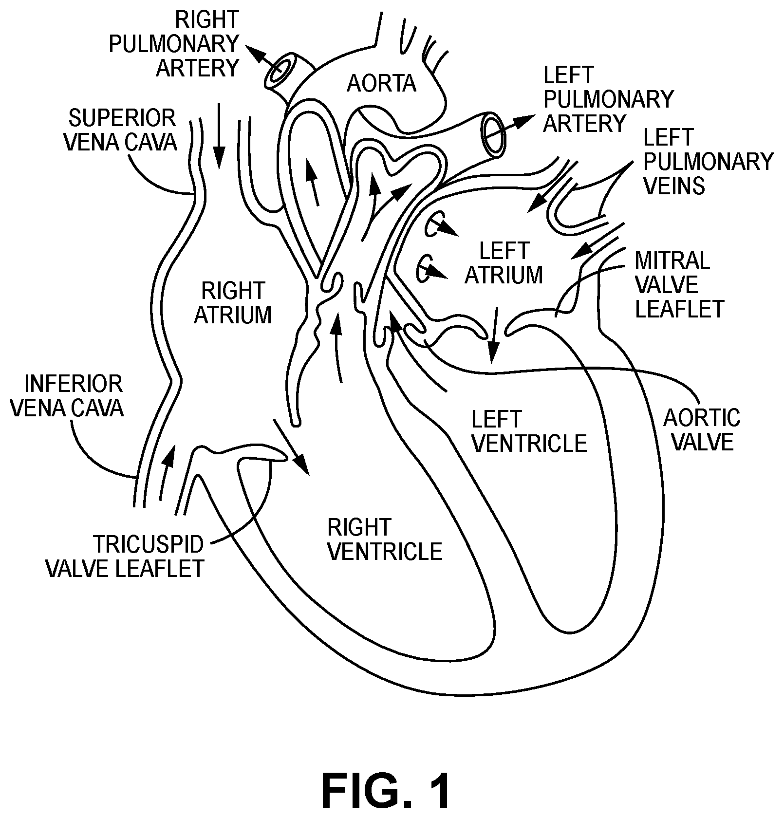
[0006] The human heart comprises four chambers and four heart valves that assist in the forward (antegrade) flow of blood through the heart. The chambers include the left atrium, left ventricle, right atrium and right ventricle. The four heart valves include the mitral valve, the tricuspid valve, the aortic valve and the pulmonary valve. See generally FIG. 1.
[0007] The mitral valve is located between the left atrium and left ventricle and helps control the flow of blood from the left atrium to the left ventricle by acting as a one-way valve to prevent backflow into the left atrium. Similarly, the tricuspid valve is located between the right atrium and the right ventricle, while the aortic valve and the pulmonary valve are semilunar valves located in arteries flowing blood away from the heart. The valves are all one-way valves, with leaflets that open to allow forward (antegrade) blood flow. The normally functioning valve leaflets close under the pressure exerted by reverse blood to prevent backflow (retrograde) of the blood into the chamber it just flowed out of. For example, the mitral valve when working properly provides a one-way valving between the left atrium and the left ventricle, opening to allow antegrade flow from the left atrium to the left ventricle and closing to prevent retrograde flow from the left ventricle into the left atrium. This retrograde flow, when present, is known as mitral regurgitation or mitral valve regurgitation.
[0008] Native heart valves may be, or become, dysfunctional for a variety of reasons and/or conditions including but not limited to disease, trauma, congenital malformations, and aging. These types of conditions may cause the valve structure to fail to close properly resulting in regurgitant retrograde flow of blood from the left ventricle to the left atrium in the case of a mitral valve failure.
[0009] Mitral valve regurgitation is a specific problem resulting from a dysfunctional mitral valve that allows at least some retrograde blood flow back into the left atrium from the right atrium. In some cases, the dysfunction results from mitral valve leaflet(s) that prolapse up into the left atrial chamber, i.e., above the upper surface of the annulus instead of connecting or coapting to block retrograde flow. This backflow of blood places a burden on the left ventricle with a volume load that may lead to a series of left ventricular compensatory adaptations and adjustments, including remodeling of the ventricular chamber size and shape, that vary considerably during the prolonged clinical course of mitral regurgitation.
[0010] Regurgitation can be a problem with native heart valves generally, including tricuspid, aortic and pulmonary valves as well as mitral valves.
[0011] Native heart valves generally, e.g., mitral valves, therefore, may require functional repair and/or assistance, including a partial or complete replacement. Such intervention may take several forms including open heart surgery and open heart implantation of a replacement heart valve. See e.g., U.S. Pat. No. 4,106,129 (Carpentier), for a procedure that is highly invasive, fraught with patient risks, and requiring not only an extended hospitalization but also a highly painful recovery period.
[0012] Less invasive methods and devices for replacing a dysfunctional heart valve are also known and involve percutaneous access and catheter-facilitated delivery of the replacement valve. Most of these solutions involve a replacement heart valve attached to a structural support such as a stent, commonly known in the art, or other form of wire network designed to expand upon release from a delivery catheter. See, e.g., U.S. Pat. No. 3,657,744 (Ersek); U.S. Pat. No. 5,411,552 (Andersen). The self-expansion variants of the supporting stent assist in positioning the valve, and holding the expanded device in position, within the subject heart chamber or vessel. This self-expanded form also presents problems when, as is often the case, the device is not properly positioned in the first positioning attempt and, therefore, must be recaptured and positionally adjusted. This recapturing process in the case of a fully, or even partially, expanded device requires re-collapsing the device to a point that allows the operator to retract the collapsed device back into a delivery sheath or catheter, adjust the inbound position for the device and then re-expand to the proper position by redeploying the positionally-adjusted device distally out of the delivery sheath or catheter. Collapsing the already expanded device is difficult because the expanded stent or wire network is generally designed to achieve the expanded state which also resists contractive or collapsing forces.
[0013] Besides the open heart surgical approach discussed above, gaining access to the valve of interest is achieved percutaneously via one of at least the following known access routes: transapical; transfemoral; transatrial; and trans septal delivery techniques.
[0014] Generally, the art is focused on systems and methods that, using one of the above-described known access routes, allow a partial delivery of the collapsed valve device, wherein one end of the device is released from a delivery sheath or catheter and expanded for an initial positioning followed by full release and expansion when proper positioning is achieved. See, e.g., U.S. Pat. No. 8,852,271 (Murray, III); U.S. Pat. No. 8,747,459 (Nguyen); U.S. Pat. No. 8,814,931 (Wang); U.S. Pat. No. 9,402,720 (Richter); U.S. Pat. No. 8,986,372 (Murray, III); and U.S. Pat. No. 9,277,991 (Salahieh); and U.S. Pat. Pub. Nos. 2015/0272731 (Racchini); and 2016/0235531 (Ciobanu).
[0015] In addition, known "replacement" prosthetic heart valves are intended for full replacement of the native heart valve. Therefore, these replacement heart valves physically engage tissue within the annular throat, i.e., below the annular plane and upper annular surface, and/or valve leaflets, thereby eliminating all remaining functionality of the native valve and making the patient completely reliant on the replacement valve. Generally speaking, it is a preferred solution that maintains and/or retains the native function of a heart valve, thus supplementation of the valve is preferred rather than full replacement. Obviously, there will be cases when native valve has either lost virtually complete functionality before the interventional implantation procedure, or the native valve continues to lose functionality after the implantation procedure. The preferred solution is delivery and implantation of a valve device that will function both as an adjunctive and/or supplementary functional valve as well as be fully capable of replacing the native function of a valve that has lost, or will lose, most or all of its functionality. However, the inventive solutions described infra will apply generally to all types and forms of heart valve devices, unless otherwise specified. The present disclosure also applies, as the skilled artisan will recognize, to stents generally.
[0016] Further, known solutions for, e.g., the mitral valve replacement systems, devices and methods require 2-chamber solutions, i.e., there is involvement and engagement of the implanted replacement valve device in the left atrium and the left ventricle. Generally, these solutions include a radially expanding stent in the left atrium, with anchoring or tethering (disposed downward through the native annulus or annular throat) connected from the stent device down through the annular throat, with the sub-annular surface within the left ventricle, the left ventricular chordae tendineae and even into the left ventricle wall surface(s). See, e.g., the MitraClip.RTM. marketed by the Abbott Group and currently the only US approved repair device. With the MitraClip.RTM. a catheter containing the MitraClip.RTM. is inserted into the femoral vein. The device enters the heart through the inferior vena cava to the right atrium and delivered trans-septally. The MitraClip.RTM. passes through the annulus into the left ventricle and sits below the leaflets, clipping the leaflets to decrease regurgitation.
[0017] Such 2-chamber and native annulus solutions are unnecessary bulky and therefore more difficult to deliver and to position/recapture/reposition from a strictly structural perspective. Further, the 2-chamber solutions present difficulties in terms of making the ventricular anchoring and/or tethering connections required to hold position. Moreover, these solutions interfere with the native valve functionality as described above because the device portions that are disposed within the left ventricle must be routed through the native annulus and/or annular throat and native mitral valve, thereby disrupting any remaining coaptation capability of the native leaflets. In addition, the 2-chamber solutions generally require an invasive anchoring of some of the native tissue, resulting in unnecessary trauma and potential complication.
[0018] It will be further recognized that the 2-chamber mitral valve solutions require sub-annular and/or ventricular engagement with anchors, tethers and the like precisely because the atrial portion of the device fails to adequately anchor itself to the atrial chamber and/or upper portion of the annulus. Again, some of the embodiments, or portions thereof, described herein are readily applicable to single or 2-chamber solutions, unless otherwise indicated.
[0019] Finally, known prosthetic cardiac valves consist of two or three leaflets that are arranged to act as a one-way valve, permitting fluid flow therethrough in the antegrade direction while preventing retrograde flow. The native mitral valve is located retrosternally at the fourth costal cartilage, consisting of an anterior and posterior leaflet, chordae tendinae, papillary muscles, ventricular wall and annulus connected to the atria. Each native leaflet is supported by chordae tendinae that are attached to papillary muscles which become taut with each ventricular contraction preserving valvular competence. Both the anterior and posterior leaflets of the native valve are attached via primary, secondary and tertiary chordae to both the antero-lateral and posterio-medial papillary muscles. A disruption in either papillary muscle in the setting of myocardial injury, can result in dysfunction of either the anterior or posterior leaflet of the mitral valve. Other mechanisms may result in failure of one, or both of the native mitral leaflets. In the case of a single mitral valve leaflet failure, the regurgitation may take the form of a non-central, eccentric jet of blood back into the left atrium. Other leaflet failures may comprise a more centralized regurgitation jet. Known prosthetic valve replacements generally comprise leaflets which are arranged to mimic the native valve structure, which may over time become susceptible to similar regurgitation outcomes.
[0020] The applications for collapsible and expandable stents are not limited to prosthetic heart valve implants. Vascular stents are commonly used and are generally collapsible to facilitate delivery through the lumen of a delivery catheter to the working site where the stent is translated out of the lumen of the catheter and it is expanded, either by a self-expanding means or through an expanding mechanism such as, inter alia, an expandable balloon.
[0021] As discussed above, known delivery methods and devices comprise expandable prosthetic valve stents and vascular stents that are collapsed during delivery via a delivery catheter. The problems with such collapsing and expanding structures include placing strain on the regions of the structure, e.g., stent, that must bend to accommodate the collapsing and expanding states. Further, the collapsed geometry in known devices may not be controlled or predictable, adding to the strain on the collapsing and expanding structure elements. Thus, the structures and methods for achieving the collapsed state within the delivery catheter or sheath lumen must allow predictable and repeatable collapsing to maintain and retain the integrity of the collapsing structure. Moreover, the stent, e.g., prosthetic heart valve or vascular stent, may comprise biological and/or biologically compatible material that cannot be allowed to become dry. Therefore, retaining a fluid reservoir within which the subject stent may reside is critical.
[0022] Various embodiments of the present invention address these, inter alia, issues.
BRIEF SUMMARY OF THE INVENTION
[0023] A device and method for predictably and controlling the collapsing of a collapsible and expandable stent for subsequent translation through a delivery sheath lumen to an anatomical target such as a heart valve or intravascular location for expansion and implantation. The loading device defines in inner lumen comprising a successively decreasing, from the proximal to the distal direction, inner diameter to a region of constant inner diameter wherein the stent is in a collapsed configuration. The device and method may provide for an at least partially collapsed configuration of the stent that may be further collapsed as a part of the implantation procedure and may comprise a stent that is pre-loaded for future use.
BRIEF DESCRIPTION OF THE SEVERAL VIEWS OF THE DRAWINGS
[0024] FIG. 1 illustrates certain features of the heart in cross-section.
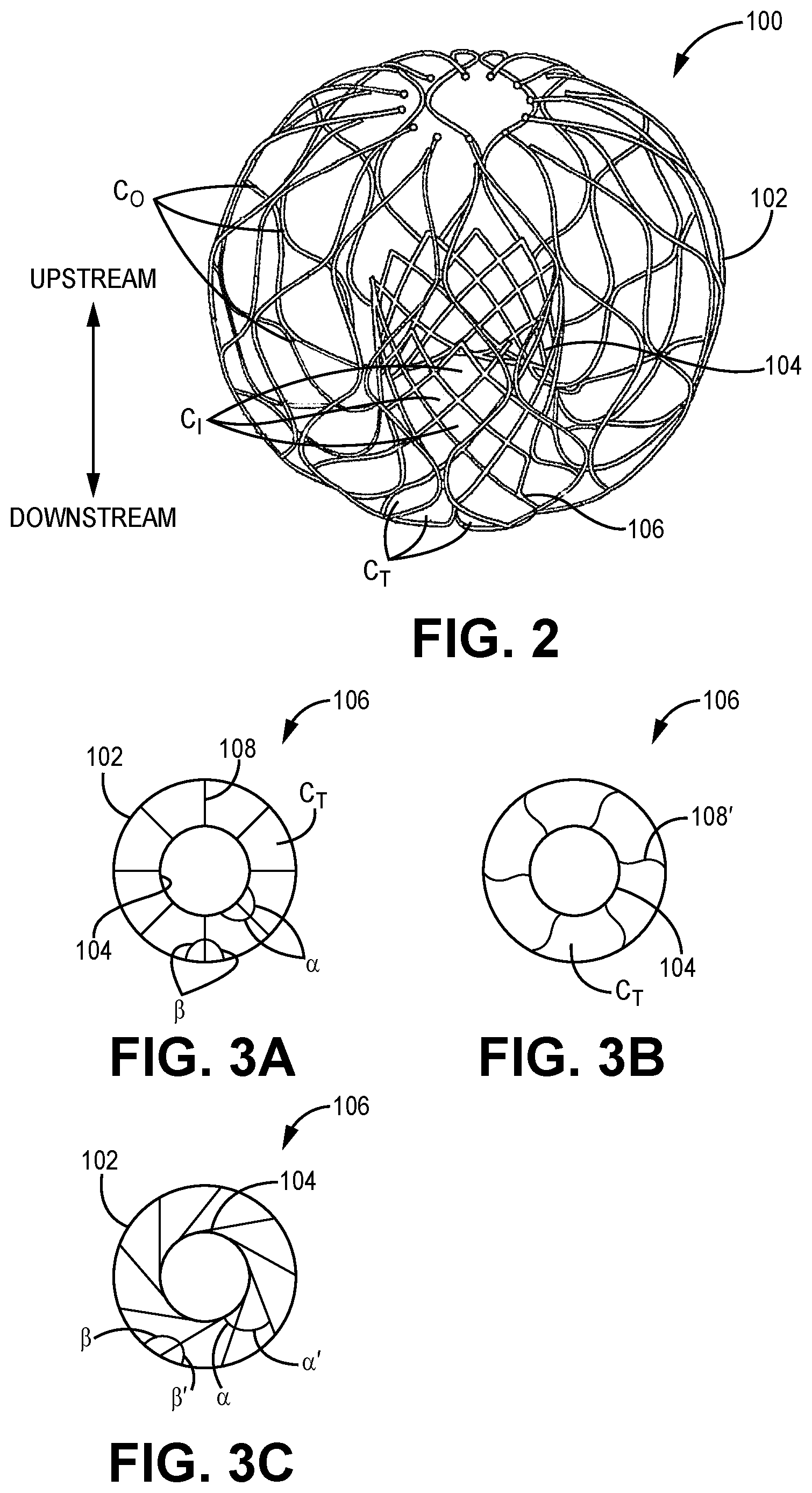
[0025] FIG. 2 illustrates a perspective view of an exemplary stent.
[0026] FIG. 3A illustrates a bottom view of one embodiment of a transition section of the exemplary stent of FIG. 2.
[0027] FIG. 3B illustrates a bottom view of one embodiment of a transition section of the exemplary stent of FIG. 2.
[0028] FIG. 3C illustrates a bottom view of one embodiment of a transition section of the exemplary stent of FIG. 2.
[0029] FIG. 4A illustrates a bottom view of one embodiment of a collapsed transition section of the exemplary stent of FIG. 2.
[0030] FIG. 4B illustrates a bottom view of one embodiment of a collapsed transition section of the exemplary stent of FIG. 2.
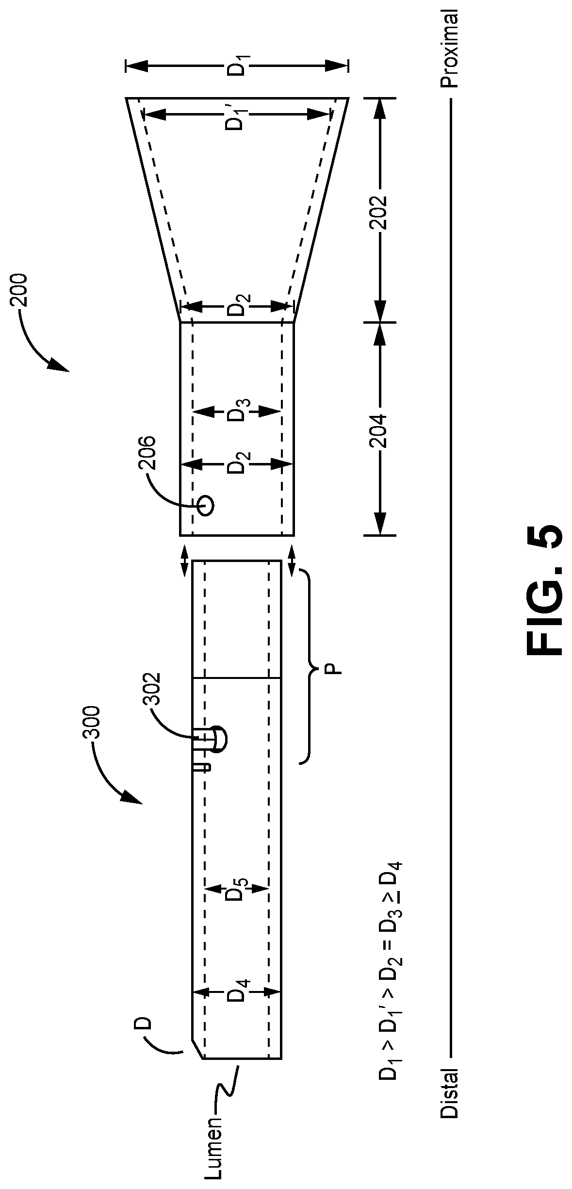
[0031] FIG. 5 illustrates a side broken away view of one embodiment of the present invention.
[0032] FIG. 6 illustrates a perspective view of one embodiment of the present invention.
DETAILED DESCRIPTION OF THE INVENTION
[0033] Generally, various embodiments of the present invention are directed to devices and methods for achieving a predictable collapsed configuration or state for a collapsible and expandable support structure or stent as well as providing a mechanism for ensuring moisture retention within biological materials that may be attached or otherwise integrated with the collapsible and expandable support structure during the collapsing step.
[0034] The support structure or stent has multiple functions to aid with the treatment of cardiac valve regurgitation (mitral or tricuspid). These functions include its function as a scaffold for the functioning 4C valve, apposition to the atrial anatomy, optimized radial force for compliance with atrial distension, ability to load and deploy from a minimally invasive delivery system, and geometry to support with mitigating against paravalvular leak (PVL). The design features of the stent are adapted to meet one or more of the functions identified above. Specific design features and attributes for exemplary stents are discussed in detail below to assist in understanding of the utility of the funneling loading device and related methods. As discussed above, the invention is not limited to prosthetic heart valves comprising stent support structures, but may also be applied to collapsible and expandable stents such as commonly used for intravascular procedures.
[0035] Certain exemplary embodiment stent design concepts are intended to support minimally invasive procedures for the treatment of valvular regurgitation--mitral, tricuspid and/or otherwise. The stents may be self-expandable (e.g. nitinol or similar materials) or balloon expandable (e.g. cobalt chromium or similar materials). The stents are typically made of cells that may be open celled diamond like structures or continuous structures that have a working cell element. The stents may also be constructed using tubing, wires, braids or similar structures. Specific design features that aid with the functioning of the stent are described in detail below.
[0036] Stent "Iris" Transition Cells
[0037] With reference now to FIGS. 2-3B, one embodiment of the stent 100 of the present invention comprises an outer section 102--that may generally be circular though need not be a perfectly round circular structure when fully and/or partially expanded--and an inner valve support section 104--which may be cylindrical but need not be a constant diameter cylinder and is adapted to support and retain prosthetic valve leaflets (not shown in FIG. 2) within the inner valve support section 104, most preferably at a point that located above the native annulus, e.g., the mitral valve annulus, though other attachment points for the prosthetic leaflets are within the scope of the present invention. Further, as discussed above, the stent 100 may be configured to supplement and/or replace the function of the tricuspid valve. A preferred construction comprises the prosthetic leaflets disposed above the native leaflets, wherein the prosthetic leaflets are attached and spaced sufficiently away from (above) the native leaflets so as to not physically interfere or interact with the native leaflets. However, certain embodiments contemplate some interaction with the native leaflets.
[0038] Individual cells C.sub.O forming the outer section 102 of stent 100 are visible in FIG. 2 as open cell regions defined by the material used to form the expandable stent 100.
[0039] Individual cells C.sub.I forming the inner valve support section 104 are also illustrated as open cells regions formed within an inner region R defined by outer section 102, wherein the inner valve support section extends radially upward into the inner region R. As shown, individual cells C.sub.I are of a different size, and may comprise a different shape, than that of individual cells C.sub.O.
[0040] The region of stent 100 that facilitates the radially inward transition of the stent 100 from the outer section 102 to the inner section 104 of the stent 100 is the transition cell region 106. Transition cell region 106 may comprise cells C.sub.T that may comprise a different size and/or shape that either the outer section cells C.sub.O and/or the inner section cells C.sub.I. The outer and/or inner regions 102, 104, and/or transition cell region 106 of the stent 100 may be constructed from one continuous structure or may combine two or more structures to achieve intended design goals. Transition cell region 106 comprises generally a radially upward turn to allow the inner valve support section 104 to reside within the inner region 102 as shown in FIG. 2. In some embodiments, the lower portion of inner valve support section 104, that is the portion of the inner valve support section 104 that is in connection with the cells C.sub.T of transition cell region 106 may also comprise a curving shape to facilitate and/or complete the radially upward turn into the inner region 102.
[0041] The geometry and/or shape of the transition cells C.sub.T may be substantially straight segments when expanded as in FIG. 3A below or may, as shown in FIG. 3B, incorporate an offset or a twist in the stent cell pattern when expanded to allow for a controlled compression of the stent. Exemplary cross-sectional geometry of the transition cell region 106 viewed from the bottom of stent 100 is represented schematically in FIGS. 3A and 3B.
[0042] This transition cell region 106 of the stent 100 may be a strut, completed cell section or a partial cell section. The transition cell region 106 may have any number of struts (minimum of 3) or cell sections as generally required to meet design needs. Transition cells C.sub.T or struts may be evenly spaced and formed by substantially straight and equally spaced apart struts 108 as shown in FIG. 3A, that extend away from the inner valve support section 104 with equal angles .alpha. on both sides of the strut 108 and equal angles .beta. on both sides of strut 108 with respect to its intersection or integration with outer support section 102.
[0043] In a preferred embodiment, the struts 108 of transition section 106 may be straight as in FIG. 3A, but with non-equal angles relative to the inner valve support section 104 and outer support section 102 as shown in FIG. 3C. There, the straight struts 108 are slanted so that a smaller angle .alpha. and a larger angle .alpha.' are provided relative to the inner valve support section 104. Similarly, a smaller angle .beta.' and a larger angle .beta. are provided relative to the outer support section 102. This allows a compressed nesting of the slanted struts 108 of transition section 106.
[0044] In another preferred embodiment, the transition cell region 106 may comprise transition cell struts 108' that comprise transition cells CT that are formed by struts 108' having an offset, i.e., not straight, are twisted and/or curvilinear. The degree of offset and/or twist and/or curvature of the struts 108', and therefore the size and/or shape of the resultant expanded cells CT may be varied dependent on the number of cells/struts in the transition cell region 106, packing density when the stent is collapsed, and stress/strain distribution limitations of the transition cell region 106.
[0045] The structure of FIGS. 3B and 3C are preferred over the straight transition cell region 106 structure of FIG. 3A for several reasons. FIG. 4A shows a transition cell region 106 in a collapsed form using the substantially straight struts 108 of FIG. 3A and with, undesirable, gaps G between selected struts 108. Though this resultant gapping collapsed transitional cell region 106 is workable, it is not optimal.
[0046] Thus, the transition section 106 of FIG. 4B, using e.g., the offset and/or twisted and/or curved plurality of struts 108' of FIG. 3B or the slanted straight struts 108 of FIG. 3C, allows for a controlled and predictable collapsed form of the stent, without gapping between the struts 108'. This, in turn, minimizes the amount of stress/strain concentration at the lower region of the stent 100 during collapsing as is required for delivery of the expandable stent 100 to the heart region of interest. Additionally, the collapse of the cells is also symmetrical and uniform, which could aid with mitigating against damage to the valve tissue or fabric when it is attached to the stent cells. Reduction in overall stress/strain of the transition strut section may benefit the durability of the stent and the valve tissue.
[0047] A feature of certain embodiments of the transition cell region 106 as shown in FIGS. 3B and 3C and 4B, i.e., with offset, twisted and/or curved struts 108' or slanted straight struts 108, is that, as best shown in FIG. 3B, the struts 108' each comprise the same offset, twist and/or curvature. This, in turn, enables a close nesting of adjacent struts 108' as the stent 100 is collapsed down for delivery and subsequent expansion. Thus, as the stent is collapsed for loading into a delivery system, the transition section design allows for a controlled compression of the stent, and reduces the stress concentration on the stent cells. of the transition strut section may benefit the durability of the stent and the valve tissue.
[0048] As the skilled artisan will now recognize from the above, the geometry of the exemplary stent's struts enables a transition from expanded to collapsed. The stent that may be collapsed using the following inventive embodiments is certainly not restricted to the exemplary cases described above. Any stent requiring collapsing from an expanded configuration to achieve a configuration that fits within the lumen of a delivery sheath may be collapsed with the present inventions.
[0049] Thus, FIG. 5 illustrates an exemplary loading device 200 that may initiate the transition of the exemplary stent from expanded to collapsed, wherein the collapsed state or configuration is prepared and sufficient for translation into and along the delivery catheter or sheath to the targeted anatomical location.
[0050] FIG. 5 therefore illustrates a loading funnel 200 on the proximal side of the image with a sheath 300, which may comprise modifications to known delivery catheters as described herein. The loading funnel 200 and sheath 300 are illustrated as two separate elements that may be removably connected using known techniques. However, as the skilled artisan will recognize, the loading funnel 200 and sheath 300 may be preassembled and/or manufactured as an integrated unit in certain embodiments. The loading funnel 200 comprises a proximal decreasing diameter (from proximal to distal) section 202, illustrated as conical but in other embodiments may comprise a curvilinear and or concave profile. In each case, the dimensional requirement is that the inner diameter D1' of the proximal decreasing diameter section 202 comprises a lumen comprising a smoothly decreasing inner diameter moving from the proximal inner diameter D1' to the distal inner diameter D2. Thus, proximal decreasing diameter section 202 comprises a maximum inner diameter (shown as D1') at its proximal end and a minimum inner diameter at its distal end (shown as D2). And, as shown, proximal outer diameter D1 of proximal section 202 is greater than proximal inner diameter D1'.
[0051] The decreasing diameter proximal section 202 of loading funnel 200 transitions distally into a constant diameter section 204, comprising an inner diameter D3 that is substantially the same as the smallest inner diameter D2 of the decreasing diameter proximal section 202 at its distal end, the transition therebetween preferably smooth to facilitate stressless translation of the collapsing exemplary stent therealong.
[0052] Transitional sheath 300 comprises a proximal end portion P and a distal D end, an outer diameter D4 and defining a lumen comprising inner diameter D5, wherein both D4 and D5 are substantially constant. The lumen for each of devices 200 and 300 is shown in dashed lines in FIG. 5.
[0053] Outer diameter D4 of sheath 300 may be the same as, or smaller than, the inner diameter D3 of the constant diameter section 204 of loading funnel 200. Thus, as shown, the proximal end portion P of sheath 300 is adapted or configured to fit within at least a distal portion of the lumen of the constant diameter section 204 of the loading funnel 200 to create a lumen that is fluidly communicating from the proximal end of the loading sheath 200 to the distal end D of the sheath 300. Generally, and without limitation, the various relevant diameter relationships are as follows, using the nomenclature provided above and in FIG. 5:
D1>D1'>D2=D3.gtoreq.D4
[0054] Sheath 300 may be removably connected with the constant diameter section 204 in a variety of ways, including but certainly not limited to: a frictional fit and/or the illustrated detent male member 206 disposed on constant diameter section 204 of loading funnel 200 until engaged, and pushed radially outwardly, by the proximal end portion P of sheath 300. Ultimately, when the male member 206 aligns with the slot or aperture 302, male member 206 may, as the skilled artisan will recognize, drop or snap within the receiving aperture 302 and/or slot as illustratively defined in the outer wall of constant diameter section 204 of sheath 300. In some cases, the slot 302 may allow relative rotation of the sheath 300 and loading funnel 200 within the slot 302, thus enabling relative rotation within the limits of the length of the slot 302 between the loading funnel 200 and the transitional sheath 300. As the skilled artisan will recognize, the above male member/slot or aperture arrangement may be effectively reversed: wherein the male member 206 may be disposed on the sheath 300 and the slot or aperture may be disposed on the constant diameter section 204 of loading funnel 200. Other possible connection alternatives, within limitation, between loading funnel 200 and sheath 300 may comprise a threaded connection; and a frictional fit. Still more alternatively, the components 200, 300 may be provided as a single unit, wherein the inner diameter of the single unit distal of the decreasing diameter section is constant. What is required in all cases is that the loading funnel 200 and sheath 300 are functionally connected to provide the dimensional features described above.
[0055] In some embodiments, the proximal end portion P of sheath 300 when engaged within constant diameter section 204 of loading funnel may extends proximally to the distal end of loading funnel 202, effectively sliding through the entire length of the lumen of constant diameter section 204. In other embodiments, proximal end portion P engages only a portion of the length of the lumen of constant diameter section 204.
[0056] The collapsing of an exemplary collapsible stent from an expanded configuration may be achieved by translating the expanded stent distally into the lumen of loading funnel 200 progressively along and through the decreasing diameter section 202, where the walls of loading funnel's lumen exert constant and equal pressure on the stent, causing a progressive, predictable and relatively stress-free collapsing and distal translation into the sheath 300 comprising lumen of inner diameter D5. At this stage, the exemplary stent is collapsed and ready for translation distally to the anatomical target. Release of the exemplary stent from the distal end of sheath 300 allows the stent, if self-expanding, to expand to its working expanded configuration. In other cases the stent may require additional assistance to expand, e.g., through push/pull wires and/or expanding balloons as is known in the art.
[0057] FIG. 6 provides an alternative, clamshell type construction for the transitional sheath 300', wherein the transitional sheath 300' is formed from a planar sheet 304 that may have a precurved shape as illustrated. The loading funnel 200 is as described above in connection with FIG. 5.
[0058] As the planar sheet 304 is reduced in diameter to slidingly fit within the constant diameter section 204 of the loading funnel 200, and form sheath 300', the male member 206 described above located on loading funnel 200, may align with and fit within an aperture or slot 302' of transitional sheath 300' to provide a removable locking fit between transitional sheath 300' and loading funnel 200 as described above. As noted above in the embodiment of FIG. 5, male member 206 and aperture or slot 302' may reverse positions in the embodiment of FIG. 6. In the case of a 302', the loading funnel 200 may rotate relative to the sheath 300', as the male member 206 rotates within the slot 302'. In certain cases, the clamshell type sheath 300' of FIG. 6 may not reach complete closure along its length when reduced in diameter to fit within the constant diameter section 204 of transition sheath 300', thus leaving a longitudinal slot along the transitional sheath 300'. The male member 206 of constant diameter section 204 may be guided along this longitudinal slot to the radial slot 302' shown in FIG. 6, where it may be rotated to removably lock the two elements together, or the male member 206 and slot 302' may be reversed in position as described above.
[0059] The structure of the loading device now explained, the skilled artisan will recognize the utility in effecting transition of a stent from an expanded size to a predetermined collapsed size with a predetermined diameter. Thus, the exemplary stent shown above may be slowly translated along the decreasing diameter section. As the stent is advanced, the inner walls of the decreasing diameter section 202 of loading funnel 200 exert a force that is circumferentially equal around the stent, thus enabling the stent to collapse along the points of least resistance and least stress. As discussed above, the circular and/or spiral struts will enable a predetermined, predictable and repeatable collapsing motion, leading to a predetermined, predictable and repeatable collapsed shape. When the stent has been collapsed within the constant diameter section 204 of loading funnel 200 and/or the constant diameter inner lumen of sheath 300, 300', the collapsed stent may be translated therealong to the anatomical location of interest. When the collapsed stent is released from the distal end of the inner lumen of 300, 300', it will be allowed to biasingly expand, effectively reversing the collapsing motion to reach an expanded state or configuration.
[0060] In some cases, as discussed, sheath 300, 300' may comprise a transitional sheath that provides a transition to connect with a delivery sheath or catheter comprising the same or similar inner diameter. In other cases, sheath 300, 300' may form the delivery sheath or catheter.
[0061] The loading device discussed above, e.g., loading funnel 200 and transitional sheath 300, 300', further enables a stent to be pre-loaded for use. Thus, a stent may be collapsed and loaded into the loading funnel 202 lumen, together with fluid to keep the biological and/or biologically compatible material(s) properly wetted in preparation for translation, delivery and implant.
[0062] In some embodiments, the distal end of the constant diameter section 204 (or distal end of sheath 300, 300') may be capped or plugged to hold fluid in the lumen of decreasing diameter section 202 and/or constant diameter section 204 (and/or lumen of sheath 300, 300') and in other embodiments a cap may be placed over the proximal end of decreasing diameter section 202 to further aid in holding fluid therein. This arrangement may provide a longer storage mechanism for collapsed, or partially collapsed, stents comprising moisture-sensitive, biologic material.
[0063] Alternatively, the stent may be collapsed and translated into the lumen of sheath 300, 300' as described above, filled with fluid and capped or plugged at both ends to retain fluid to assist in protecting moisture-sensitive biological material associated with the stent.
[0064] Once loaded and fluid-immersed, the stent may be held for a period of time in the collapsed configuration and/or transported to the site of need.
[0065] The description of the invention and its applications as set forth herein is illustrative and is not intended to limit the scope of the invention. Features of various embodiments may be combined with other embodiments within the contemplation of this invention. Variations and modifications of the embodiments disclosed herein are possible, and practical alternatives to and equivalents of the various elements of the embodiments would be understood to those of ordinary skill in the art upon study of this patent document. These and other variations and modifications of the embodiments disclosed herein may be made without departing from the scope and spirit of the invention.
* * * * *
D00000
D00001
D00002
D00003
D00004
D00005
XML
uspto.report is an independent third-party trademark research tool that is not affiliated, endorsed, or sponsored by the United States Patent and Trademark Office (USPTO) or any other governmental organization. The information provided by uspto.report is based on publicly available data at the time of writing and is intended for informational purposes only.
While we strive to provide accurate and up-to-date information, we do not guarantee the accuracy, completeness, reliability, or suitability of the information displayed on this site. The use of this site is at your own risk. Any reliance you place on such information is therefore strictly at your own risk.
All official trademark data, including owner information, should be verified by visiting the official USPTO website at www.uspto.gov. This site is not intended to replace professional legal advice and should not be used as a substitute for consulting with a legal professional who is knowledgeable about trademark law.