Aneurysm Device And Delivery System
XU; Ruijiao ; et al.
U.S. patent application number 16/678478 was filed with the patent office on 2020-03-05 for aneurysm device and delivery system. This patent application is currently assigned to DePuy Synthes Products, Inc.. The applicant listed for this patent is DePuy Synthes Products, Inc.. Invention is credited to Lacey GOROCHOW, Ruijiao XU.
| Application Number | 20200069313 16/678478 |
| Document ID | / |
| Family ID | 69639269 |
| Filed Date | 2020-03-05 |


View All Diagrams
| United States Patent Application | 20200069313 |
| Kind Code | A1 |
| XU; Ruijiao ; et al. | March 5, 2020 |
ANEURYSM DEVICE AND DELIVERY SYSTEM
Abstract
The present disclosure relates to a braid for treating an aneurysm. The braid can include a proximal expandable portion for positioning inside the aneurysm and sealing across a neck of the aneurysm. The braid can also include a distal expandable portion distal of the proximal expandable portion, the distal expandable portion for filling the aneurysm.
| Inventors: | XU; Ruijiao; (Raynham, MA) ; GOROCHOW; Lacey; (Raynham, MA) | ||||||||||
| Applicant: |
|
||||||||||
|---|---|---|---|---|---|---|---|---|---|---|---|
| Assignee: | DePuy Synthes Products,
Inc. Raynham MA |
||||||||||
| Family ID: | 69639269 | ||||||||||
| Appl. No.: | 16/678478 | ||||||||||
| Filed: | November 8, 2019 |
Related U.S. Patent Documents
| Application Number | Filing Date | Patent Number | ||
|---|---|---|---|---|
| 15989725 | May 25, 2018 | |||
| 16678478 | ||||
| Current U.S. Class: | 1/1 |
| Current CPC Class: | A61B 17/12172 20130101; A61B 2017/12054 20130101; A61M 25/0021 20130101; A61M 2025/0042 20130101; A61M 25/0054 20130101; A61B 17/1214 20130101; A61B 17/12113 20130101 |
| International Class: | A61B 17/12 20060101 A61B017/12; A61M 25/00 20060101 A61M025/00 |
Claims
1. A braid for occluding an aneurysm, the braid comprising: a proximal expandable portion capable of moving from a collapsed state within a microcatheter to a deployed state within the aneurysm, wherein in the deployed state, the proximal expandable portion forms a proximal sack sealing about a neck of the aneurysm; a junction disposed at a distal end of the proximal expandable portion; and a distal expandable portion connected to the junction and distal of the proximal expandable portion, wherein the distal expandable portion is capable of moving from a collapsed state within the microcatheter to a deployed state whereby the distal expandable portion forms a distal sack at least partially filling the aneurysm; wherein the distal expandable portion is capable of applying an outward force on the proximal expandable portion to anchor it in the aneurysm.
2. The braid of claim 1, wherein once the proximal and distal expandable portions are in the deployed state, proximally translating the distal expandable portion causes the proximal expandable portion to move to an inverted configuration.
3. The braid of claim 1, wherein once the proximal and distal expandable portions are in the deployed state, proximally translating a distal sack of the distal expandable portion causes a proximal sack of the proximal expandable portion to invert into itself.
4. The braid of claim 3, wherein after being inverted into itself, the proximal expandable portion is movable between positions at or adjacent a neck of the aneurysm by proximally moving the braid before detaching from a delivery system at a detachment marker.
5. The braid of claim 3, wherein the proximal expandable portion forms a dual layer bowl when inverted into itself upon deployment.
6. The braid of claim 5, wherein the proximal expandable portion is made of a single heat shaped layer braid.
7. The braid of claim 5, wherein the dual layer is configured to increase metal coverage at or adjacent thereby promoting aneurysm embolization and flow diversion effect.
8. The braid of claim 1, wherein, during delivery, the proximal expandable portion contacts the distal expandable portion causing a resistive force facilitating inversion of the proximal expandable portion.
9. The braid of claim 1, further comprising: one or more coils connected to the distal expandable portion.
10. The braid of claim 9, wherein the one or more coils are positionable within the distal expandable portion in the deployed state.
11. The braid of claim 9, wherein the one or more coils are positionable at least partially out of the braid when delivered in the aneurysm.
12. The braid of claim 9, wherein a length of the one or more coils is adjustable.
13. The braid of claim 9, wherein during delivery, the one or more coils are delivered to the aneurysm first and then the distal expandable portion.
14. The braid of claim 1, wherein a porosity of the proximal expandable portion is less than a porosity of the distal expandable portion.
15. The braid of claim 1, wherein the distal expandable portion alone is capable of completely filling the aneurysm in the deployed state.
16. The braid of claim 1, wherein the junction is a radiopaque band visible under fluoroscopy.
17. The braid of claim 1, wherein the distal expandable portion is made of a single layer mesh with an open distal end.
18. The braid of claim 1, wherein the distal expandable portion is configured to be deployed first into the aneurysm to anchor against an aneurysm wall.
19. A system for treating an aneurysm, the system comprising: a microcatheter; a delivery tube translatably disposed in the microcatheter; and a braid detachably connected to the delivery tube and slideably disposed within the microcatheter in a collapsed state and distally translatable from within the microcatheter to a deployed state, the braid comprising: a proximal expandable portion capable of moving from the collapsed state within the microcatheter to the deployed state within the aneurysm, wherein in the deployed state, the proximal expandable portion forms a proximal sack sealing about a neck of the aneurysm; a junction disposed at a distal end of the proximal expandable portion; and a distal expandable portion connected to the junction and distal of the proximal expandable portion, wherein the distal expandable portion is capable of moving from a collapsed state within the microcatheter to a deployed state whereby the distal expandable portion forms a distal sack at least partially filling the aneurysm; wherein the braid expands to the deployed state as a distal end of the braid distally exits the microcatheter.
20. A method of delivering an occlusive device to an aneurysm, comprising: selectively positioning the braid in a vessel associated with the aneurysm, the braid comprising: the braid comprising a proximal expandable portion capable of moving from a collapsed state within the microcatheter to a deployed state within the aneurysm; a junction disposed at a distal end of the proximal expandable portion; and a distal expandable portion connected to the junction and distal of the proximal expandable portion, the distal expandable portion capable of moving from the collapsed state within the microcatheter to the deployed state at least partially filling the aneurysm; distally sliding the braid, by a delivery tube, from a microcatheter towards the aneurysm thereby at least partially filling the aneurysm by expanding the distal expandable portion inside the aneurysm to form a distal sack; anchoring the braid to the aneurysm by expanding the proximal expandable portion to form a proximal sack sealing about the neck of the aneurysm; and proximally translating the distal sack causing the proximal sack to invert into itself.
Description
CROSS-REFERENCE TO RELATED APPLICATIONS
[0001] The present application is a continuation-in-part of U.S. application Ser. No. 15/989,725 filed May 25, 2018, the contents of which are incorporated herein by reference in their entirety as if set forth verbatim.
FIELD
[0002] This disclosure relates to medical instruments, and more particularly, delivery systems for aneurysm therapy.
BACKGROUND
[0003] Aneurysms can be complicated and difficult to treat. For example, treatment access may be limited or unavailable when an aneurysm is located proximate critical tissues. Such factors are of particular concern with cranial aneurysms due to the brain tissue surrounding cranial vessels the corresponding limited treatment access.
[0004] Prior solutions have included endovascular treatment access whereby an internal volume of the aneurysm sac is removed or excluded from arterial blood pressure and flow. In this respect, because the interior walls of the aneurysm may continue being subjected to flow of blood and related pressure, aneurysm rupture remains possible.
[0005] Alternative to endovascular or other surgical approaches can include occlusive devices. Such devices have typically incorporated multiple embolic coils that are delivered to the vasculature using microcatheter delivery systems. For example, when treating cranial aneurysms, a delivery catheter with embolic coils is typically first inserted into non-cranial vasculature through a femoral artery in the hip or groin area. Thereafter, the catheter is guided to a location of interest within the cranium. The sac of the aneurysm can then be filled with the embolic material to create a thrombotic mass that protects the arterial walls from blood flow and related pressure. However, such occlusive devices do have certain shortcomings, including mass effect, which can cause compression on the brain and its nerves.
[0006] One particular type of occlusive approach endeavors to deliver and treat the entrance or "neck" of the aneurysm as opposed to the volume of the aneurysm by implanting a device in the parent vessel of the aneurysm. In such "neck" approaches, by minimizing blood flow across the neck, then a cessation of flow into the aneurysm may be achieved. In turn, a thrombotic mass may naturally form without having to deliver embolic materials into the aneurysm sac, as previously described. This approach is preferable to masses formed from embolic material since a natural mass can improve healing by reducing possible distention from arterial walls and permits reintegration into the original parent vessel shape along the neck plane of the aneurysm. It is understood that the neck plane is an imaginary surface where the inner most layer of the parent wall would be but for the aneurysm. However, neck-occlusive approaches, such as implanting a flow impeding device in the parent vessel, are not without drawbacks. Such an approach may impede blood flow into peripheral blood vessels while blocking the aneurysm neck in the parent vessel. Impeding flow to the peripheral blood vessel can unintentionally lead to severe damage if the openings of the vessels are blocked.
[0007] The solution of this disclosure resolves these and other issues of the art.
SUMMARY
[0008] In some embodiments, the present disclosure relates to a self-expanding braid for treating an aneurysm, the braid being configured to replace flow diverter(s), coil(s) and stenting without the need of dual antiplatelet therapy and treat aneurysms by filling the aneurysm sac and sealing the aneurysm neck.
[0009] In some embodiments, the braid can include a proximal expandable portion for positioning inside the aneurysm and sealing across a neck of the aneurysm. The braid can also include a distal expandable portion distal of the proximal expandable portion, the distal expandable portion fills the aneurysm and provides an outward force on the proximal portion for it to remain in place in the aneurysm.
[0010] In some embodiments, the braid can move from a collapsed state within a microcatheter to a deployed state distal of the microcatheter.
[0011] In some embodiments, in the deployed state, the proximal expandable portion forms an annular expanded segment for sealing about the neck of the aneurysm and the distal expandable portion forms a distal sack for filling the aneurysm. The annular expanded segment can be formed from a single continuous portion or multiple separate, discrete portions (e.g. a plurality of expanded portions that extend from a proximal end of the braid).
[0012] In some embodiments, a porosity of the proximal expandable portion can be less than a porosity of the distal expandable portion. The respective porosities are defined by dimensions of interstices, braid angle, braid wire thickness, heat treatment, and/or covering.
[0013] In some embodiments, the distal sack can be shaped to be spherical, saddled, ellipsoid shaped, or any other shape. The distal sack can also be a collapsible cage-like vaso-occlusive structure.
[0014] In some embodiments, the annular expanded segment can form, invert about, and surround a lower end of the distal sack. In some embodiments, the annular expanded segment overlays the distal sack (e.g., overlays external to the distal sack). Outer ends or portions of the distal sack can be oriented to press against the inner surface of the annular expanded segment. Outer ends or portions of the distal sack can be oriented to press against the proximal segment as the braid expands into the deployed state. A gap or a cavity can form between the annular expanded segment and the distal sack when the distal sack is pressed against the annular segment, including against the inner surface of the annular expanded segment. A gap or a cavity can also be formed between the annular expanded segment and the distal sack when the annular expanded segment is inverted about the distal sack
[0015] In some embodiments, the braid also includes a tapered segment disposed between the proximal and distal expandable portions. In this respect, the proximal expandable portion can include a porosity lower than a porosity of the tapered segment and/or the distal expandable portion. The proximal expandable portion can include an increased braid angle relative to a braid angle of the tapered segment and/or the distal expandable portion. The tapered segment can also include fewer wire segments than the proximal expandable portion and/or the distal expandable portion. In this respect, the proximal expandable portion, the distal expandable portion, and/or the tapered segment can have different braid properties.
[0016] In some embodiments, a buckle portion can be included in the braid that is defined between the tapered segment and the proximal expandable portion or the distal expandable portion.
[0017] In some embodiments, the braid has an open distal end and a proximal end of the braid is attached to a locking portion detachably connectable with a delivery tube.
[0018] In some embodiments, a system for treating an aneurysm is disclosed. The system includes a microcatheter, a delivery tube translatably disposed in the microcatheter, and a braid of this disclosure. The braid can be detachably connected to the delivery tube and slideably disposed within the microcatheter in a collapsed state and distally translatable from within the microcatheter to a deployed state. The braid can expand, including the distal and/or proximal expandable portions, to the deployed state as the distal end of the braid distally exits the microcatheter.
[0019] In some embodiments, the annular expanded segment overlays external to the distal sack as the braid distally translates from the microcatheter and the braid is pushed against the aneurysm wall.
[0020] In some embodiments, the system can include radiopaque entities such as platinum wires woven into the braid or drawn filled tube wires with platinum so that the device can be imaged under fluoroscopy. Including these entities will allow the end user to understand and visualize the location of the braid with respect to the aneurysm. An orientation and/or a position of the distal sack and/or the annular expanded segment can be adjustable by the braid being distally or proximally moved in the microcatheter.
[0021] In some embodiments, the system also includes a locking portion attached to a proximal end of the braid. In the collapsed state, the locking portion can be attached to a distal end of the delivery tube. In the deployed state, the locking portion can be detached from the delivery tube and the braid can be detached in the aneurysm.
[0022] In some embodiments, a method of delivering an occlusive device to an aneurysm, is also disclosed. The method can include attaching a proximal end of the braid to a distal end of a delivery tube; positioning a braid within a microcatheter; selectively positioning the braid with attached delivery tube in the vasculature (e.g. at the neck of the aneurysm); distally sliding the braid from a microcatheter, by the delivery tube, towards the aneurysm thereby expanding a distal expandable portion inside the aneurysm to form a distal sack and forming an annular expanded segment at a proximal end of the braid about the distal sack; releasing the braid, and withdrawing the delivery tube and the microcatheter from the aneurysm.
[0023] In some embodiments, filling the aneurysm by forming the distal sack.
[0024] In some embodiments, the selectively positioning of the braid comprises placing a distal end of the microcatheter at the neck of the aneurysm.
[0025] In some embodiments, the distal expandable portion is simultaneously expanding when the annular expanded segment is forming.
[0026] In some embodiments, the proximal segment expands after the distal segment is expanded.
[0027] In some embodiments, the method also includes attaching the locking portion at the proximal end of the braid and the distal end of the delivery tube; and releasing, by the locking portion, the delivery tube from the braid.
[0028] In some embodiments, the method also includes expanding the annular expanded segment so that the annular expanded segment overlays an outer surface of the distal sack.
[0029] In some embodiments, the method also includes pressing one or more outer ends of the distal sack against the annular expanded segment (e.g., the inner surface of the annular expanded segment) as the braid distally translates into the aneurysm.
[0030] In some embodiments, the method also includes forming a gap or a cavity between the annular expanded segment and the distal sack when the distal sack presses against the inner surface of the annular expanded segment.
[0031] In some embodiments, the method also includes forming a gap or a cavity between the annular expanded segment and the distal sack when the annular expanded segment inverts about the outer surface of the occlusive sack.
[0032] In some embodiments, the method also includes forming a tapered segment between the proximal and distal expandable portions. The method can also include making a porosity of the proximal expandable portion less than a porosity of the tapered segment and/or the distal expandable portion; positioning the proximal expandable portion adjacent or in communication with a neck of the aneurysm; and deflecting, diverting, and/or slowing a flow into the aneurysm. The method can also include making a flexibility of the proximal expandable portion less than a flexibility of the tapered segment and/or the distal expandable portion; positioning the proximal expandable portion adjacent or in communication with a neck of the aneurysm; and deflecting, diverting, and/or slowing a flow into the aneurysm. In some embodiments, the distal sack provides added flow diversion effect by providing another braid layer that blood has to flow through. The annular segment and proximal end of the distal sack may also provide an increased flow diversion effect as the blood has to flow through additional layers (e.g., three layers) of net like structures that comprise tiny pores.
[0033] In some embodiments, a method of using a braid for treating an aneurysm is disclosed. The method can include positioning the braid inside the aneurysm; distally moving the braid into the aneurysm; expanding a proximal expandable portion of the braid from a collapsed state to an expanded state thereby sealing a neck of the aneurysm; and expanding a distal expandable portion of the braid inside the aneurysm to form a distal sack thereby filling the aneurysm.
[0034] In some embodiments, the step of expanding the proximal expandable portion of the braid can include forming an annular expanded segment at a proximal end of the braid about the distal sack.
[0035] In some embodiments, the method can include overlaying the annular about an outer surface of the distal sack; and pressing outer ends of the distal sack against the inner surface of the annular segment as the braid expands into the deployed state to secure the device against the aneurysm wall.
[0036] In some embodiments, the method can include forming a gap or a cavity between the annular expanded segment and the distal sack when the distal sack presses against the annular segment.
[0037] In some embodiments, the method can include forming a tapered segment between the proximal and distal expandable portions. The method can also include making a porosity of the proximal expandable portion less than a porosity of the tapered segment and/or the distal expandable portion; and deflecting, diverting, and/or slowing a flow into the aneurysm. The method can also include making a flexibility of the proximal expandable portion less than a flexibility of the tapered segment and/or the distal expandable portion; and deflecting, diverting, and/or slowing a flow into the aneurysm.
[0038] In some embodiments, a braid is disclosed for occluding an aneurysm. The braid can include a proximal expandable portion capable of moving from a collapsed state within a microcatheter to a deployed state within the aneurysm, wherein in the deployed state, the proximal expandable portion forms a proximal sack sealing about a neck of the aneurysm. A junction can be disposed at a distal end of the proximal expandable portion. A distal expandable portion can be connected to the junction and distal of the proximal expandable portion, wherein the distal expandable portion is capable of moving from a collapsed state within the microcatheter to a deployed state whereby the distal expandable portion forms a distal sack at least partially filling the aneurysm. The distal expandable portion can be capable of applying an outward force on the proximal expandable portion to anchor it in the aneurysm.
[0039] In some embodiments, once the proximal and distal expandable portions are in the deployed state, proximally translating the distal expandable portion causes the proximal expandable portion to move to an inverted configuration.
[0040] In some embodiments, once the proximal and distal expandable portions are in the deployed state, proximally translating a distal sack of the distal expandable portion causes a proximal sack of the proximal expandable portion to invert into itself.
[0041] In some embodiments, after being inverted into itself, the proximal expandable portion is movable between positions at or adjacent a neck of the aneurysm by proximally moving the braid before detaching from a delivery system at a detachment marker.
[0042] In some embodiments, the proximal expandable portion forms a dual layer bowl when inverted into itself upon deployment.
[0043] In some embodiments, the proximal expandable portion is made of a single heat shaped layer braid.
[0044] In some embodiments, the dual layer is configured to increase metal coverage at or adjacent thereby promoting aneurysm embolization and flow diversion effect.
[0045] In some embodiments, during delivery, the proximal expandable portion contacts the distal expandable portion causing a resistive force facilitating inversion of the proximal expandable portion.
[0046] In some embodiments, one or more coils are connected to the distal expandable portion.
[0047] In some embodiments, the one or more coils are positionable within the distal expandable portion in the deployed state.
[0048] In some embodiments, the one or more coils are positionable at least partially out of the braid when delivered in the aneurysm.
[0049] In some embodiments, a length of the one or more coils is adjustable.
[0050] In some embodiments, during delivery, the one or more coils are delivered to the aneurysm first and then the distal expandable portion.
[0051] In some embodiments, a porosity of the proximal expandable portion is less than a porosity of the distal expandable portion.
[0052] In some embodiments, the distal expandable portion alone is capable of completely filling the aneurysm in the deployed state.
[0053] In some embodiments, the junction is a radiopaque band visible under fluoroscopy.
[0054] In some embodiments, the distal expandable portion is made of a single layer mesh with an open distal end.
[0055] In some embodiments, the distal expandable portion is made of a single layer mesh with an atraumatic distal end.
[0056] In some embodiments, the distal expandable portion is configured to be deployed first into the aneurysm to anchor against an aneurysm wall.
[0057] In some embodiments, the distal expandable portion and the proximal expandable portion are pressed together during heat set.
[0058] In some embodiments, a system is disclosed for treating an aneurysm. The system can include a microcatheter and a delivery tube translatably disposed in the microcatheter. A braid can be detachably connected to the delivery tube and slideably disposed within the microcatheter in a collapsed state and distally translatable from within the microcatheter to a deployed state. The braid can include a proximal expandable portion capable of moving from the collapsed state within the microcatheter to the deployed state within the aneurysm, wherein in the deployed state, the proximal expandable portion forms a proximal sack sealing about a neck of the aneurysm. A junction can be disposed in the braid at a distal end of the proximal expandable portion. A distal expandable portion of the braid can be connected to the junction and distal of the proximal expandable portion, wherein the distal expandable portion is capable of moving from a collapsed state within the microcatheter to a deployed state whereby the distal expandable portion forms a distal sack at least partially filling the aneurysm. The braid can expand to the deployed state as a distal end of the braid distally exits the microcatheter.
[0059] In some embodiments, a method of delivering an occlusive device to an aneurysm is disclosed, including selectively positioning a braid in a vessel associated with the aneurysm, the braid including a proximal expandable portion capable of moving from a collapsed state within the microcatheter to a deployed state within the aneurysm. A junction can be disposed at a distal end of the proximal expandable portion. A distal expandable portion can be connected to the junction and distal of the proximal expandable portion, the distal expandable portion capable of moving from the collapsed state within the microcatheter to the deployed state at least partially filling the aneurysm. The method can include distally sliding the braid, by a delivery tube, from a microcatheter towards the aneurysm thereby at least partially filling the aneurysm by expanding the distal expandable portion inside the aneurysm to form a distal sack; anchoring the braid to the aneurysm by expanding the proximal expandable portion to form a proximal sack sealing about the neck of the aneurysm; and proximally translating the distal sack causing the proximal sack to invert into itself.
[0060] In some embodiments, the method includes attaching a proximal end of a braid to a distal end of the delivery tube.
[0061] In some embodiments, the method includes releasing the braid.
[0062] In some embodiments, the method includes completely filling, by the distal sack, the aneurysm.
[0063] In some examples, the step of anchoring the distal expandable portion includes providing an outward force, by the distal sack, on the proximal expandable portion.
[0064] In some embodiments, the method includes attaching a locking portion to the delivery tube at the proximal end of the braid and the distal end of the delivery tube; and releasing, by the locking portion, the delivery tube from the braid.
[0065] In some embodiments, the step of inverting the proximal expandable portion causes the distal expandable portion to overlay an outer surface of the proximal expandable portion.
[0066] In some embodiments, the method includes further filling the aneurysm by extending one or more coils from the distal sack into the aneurysm.
[0067] In some embodiments, the method includes forming a dual layer bowl when the proximal sack is inverted into itself.
[0068] In some embodiments, the method includes contacting, by the proximal expandable portion during delivery, the distal expandable portion causing a resistive force that facilitates inversion of the proximal expandable portion.
[0069] In some embodiments, the method includes making a porosity of the proximal expandable portion less than a porosity of the distal expandable portion; positioning the proximal expandable portion adjacent or in communication with a neck of the aneurysm; and deflecting, diverting, or slowing a flow into the aneurysm.
[0070] In some embodiments, the method includes deploying the distal expandable portion into the aneurysm to anchor against an aneurysm wall before the proximal expandable portion.
[0071] In some embodiments, the method includes connecting one or more coils to the distal expandable portion.
[0072] In some embodiments, the method includes positioning one or more coils within the distal expandable portion in the deployed state.
[0073] In some embodiments, the method includes positioning one or more coils at least partially out of the braid when delivered in the aneurysm.
[0074] In some embodiments, the method includes adjusting a length of one or more coils of the braid.
[0075] In some embodiments, the method includes delivering one or more coils of the braid to the aneurysm first and then delivering the distal expandable portion.
[0076] Other aspects and features of the present disclosure will become apparent to those of ordinary skill in the art, upon reviewing the following detailed description in conjunction with the accompanying figures.
BRIEF DESCRIPTION OF THE DRAWINGS
[0077] Reference will now be made to the accompanying drawings, which are not necessarily drawn to scale.
[0078] FIG. 1 depicts an example occlusive device of this disclosure deployed into an aneurysm.
[0079] FIG. 2A is a schematic side view of an exemplary delivery system with an occlusive device collapsed within a microcatheter.
[0080] FIG. 2B is a schematic side view of an exemplary delivery system with an occlusive device deployed distal of a microcatheter.
[0081] FIG. 3 is an enlarged schematic side view of the braid of FIGS. 1-2 in an expanded state.
[0082] FIG. 4 is an enlarged schematic side view of another embodiment of a braid of this disclosure.
[0083] FIG. 5A is an enlarged schematic side view of the delivery system and braid of FIGS. 1-3 as the braid is being pushed into an example aneurysm.
[0084] FIG. 5B is an enlarged schematic side view of the delivery system and braid of FIGS. 1-3 as the braid is being pushed into an example aneurysm.
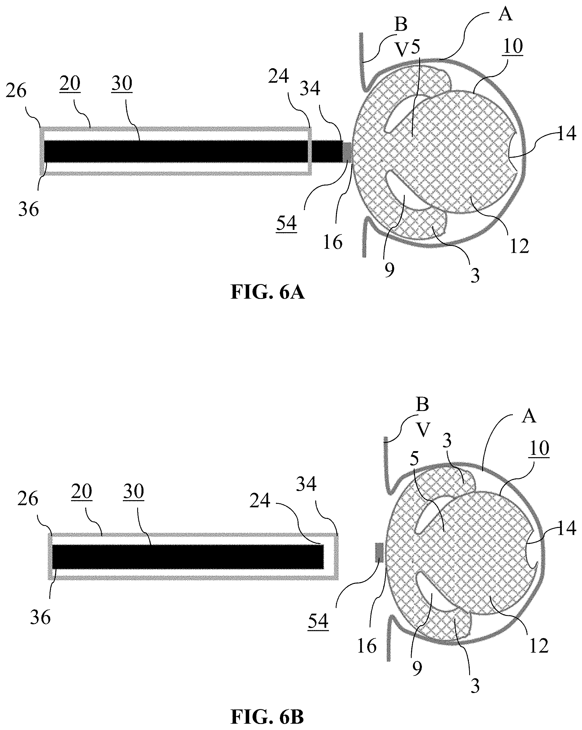
[0085] FIG. 6A is an enlarged schematic side view of the delivery system and braid of FIGS. 1-3 as the braid is being pushed into an example aneurysm.
[0086] FIG. 6B is an enlarged schematic side view of the delivery system and braid of FIGS. 1-3 as the braid is being pushed into an example aneurysm.
[0087] FIG. 7A is a perspective schematic view showing an exemplary delivery system for use with an example occlusive device.
[0088] FIG. 7B is a perspective schematic view of FIG. 7A but with partial cross-section of the delivery system and the occlusive device.
[0089] FIG. 8A is a perspective schematic view of FIGS. 7A-7B being deployed with partial cross-section of the delivery system and the occlusive device.
[0090] FIG. 8B is a perspective schematic view of FIGS. 7A-7B deployed with the exemplary delivery system detached from the occlusive device.
[0091] FIG. 9 is an enlarged schematic side view showing a distal segment single layer open configuration with an open distal end and proximal segment inverted.
[0092] FIG. 10A is an enlarged schematic side view showing a distal segment deployed first at the dome of an example aneurysm with a connection point.
[0093] FIG. 10B is an enlarged schematic side view showing the distal segment of FIG. 10A being pushed to cause inversion of the proximal segment.
[0094] FIG. 11A is an enlarged schematic side view showing the distal segment of FIGS. 10A-10B continuing to be pushed on the proximal segment.
[0095] FIG. 11B is an enlarged schematic side view showing the proximal segment of FIGS. 10A-11A being adjusted to locate at the aneurysm neck.
[0096] FIG. 12A shows an example braid configuration with a distal segment including a dual layer braid with coils contained within the braid.
[0097] FIG. 12B is an enlarged schematic side view showing the configuration of FIG. 12A after detachment in the aneurysm.
[0098] FIG. 13A shows an example braid configuration with a distal segment including a dual layer braid with coils contained at least partially outside of the braid.
[0099] FIG. 13B is an enlarged schematic side view showing the configuration of FIG. 13A after detachment in the aneurysm.
[0100] FIG. 14 is a flow diagram for a method of delivering an occlusive device.
[0101] FIG. 15 is a flow diagram for a method of delivering an occlusive device.
[0102] FIG. 16 is a flow diagram for a method of delivering an occlusive device.
DETAILED DESCRIPTION
[0103] Although example embodiments of the disclosed technology are explained in detail herein, it is to be understood that other embodiments are contemplated. Accordingly, it is not intended that the disclosed technology be limited in its scope to the details of construction and arrangement of components set forth in the following description or illustrated in the drawings. The disclosed technology is capable of other embodiments and of being practiced or carried out in various ways.
[0104] It must also be noted that, as used in the specification and the appended claims, the singular forms "a," "an" and "the" include plural referents unless the context clearly dictates otherwise. By "comprising" or "containing" or "including" it is meant that at least the named compound, element, particle, or method step is present in the composition or article or method, but does not exclude the presence of other compounds, materials, particles, method steps, even if the other such compounds, material, particles, method steps have the same function as what is named.
[0105] In describing example embodiments, terminology will be resorted to for the sake of clarity. It is intended that each term contemplates its broadest meaning as understood by those skilled in the art and includes all technical equivalents that operate in a similar manner to accomplish a similar purpose. It is also to be understood that the mention of one or more steps of a method does not preclude the presence of additional method steps or intervening method steps between those steps expressly identified. Steps of a method may be performed in a different order than those described herein without departing from the scope of the disclosed technology. Similarly, it is also to be understood that the mention of one or more components in a device or system does not preclude the presence of additional components or intervening components between those components expressly identified.
[0106] As discussed herein, vasculature can be that of any "subject" or "patient" including of any human or animal. It should be appreciated that an animal may be a variety of any applicable type, including, but not limited thereto, mammal, veterinarian animal, livestock animal or pet type animal, etc. As an example, the animal may be a laboratory animal specifically selected to have certain characteristics similar to a human (e.g., rat, dog, pig, monkey, or the like). It should be appreciated that the subject may be any applicable human patient, for example.
[0107] As discussed herein, "operator" may include a doctor, surgeon, or any other individual or delivery instrumentation associated with delivery of a braid body to the vasculature of a subject.
[0108] Relatedly, flow diverters that are deployed across the aneurysm neck can alter the flow of blood into the aneurysm. An example flow diverter can be a braided device with relatively low porosity. Over time, the aneurysms can heal by sealing the aneurysm neck with a high rate of success. However, flow diversion technology is not without limitations. Challenges include placement of the devices intra-vascularly due to vessel morphology, vessel tortuosity, or braid malapposition. In addition, patients receiving a flow diverter must be on anticoagulation medicine for an extended period to prevent vessel thrombosis. Intrasaccular devices also aim to cut circulation into the aneurysm while minimizing the amount of metal in the vessel and significantly cutting or eliminating the need for coagulation medication. These types of devices may also be easier to track and/or deploy at the lesion site.
[0109] It is understood that the herein disclosed solution can be configured to treat a relatively wide-neck bifurcation aneurysm, which are known to be difficult to treat because conventional treatment modalities are ineffective at producing complete occlusion. Treatment with coils and Y-stenting or bifurcation stents require the patient to be on dual antiplatelet therapy (DAPT). Treatment with a flow diverter alone can also block the other major artery and also require DAPT. Therefore, the solution of this disclosure resolves these and other needs in the art by providing a treatment option for wide-neck bifurcation aneurysms among others. Devices and systems disclosed herein addresses these and other drawbacks of previous approaches by using a single device to seal the aneurysm neck, in the aneurysm and not in the parent vessel. Turning to FIG. 1, an example braid 10 of this disclosure is shown deployed into an aneurysm A of blood vessel BV but not yet released from delivery system 40. The delivery system 40 can include a microcatheter 20 with a delivery tube 30 slideably disposed therein. Braid 10 can be moved by delivery tube 30 from a collapsed state within microcatheter 20 to a deployed state distal of the microcatheter 20 as in FIG. 1. A distal end 34 of delivery tube 30 may be attached to a proximal end 16 of braid 10 through a locking portion 54, as described more particularly below.
[0110] In FIG. 1, the microcatheter 20 has been delivered to the neck of aneurysm A and a distal sack formed by distal expandable portion 12 of braid 10 is shown filling aneurysm A. Portion 12 can be radially expanded form the distal sack in a predetermined shape and structure that outlines and supports the walls of the aneurysm A. For example, the distal sack of portion 12 can be shaped to be spherical, saddled, ellipsoid shaped, or any other shape. The distal sack of portion 12 can also be a collapsible cage-like vaso-occlusive structure. An annular expanded segment 3 is also shown formed by proximal expandable portion 13, portion 13 being proximal of portion 12. Segment 3 can be formed about the neck of aneurysm A. In some embodiments, segment 3 can be for positioning inside and sealing across the neck of the aneurysm A. Segment 3 can be formed from a single continuous portion (e.g. a single integrally formed mesh) or multiple separate, discrete portions (e.g. a plurality of discrete portions capable of expanding and extending from a proximal end 16 of the braid 10).
[0111] When moving to the deployed state, portion 13 can expand and form annular expanded segment 3 about and/or surrounding a lower proximal end of the distal sack of portion 12. For example, annular expanded segment 3 can form about and/or surround a tapered segment 5 that may be positioned between portions 12 and 13. Though only portions 12 and 13 are depicted interconnected with tapered segment 5, any number of additional expandable portions and/or segments could be included as needed or required. Braid 10 can be formed from multiple self-expanding multi-filament segments that can be formed from a mesh. Braid 10 can also include a buckle portion for facilitating expansion of portions 12 and/or 13 from collapsed to deployed states inside the aneurysm. One or more buckle portions can be positioned between portions 12 and 13, including on or about the tapered segment 5. Braid 10 can also have an open distal end 14 associated with segment 12 and a proximal end 16 associated with segment 13 intended to be positioned on or adjacent the neck of the aneurysm A. End 16 can also be attached to locking portion 54 that is configured for releasable attachment with distal end 34 of delivery tube 30.
[0112] The mesh of braid 10 can be defined by one or more mesh patterns, one or more discrete mesh portions, including portions 12 and 13 and/or tapered segment 5, and/or one or more mesh openings defined by braided filaments. For example, the mesh of braid 10 can include a porosity region associated with the distal sack of portion 12 and another porosity region associated with segment 3 of portion 13. In some embodiments, a porosity of portion 12 can be less than a porosity of portion 13. However, braid 10 is not so limited and other parts of braid 10 can have their porosities and other braid properties varied as needed or required. For example, portion 13 can include a porosity lower than a porosity of tapered segment 5. Similarly, porosity of portion 13 can be less than the porosity of portion 12 thereby providing more metal coverage at the neck of the aneurysm. The respective porosities of the various portions of braid 10 can be defined by varying dimensions of interstices, braid angle, braid wire thickness, heat treatment, mesh openings, covering, and/or the like. For example, the mesh of braid 10 shown in FIGS. 1 to 2B can include a different porosity region associated with each of segments 12, 13. In practice, the porosity of portion 12 can permit its outer distal sack to take on many shapes prior to, during, or after delivery to aneurysm. In some embodiments, portion 12 and 13 can have different visibility under fluoroscopy (e.g., portion 12 made of nitinol to retain its shape when deployed and portion 13 made of niti-platinum braid to provide visibility at the neck).
[0113] In some embodiments, segment 3 can overlay the distal sack of portion 12 in the deployed state. For example, segment 3 can overlay the outer surface of the distal sack of portion 12 as the braid 10 is distally translated by delivery tube 30 from microcatheter 20. Expansion of portions 12 and 13 can also occur as braid 10 is pushed against the aneurysm wall. Outer ends of distal sack of portion 12 can also be oriented to press against the annular expanded segment 3 as the braid 10 expands into the deployed state. Exemplary "pressing" is shown in the depicted orientation of FIG. 1 whereby a gap or a cavity 9 can form between segment 3 and the distal sack when segment 12 is pressed against the inner surface of the annular segment of portion 3. This gap or cavity 9 can serve as an "air cushion" so that as braid is distally pushed deeper into the aneurysm A, rupture is avoided since portions 12 and 13 have certain amount of give by being be pushed into the other and flexibly conform to the shape of aneurysm A.
[0114] The mesh of braid 10 can be comprised of a tube with proximal end 16 opened at opposite distal end 14. Proximal end 16 may also be closed and attached to locking portion 54. Braid 10 can be made of several materials such as deposited thin films or of one single material. The mesh of braid 10 can include multiple wires, for example from 4 to 96 wires. The number of wires can be a factor in controlling material properties of the braid 10, including the porosity, shape in the deployed state, flexibility, stiffness, and the like. The combination of the distal sack of portion 12 with the annular expanded segment 3 externally overlaid therewith can be considered when determining the number of wires of the mesh of braid 10 since the sack is essentially inside annular expanded segment 3 in the deployed state. Further, the distal sack of segment 12 and/or the annular expanded segment 3 of portion 13 can together be a collapsible cage-like vaso-occlusive structure.
[0115] The wires of braid 10 can be made from nitinol with interwoven platinum filaments for radiopacity or Drawn Filled Tube (DFT) Nitinol with 10 to 40% Platinum. The wires can be made from a nickel-titanium alloy, cobalt chromium alloys, Stainless Steel, Tantalum, and/or other alloys, and/or any other suitable biocompatible materials, or combination of these materials. Also, these materials can be absorbable or non-absorbable by the patient over time. In this respect, the first porosity associated with portion 12 can be less than the porosity of portion 13. Arranging segments 12, 13 in the deployed state, varying the braid properties, and/or positioning segment 12 adjacent or in communication with a neck of the aneurysm can deflect, divert, and/or slow a flow into the aneurysm.
[0116] The apertures throughout the mesh of braid 10 can also create a substantially unitary frame work or mesh. Thus, the apertures may be of any size, shape, or porosity, and may be uniformly or randomly spaced throughout the wall of the mesh of braid 10. The apertures can provide braid 10 with flexibility and also assist in the transformation of the mesh from the collapsed state to the expanded, deployed state, and vice versa.
[0117] In certain embodiments, the braid angle of one or some of portions 12, 13 or tapered segment 5 can also vary. The wire diameter, pick count (i.e. the number of wire crossovers per lineal measurement) of braid 10 can also vary or otherwise be modified between locations of braid 10 to change the device characteristics as well as the heat set shape. The fibers of braid 10 can be formed by being fastened at their free ends by heat bonding by laser or ultrasonic weld, solvent or adhesive binding, crimping, or any other attachment means. The fibers of braid 10 may be bonded at their internal crossover points by solvent, adhesive, or heat bonding like laser, ultrasonic weld, or any other source of heat. However, braid 10 is not so limited and it can have a braid angle, pitch count, wire diameter, porosity or any other property of braid 10 that is substantially similar throughout.
[0118] Turning to FIG. 2A, an example braid 10 is shown in the collapsed state within microcatheter 20 and connected to delivery tube 30 prior to being arranged with aneurysm A. FIG. 2B depicts braid 10 of FIG. 2A connected to delivery tube 30 and arranged in the deployed state distal of the microcatheter 20. The delivery system 40 can include the microcatheter 20 with a delivery tube 30 slideably disposed therein. The microcatheter 20 can be pre-placed at the level of the aneurysm neck and used to track the device to the aneurysm. The microcatheter 20 size can be selected in consideration of the size, shape, and directionality of the aneurysm or features through which the microcatheter 20 must pass to get to the treatment site. The microcatheter 20 may have a total usable length anywhere from 80 centimeters to 170 centimeters. The microcatheter 20 may have an inner diameter ID of anywhere between 0.015 and 0.032 inches. The outer diameter OD may also range in size and may narrow at either its proximal end or distal end. At its proximal end 26, the microcatheter 20 may be operated by hand, and at its distal end 24 may be operable to positioned at the neck of the aneurysm A. While the distal end 24 of the microcatheter 20 as shown contains the braid 10, the end 24 may be varied in shape and may curve at an angle.
[0119] Delivery tube 30 can be substantially elongate and can extend from the proximal 26 to the distal end 24 of microcatheter 20. Tube 30 can generally run along the inner lumen of microcatheter 20 and may leave a space between its outer surface and the internal surface of microcatheter 20. In turn, delivery tube 30 and microcatheter 20 may be axially aligned. System 40 can deliver braid 10 to a location of interest (e.g. a lesion site) using microcatheter 20. In certain embodiments, microcatheter 20 can be pre-placed at a level of the aneurysm neck and used to track the braid 10 to the lesion, for example by tracking radiopaque elements associated with locking portion 54. Delivery tube 30 can be in mechanical connection with braid 10 at locking portion 54. As shown more particularly below, locking portion 54 can comprise a pusher ring.
[0120] Braid 10 may be attached to locking portion 54 by slidable attachment, permanent attachment (e.g. crimped, laser, ultrasonic weld, or other sources of heat, adhesive, or the like) or other attachment approaches, as described more particularly below. When delivery tube 30 is attached to braid 10 at locking portion 54, distally translating, sliding, or otherwise moving tube 30 towards the aneurysm A can cause braid 10 to begin moving from the collapsed state within microcatheter 20 to its deployed state external to microcatheter 20 with the formed distal sack of portion 12, the annular expanded segment 3 of portion 13, and/or tapered segment 5 disposed therebetween.
[0121] As shown in FIG. 2B, the respective sack of portion 12 is formed now deployed and annular expanded segment 3 of portion 13 is disposed proximal and externally overlaid of portion 12. Proximal end 16 is still connected to delivery tube 30 via locking portion 54. In FIG. 2B, the distal end 14 can form the outer layer of the distal sack of portion 12 while the proximal end 16 can form the outer layer of the annular expanded segment 3 of portion 13.
[0122] Turning to FIG. 3, an enlarged schematic side view of the braid 10 of FIGS. 1-2B is shown in a close-up, expanded state. As shown, portion 12 has been expanded to a generally spherical shaped distal sack along with a proximal tapered cone segment 5 leading to the annular expanded segment 3 of portion 13. The mesh properties of braid, including porosity and flexibility, associated with portions 12, 13 and/or tapered segment 5 can vary, with the porosity being lowest and flexibility greatest preferably at portion 13 about the neck of the aneurysm. For example, portions of braid 10 on or proximate end 16 (e.g. portion 13) may be more pliable than portions of braid 10 on or proximate end 14 (e.g. portion 12) in order to induce self-expansion during delivery as the deployed shapes of portions 12 and 13 forms their respective pre-determined shapes within aneurysm A (see, e.g., the distal sack of portion 12). However, braid 10 is not so limited and any combination of flexibility and/or porosity can be used as needed or required with portions 12, 13 and/or segment 5. Filaments in other porosity regions of braid 10 can also have a constant pick count throughout its length.
[0123] Braid 10 can be made from nitinol with interwoven platinum filaments for radiopacity. The tapered segment 5 between portions 12 and 13 can allow respective portions to expand to form the distal of portion 12 and surrounding annular expanded segment 3 of portion 13, as the device 10 is fully deployed in the aneurysm A. To facilitate expansion of the braid 10 and/or formation of the annular expanded segment of portion 13, the braid 10 can be modified to be weakened at segment 5 to facilitate inversion of segment 13 about segment 12. For example, segment 5 can include a pre-weakened portion that includes a localized braid angle change, removal of wire segments, localized heat treatment, and/or other approaches to change braid properties. In certain embodiments, the braid angle of portion 13 can be reduced relative to other portions, including portion 12, of braid 10 so that the flow can deflected, diverted, and/or slowed into the aneurysm. This is because portion 13 can be configured for communication with the neck of the aneurysm A when portions 12 and/or 13 expand and braid 10 is deployed in the aneurysm A, since end 16 can be tucked into segment 13 during delivery (e.g., see FIG. 6A).
[0124] The diameter of the braid 10 and the braid wire count can vary depending the diameter of the device needed to treat a specific aneurysm and/or the desired porosity. For example, to induce formation of the predetermined shape and strength of the distal sack of portion 12 and the annular expanded segment 3 of portion 13, end 14 may be more flexible than end 16, or vice versa, and other locations of braid 10 (e.g. tapered segment 5) may vary from most pliable on or about end 16 and less pliable on or about end 14. In some embodiments, braid wire ends of 14 can be looped about each other, which is particularly advantageous to ensure that the braid 10 is atraumatic when in contact with the dome of aneurysm A.
[0125] To form or assemble braid 10 as shown in FIGS. 1-3, locking portion 54 can be connected to and/or folded over end 16. Braid 10 is not so limited and end 16 can be operatively connected locking portion 54 or any other feature by sonic weld, mechanical attachment, or adhesive. Regardless of connection, the proximal end 16 being operatively connected to locking portion 54, can cause formation of an outer layer of the braid 10 associated with segment 12.
[0126] FIG. 4 is an enlarged schematic side view of an alternative braid 10a prior to being assembled with microcatheter 20 and delivery tube 30. In this embodiment, braid 10a can include an alternative portion 12a with open or closed distal end 14a opposite centrally disposed segment 5a and portion 13. Portion 12a as illustrated can be a simple tubular and/or cylindrical section designed to expand and take space inside the aneurysm A in a manner similar to a coil. The differences between the mesh characteristics of portions 12a and 13 are visible. It can also be seen that segment 3 of portion 13 in this embodiment can include atraumatic outer ends that are configured to expand and press against the aneurysm wall during delivery without risk of rupturing the aneurysm. Locking portion 54 can also be disposed at the proximal end 16 of braid 10a and include radiopaque elements to facilitate precise tracking to the lesion site. The depicted tortuous shape of portions 12a and 13 in the illustrated embodiment is merely exemplary and any shape for any feature of braid 10a, including portions 12a and 13, can be used as needed or required.
[0127] In practice, as shown in FIGS. 5A to 6B, the braid 10 can be pushed into the aneurysm A by the delivery tube 30 and be deployed with the lower porosity outer layer of portion 13 laying across the neck of the aneurysm A. Prior to the arrangement of FIG. 5A, the braid 10 can be assembled with a delivery tube 30 and/or a microcatheter 20 in a collapsed state and thus disposed inside microcatheter 20. In this respect, the delivery system 40 and braid 10 can be packaged as a portable kit or system. The assembly between microcatheter 20, delivery tube 30, and/or braid 10 can take place before being introduced into the vasculature. The delivery system 40 used with braid 10, which can include microcatheter 20 and delivery tube 30, can be selectively positioned at the lesion site and delivery tube 30 can begin distally translating braid 10 towards the aneurysm.
[0128] In FIG. 5A, delivery tube 30 has distally translated braid 10 into the aneurysm A. Portion 12 has begun to radially expand towards the outer walls of aneurysm A while unexpanded portion 13 as exited the microcatheter 20 and been inserted inside the aneurysm A at or about the neck. Additionally, parts of braid 10 at or adjacent end 16 are collapsed inside microcatheter 20. The annular expanded segment 3 in FIG. 5A can be seen beginning to expand outwardly from its central axis towards the walls of the aneurysm A while the distal sack of portion 12 expands distal of segment 3. Segment 5 is illustrated as being substantially tubular in FIG. 5A in its pre-expanded state. However, in FIG. 5B as delivery tube 30 moves distally deeper into the aneurysm A, the distal sack of portion 12 and the annular expanded segment 3 continue expanding and inverting about Segment 5 and distal sack 12. Moving between FIGS. 5A to 5B, segment 3 is shown forming about and/or surrounding a lower end of the distal sack of portion 12. Segment 3 is also illustrated overlaying the distal sack of portion 12 in as the braid 10 is distally translated deeper into the aneurysm and end 14 of braid 10 is pushed against the aneurysm wall. As braid 10 is distally translated deeper, it can be seen in FIG. 5B that outer ends of segment 12 begin to press against the annular segment 3.
[0129] Turning to FIG. 6A, a gap or a cavity 9 has formed between segment 3 and the distal sack as a result of segment 3 inverting about segment 5. This gap or cavity 9 can serve as an "air cushion" that further prevents rupture. Locking portion 54 is depicted proximate or adjacent end 24 of microcatheter 20 so that all portions of braid 10 are distal thereof and external of microcatheter 20. As a result, segment 3 has fully expanded with its distally ends pressed into the distal sack. The proximal surface of segment 3 can be curved or contoured to communicate with the neck of the aneurysm A and function as a flow diverter. It is understood that braid 10 can be made from nitinol with interwoven platinum filaments for radiopacity. Delivery tube 30 may be driven by a hypotube from its proximal end 36 by an operator or the like. During delivery, microcatheter 20 may remain relatively stationary or fixed while delivery tube 30 can be seen distally translating braid 10 towards and through the neck of aneurysm A. As seen in FIG. 6A, further distal translation of delivery tube 30 can essentially cause locking portion 54 to make greater the tapered angle of segment 5 and expansion of segment 3 about portion 12 and/or amount segment 3 is pressed there against. In turn, portion 54 is essentially tucked into braid 10 thereby flattening or otherwise rendering more contoured segment 3 with respect to the neck of the aneurysm.
[0130] As also seen moving between FIGS. 5A to 6A, the junction between end 16 of braid 10, locking portion 54, and delivery tube 30 can move from within microcatheter 20 in the collapsed state to completely within aneurysm A in the deployed state. Once braid 10 is selectively positioned, including portions 12 and 13 in their deployed states, braid 10 can be detached from the delivery tube 30 as shown in FIG. 6B. In other words, as the braid 10 is distally translated towards the dome of the aneurysm A, portions 12, 13 can expand to support the aneurysm wall in a manner that is easy, efficient, and avoids risks of rupture.
[0131] Once expanded and positioned, delivery tube 30 can be proximally translated back into microcatheter 20 and retracted from the braid 10 and aneurysm A. FIG. 6B shows an example arrangement of braid 10 in its deployed state and portions 12 and 13, respectively, moved to their deployed configurations and locking portion 54 detached from delivery tube 30. Expanding portions 12, 13 and/or locking portion 54 into the braid 10 is particularly advantageous as it can prevent braid 10 from creating a protrusion that would otherwise extend into the parent vessel. Instead, any such protrusion can now be tucked into braid 10. Arranging braid 10 in this manner across the neck of the aneurysm while also varying the porosity of portions 12, 13 can also create a flow diversion essentially inside of the sacks of braid 10. FIG. 6B merely shows an example spherical distal sack of portion 12 and an example annular expanded segment 3 fully formed in a manner sufficient to occlude aneurysm A. However, if either portion 12 or 13 is not precisely positioned or needs to be reset or adjusted within aneurysm A for safe occlusion without risk of rupture, braid 10 can be retracted back into microcatheter 20 by proximally withdrawing delivery tube 30 while still attached to braid 10.
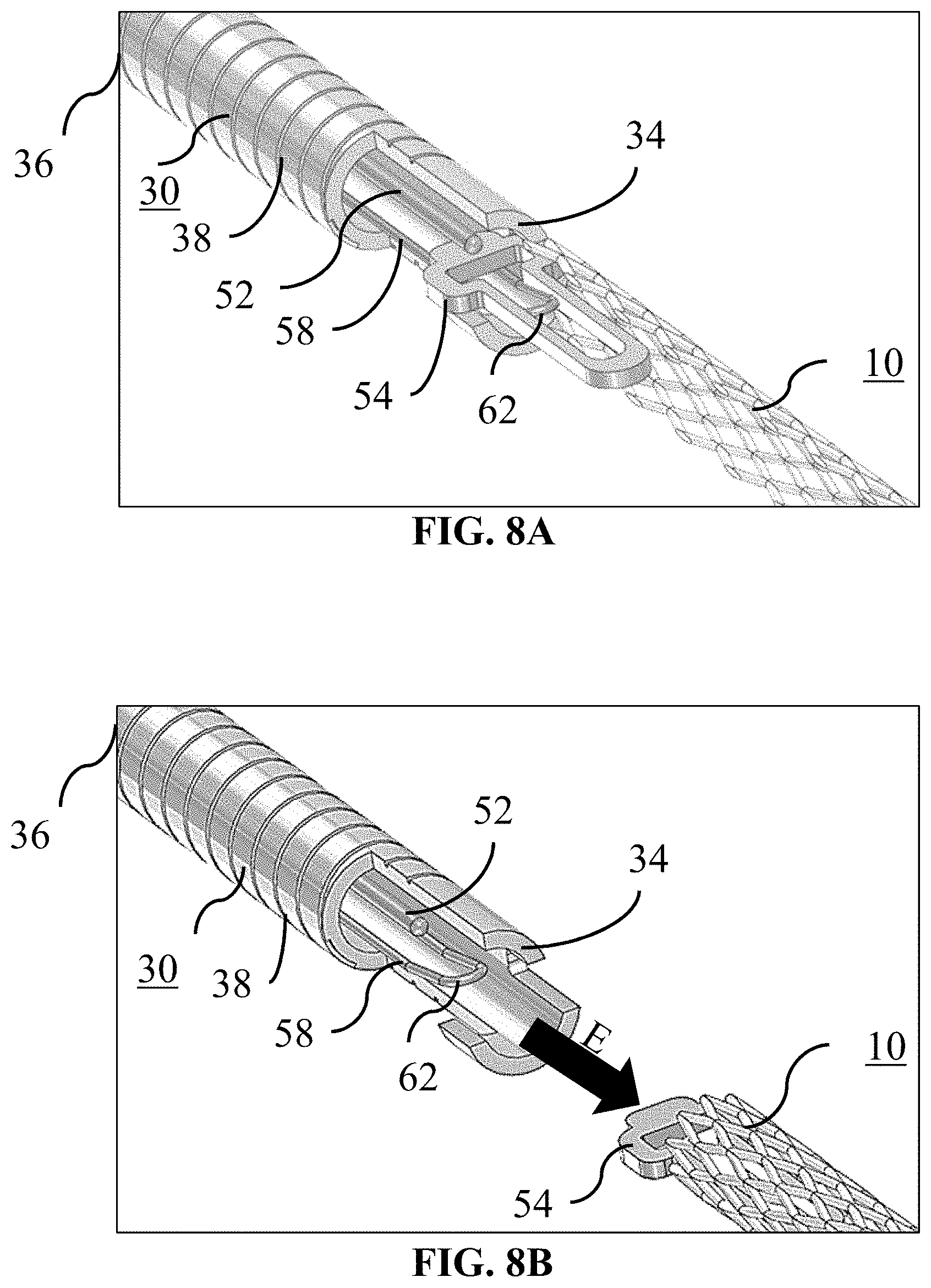
[0132] FIGS. 7A to 8B generally illustrate example attachment and delivery between delivery tube 30 and braid 10 for deploying and detaching braid 10 in aneurysm A. The embodiments of FIGS. 7A to 8B is merely one way that delivery tube 30 and braid 10 may be attached at end 34 and any number of attachment means are contemplated as needed or required. The delivery tube 30 as shown can have a lumen extending from a proximal end 36 to a distal, delivery end 34. FIG. 7A illustrates braid 10 engaged with the locking member 52 and loop wire 58 locked into the locking portion 54. The opening 60 of the loop wire 58 can be placed through the locking portion 54. The locking portion 54 preferably takes the form of a small diameter elongate filament, however, other forms such as wires or tubular structures are also suitable. While the locking portion 54 is preferably formed of nitinol, other metals and materials such as stainless steel, PTFE, nylon, ceramic or glass fiber and composites may also be suitable. Locking member 52, in one example, may be an elongated retractable fiber that may extend between ends 24 and 26 of the microcatheter 20. Locking member 52 preferably takes the form of a small diameter elongate filament, however, other forms such as wires or tubular structures are also suitable. While the locking member 52 is preferably formed of nitinol, other metals and materials such as stainless steel, PTFE, nylon, ceramic or glass fiber and composites may also be suitable. When the locking member 52 is put through the opening 60 the braid 10 is now secure. It is understood that delivery tube 30 may include a compressible portion 38 disposed between its ends 34 and 36.
[0133] The compressible portion 38 can allow the delivery tube 30 to bend and/or flex. Such flexibility can assist tracking the braid 10 through the microcatheter 20 and the tortuous path through the vasculature. The compressible portion 38 can be formed with interference spiral cuts that can allow for gaps to permit bending but in one example, do not act as a spiral-cut spring. Compressible portion 38 can be axially adjustable between an elongated condition and a compressed condition. However, any other arrangement allowing axial adjustment (e.g., a wound wire or spiral ribbon) can also be suitable for use with detachment systems according to the present disclosure). The compressible portion 38 can be in the elongated condition at rest and automatically or resiliently returns to the elongated condition from a compressed condition, unless otherwise constrained. The function of the compressible portion 38 is described in greater detail herein.
[0134] In FIG. 7A, a force F was previously applied to place the delivery tube 30 in a compressed state. FIG. 7B illustrates the locking member 52 being drawn proximally to begin the release sequence for braid 10. FIG. 8A illustrates the instant the locking member 52 exits the opening 60 and is pulled free of the loop wire 58. The distal end 62 of the loop wire 58 falls away/returns to its preformed shape and exits the locking portion 54. As can be seen, there is now nothing holding the braid 10 to the delivery tube 30. FIG. 8B illustrates the end of the release sequence. Here, the compressible portion 38 of the delivery tube 30 has expanded/returned to its original shape and "sprung" forward. An elastic force E is imparted by the distal end 34 of the delivery tube 30 to the braid 10 to "push" it away to insure a clean separation and delivery of the braid 10 to the aneurysm A. It is to be understood that the delivery scheme described in FIGS. 7A-8B are merely example approaches to delivery of braid 10.
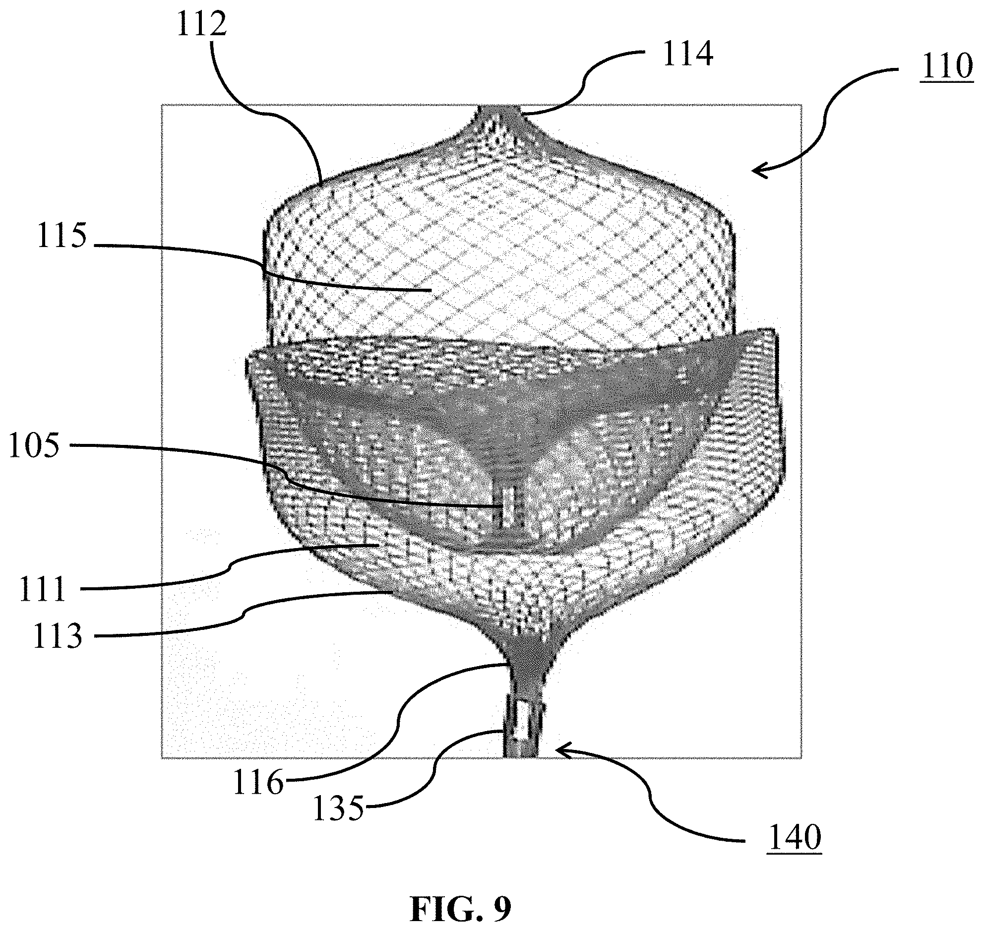
[0135] Turning to FIG. 9, an example braid 110 of this disclosure is shown still attached to example delivery system 140. The delivery system 140 is similar to the previously described system 40, meaning, it can include a microcatheter 20 with a delivery tube 30 slideably disposed therein. Braid 110 can be moved by delivery tube 30 from a collapsed state within microcatheter 20 to a deployed state distal of the microcatheter 20. A distal end 34 of delivery tube 30 may be attached to a proximal end 116.
[0136] In FIG. 10A, a distal segment 112 of braid 110 is shown having been deployed first to the dome of aneurysm A. Braid 110 can include a proximal expandable portion 113 that is capable of moving from a collapsed state within microcatheter 20 to a deployed state within the aneurysm A, as shown. Portion 112 is capable of moving from a collapsed state within the microcatheter 20 to a deployed state whereby the distal expandable portion 112 forms a distal sack 115 at least partially filling the aneurysm A. The sack 115 can partially or completely fill the aneurysm A in the deployed state.
[0137] In FIG. 10B, microcatheter 20 is withdrawn from aneurysm A causes portion 113 to form a proximal sack 111 that seals about the aneurysm neck. A junction 105 is disposed at a distal end of portion 113 with portion 112 distally connected thereof. Junction 105 can be a radiopaque band visible under fluoroscopy. Junction 105 in other examples can be formed from the braid itself to lower device profile. Once the proximal 113 and distal 112 expandable portions are in the deployed state, proximally translating portion 112 causes the proximal expandable portion 113 to move to an inverted configuration as more clearly seen in FIG. 11A.
[0138] FIG. 11B shows proximal portion 113 being adjusted for positioning at or adjacent the aneurysm neck by pulling on the braid 110 before detaching at junction 105. In so doing, portion 112 is capable of applying an outward force on portion 113 to anchor it in the aneurysm A and secure portion 113 against the aneurysm wall while supporting the aneurysm against compaction and compression. In some embodiments, portion 112 is deployed first into the aneurysm A to anchor against an aneurysm A wall. Portions 112 and 113 can be pressed together during heat set to make contacts. In some embodiments, once the proximal 113 and distal 112 portions are in the deployed state, proximally translating distal sack 115 causes proximal sack 113 to invert into itself. During this delivery, portion 113 can in some examples contact portion 112 causing a resistive force that facilitates inversion of portion 113.
[0139] After being inverted into itself, portion 113 is movable between positions at or adjacent neck N by proximally moving braid 110 before detaching from delivery system 140. In some embodiments, portion 113 is configured to form a dual layer bowl when inverted into itself, as in FIG. 11B. Portion 113 can be in turn made of a single heat shaped layer that is invertible into itself to form the dual layered bowl sealable at the neck N. The dual layer configuration of portion 113 can be capable of increasing metal coverage at or adjacent the neck N thereby promoting aneurysm embolization and flow diversion effect. In some examples, a porosity of portion 113 can be less than a porosity of the distal expandable portion 112.
[0140] FIG. 12A shows an example configuration with portion 112 including a dual layer braid configuration with one or more coils 135 contained therein. FIG. 12B is an enlarged schematic side view showing the configuration of FIG. 12A after detachment of braid 110 in the aneurysm A. Coils 135 can be connected to portion 112 and configured to pack or otherwise fill, fully or partially, during use. Coils 135 in some examples can be positionable within portion 112 in the deployed state. Coils 135 can also be positionable at least partially out of the braid 110 when delivered in the aneurysm A, such as in FIG. 13A. FIG. 13B is an enlarged schematic side view showing the braid configuration of FIG. 13A after detachment in the aneurysm A with a detachment marker 125 between detached, delivered braid 110 and microcatheter 20. As can be seen between FIGS. 13A-13B, once delivered in this configuration portion 113 can be inverted into portion 112 which can form the dual layer configuration. Braid 110 as shown can include an open or closed distal end 114 from which coils 135 may extent into the aneurysm A.
[0141] In place of a distal expanded segment in the aneurysm A of FIGS. 13A-13B, coils 135 are seen as being provided. A length of coils 135 can be adjusted in certain embodiments. During delivery, coils 135 can be first delivered to the aneurysm A and then portion 112 and portion 113. The examples of FIGS. 12A-13B, portion 113 can be constructed from of a single or dual layer braid, as needed or required.
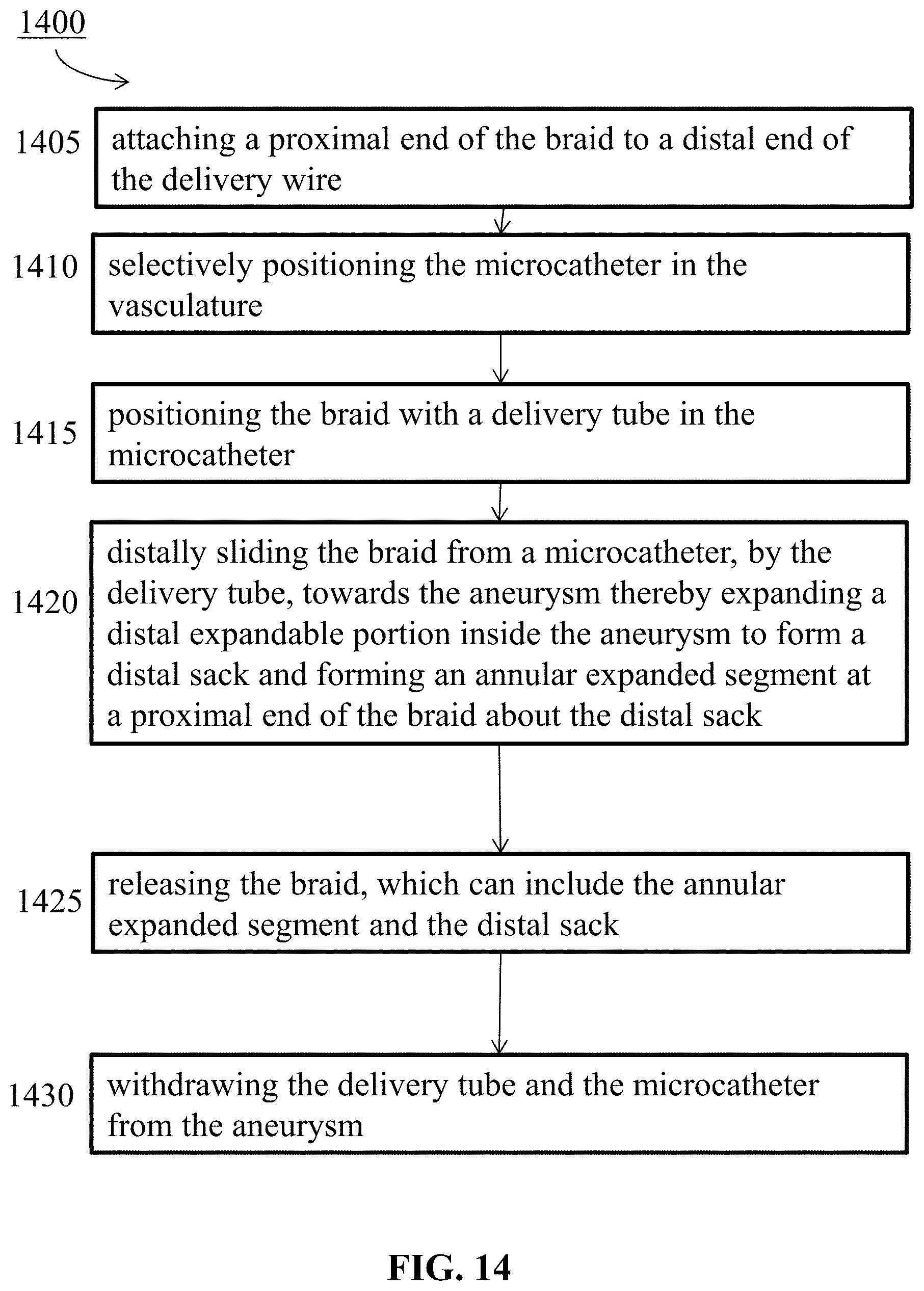
[0142] FIG. 14 is a flow diagram for a method 1400 of delivering an occlusive device to the aneurysm. Step 1405 includes attaching a proximal end of the braid to a distal end of a delivery tube. Step 1410 includes selectively positioning the microcatheter in the vasculature (e.g. at the neck of the aneurysm). Step 1415 includes positioning the braid with attached delivery tube in microcatheter. Step 1420 includes distally sliding the braid from a microcatheter, by the delivery tube, towards the aneurysm thereby expanding a distal expandable portion inside the aneurysm to form a distal sack and forming an annular expanded segment at a proximal end of the braid about the distal sack. Step 1425 includes releasing the braid, which can include the annular expanded segment and the distal sack. Step 1430 includes withdrawing the delivery tube and the microcatheter from the aneurysm.
[0143] In certain embodiments, the method 1400 can also include filling the aneurysm by forming the distal sack. In some embodiments, the selectively positioning of the braid comprises placing a distal end of the microcatheter at the neck of the aneurysm. In some embodiments, the distal expandable portion is simultaneously expanding when the annular expanded segment is forming.
[0144] In certain embodiments, the method 1400 can also include attaching the locking portion at the proximal end of the braid and the distal end of the delivery tube; and releasing, by the locking portion, the delivery tube from the braid. In certain embodiments, the method 1400 can also include expanding the annular expanded segment so that the annular expanded segment overlays an outer surface of the distal sack. In certain embodiments, the method 1400 includes pressing one or more outer ends of the distal sack against the annular expanded segment as the braid distally translates into the aneurysm. In certain embodiments, the method 1400 includes forming a gap or a cavity between the annular expanded segment and the distal sack when the annular expanded segment is inverted about the distal sack. In certain embodiments, the method 900 includes forming a tapered segment between the proximal and distal expandable portions.
[0145] In certain embodiments, the method 1400 also includes making a porosity of the proximal expandable portion less than a porosity of the tapered segment and/or the distal expandable portion; positioning the proximal expandable portion adjacent or in communication with a neck of the aneurysm; and deflecting, diverting, and/or slowing a flow into the aneurysm. The method 1400 can also include making a flexibility of the proximal expandable portion less than a flexibility of the tapered segment and/or the distal expandable portion; positioning the proximal expandable portion adjacent or in communication with a neck of the aneurysm; and deflecting, diverting, and/or slowing a flow into the aneurysm.
[0146] FIG. 15 is a flow diagram for a method 1500 of delivering an occlusive device to the aneurysm. In some embodiments, method 1500 is for using a braid for treating an aneurysm is disclosed. Step 1505 can include distally moving the braid into the aneurysm. Step 1510 can include expanding a proximal expandable portion of the braid from a collapsed state to an expanded state thereby sealing a neck of the aneurysm. Step 1515 can include expanding a distal expandable portion of the braid inside the aneurysm to form a distal sack thereby filling the aneurysm.
[0147] In certain embodiments, step 1515 can include forming an annular expanded segment at a proximal end of the braid about the distal sack. In some embodiments, the method 1500 can include overlaying and inverting the annular expanded segment about an outer surface of the distal sack. In some embodiments, the method 1500 can include forming a gap or a cavity between the annular expanded segment and the distal sack when the annular expanded segment inverts about the distal sack. In some embodiments, the method 1500 can include forming a tapered segment between the proximal and distal expandable portions. The method 1500 can also include making a porosity of the proximal expandable portion less than a porosity of the tapered segment and/or the distal expandable portion; and deflecting, diverting, and/or slowing a flow into the aneurysm. The method 1500 can also include making a flexibility of the proximal expandable portion less than a flexibility of the tapered segment and/or the distal expandable portion; and deflecting, diverting, and/or slowing a flow into the aneurysm.
[0148] FIG. 16 is a flow diagram for a method 1600 of delivering an occlusive device to an aneurysm. Step 1605 includes selectively positioning a braid in a vessel associated with the aneurysm, the braid including a proximal expandable portion capable of moving from a collapsed state within the microcatheter to a deployed state within the aneurysm. A junction can be disposed at a distal end of the proximal expandable portion. A distal expandable portion can be connected to the junction and distal of the proximal expandable portion, the distal expandable portion capable of moving from the collapsed state within the microcatheter to the deployed state at least partially filling the aneurysm. Step 1610 includes distally sliding the braid, by a delivery tube, from a microcatheter towards the aneurysm thereby at least partially filling the aneurysm by expanding the distal expandable portion inside the aneurysm to form a distal sack. Step 1615 includes anchoring the braid to the aneurysm by expanding the proximal expandable portion to form a proximal sack sealing about the neck of the aneurysm. Step 1620 includes proximally translating the distal sack causing the proximal sack to invert into itself.
[0149] It is understood that variations of the braid 10 can include various materials such as stainless steel, bio absorbable materials, and polymers. Braid 10, including any specific portions such as any breaks, varying regions of differing porosities, and occlusive sacks, can be heat set to various configurations such as spherical, oblong, saddle shaped, or the like, for shaping the distal sack and/or other expanded segment(s) to better match the aneurysm morphology. In addition, the braid 10 can be heat shaped to include weak points to facility the radial expansion of the distal sack and/or other expanded segment(s). Further, interstices of braid 10 that form the distal sack and/or other expanded segment(s) can vary, or be selectively designed, in size or shape along its length depending on how much braid 10 is caused to expand as delivery tube 30 is distally moved.
[0150] It is understood that the braid 10 can also be included in a system or otherwise in communication with an imaging device capable of imaging the distal sack and/or other expanded segment(s) of braid 10 with respect to the aneurysm. An orientation of the distal sack and/or other expanded segment(s) can be adjustable by the braid 10 being distally or proximally moved with respect to the aneurysm and monitored precisely by the imaging device through one or more radiopaque features of the braid or attached thereto.
[0151] The specific configurations, choice of materials and the size and shape of various elements can be varied according to particular design specifications or constraints requiring a system or method constructed according to the principles of the disclosed technology. Such changes are intended to be embraced within the scope of the disclosed technology. The presently disclosed embodiments, therefore, are considered in all respects to be illustrative and not restrictive. It will therefore be apparent from the foregoing that while particular forms of the disclosure have been illustrated and described, various modifications can be made without departing from the spirit and scope of the disclosure and all changes that come within the meaning and range of equivalents thereof are intended to be embraced therein.
* * * * *
D00000
D00001
D00002
D00003
D00004
D00005
D00006
D00007
D00008
D00009
D00010
D00011
D00012

D00013

D00014
D00015

D00016

XML
uspto.report is an independent third-party trademark research tool that is not affiliated, endorsed, or sponsored by the United States Patent and Trademark Office (USPTO) or any other governmental organization. The information provided by uspto.report is based on publicly available data at the time of writing and is intended for informational purposes only.
While we strive to provide accurate and up-to-date information, we do not guarantee the accuracy, completeness, reliability, or suitability of the information displayed on this site. The use of this site is at your own risk. Any reliance you place on such information is therefore strictly at your own risk.
All official trademark data, including owner information, should be verified by visiting the official USPTO website at www.uspto.gov. This site is not intended to replace professional legal advice and should not be used as a substitute for consulting with a legal professional who is knowledgeable about trademark law.