Impression Procedure
PERKINS; Rodney ; et al.
U.S. patent application number 16/405716 was filed with the patent office on 2020-02-27 for impression procedure. The applicant listed for this patent is EarLens Corporation. Invention is credited to Spencer CROY, Amanda FRENCH, Michelle M. INSERRA, Rodney PERKINS, James SILVER.
| Application Number | 20200068323 16/405716 |
| Document ID | / |
| Family ID | 62145669 |
| Filed Date | 2020-02-27 |


| United States Patent Application | 20200068323 |
| Kind Code | A1 |
| PERKINS; Rodney ; et al. | February 27, 2020 |
IMPRESSION PROCEDURE
Abstract
Improved methods are described for the creation of impressions for use in the manufacture of hearing aid components. In addition methods for manufacturing components of hearing aid systems using improved ear canal impressions are described.
| Inventors: | PERKINS; Rodney; (Woodside, CA) ; SILVER; James; (Palo Alto, CA) ; FRENCH; Amanda; (San Francisco, CA) ; CROY; Spencer; (San Francisco, CA) ; INSERRA; Michelle M.; (Mountain View, CA) | ||||||||||
| Applicant: |
|
||||||||||
|---|---|---|---|---|---|---|---|---|---|---|---|
| Family ID: | 62145669 | ||||||||||
| Appl. No.: | 16/405716 | ||||||||||
| Filed: | May 7, 2019 |
Related U.S. Patent Documents
| Application Number | Filing Date | Patent Number | ||
|---|---|---|---|---|
| PCT/US2017/061388 | Nov 13, 2017 | |||
| 16405716 | ||||
| 62564574 | Sep 28, 2017 | |||
| 62422535 | Nov 15, 2016 | |||
| Current U.S. Class: | 1/1 |
| Current CPC Class: | B29C 39/12 20130101; H04R 25/658 20130101; H04R 2225/77 20130101; H04R 25/652 20130101; B29C 39/10 20130101; H04R 25/606 20130101 |
| International Class: | H04R 25/00 20060101 H04R025/00 |
Claims
1. A method of creating a hearing system for a subject, the method comprising the steps of: taking a first impression of a first portion of an ear canal using an impression material having a first viscosity; taking a second impression of a second portion of the ear canal using an impression material having a second viscosity; digitally scanning the first impression to create a first digital model; digitally scanning the second impression to create a second digital model; merging the first digital model with the second digital model to create a merged model where the lateral portion of the merged model is comprised of at least a portion of the first digital model and the medial portion of the merged model is comprised of at least a portion of the second model; and using the merged digital model to manufacture at least one of an ear tip and a contact hearing device.
2. A method according to claim 1, further including the step of raising the subject from a supine position to an upright position prior to the step of taking a second impression.
3. A method according to claim 2, wherein the second impression is taken after the first impression is removed from the subject's ear canal.
4. A method according to claim 2, wherein the first impression is taken after the second impression is removed from the subject's ear canal.
5. A method according to claim 2, wherein the first impression is an impression of the subject's whole ear canal, including the tympanic membrane, bony canal and lateral end of the ear canal.
6. A method according to claim 2, wherein the first and second portions of the ear canal overlap.
7. A method according to claim 1, wherein the first viscosity is lower than the second viscosity.
8. A method of creating a hearing system for a subject, the method comprising the steps of: creating a hybrid impression of a subject's ear canal, the method of creating a hybrid impression comprising the steps of: injecting a low viscosity impression material into a first portion of the ear canal, wherein the low viscosity impression material is injected with the subject in a supine position; and injecting a high viscosity impression material into a second portion of the ear canal lateral to the first portion, wherein the high viscosity impression material is injected with the subject in an upright position; digitally scanning the hybrid impression to create a digital model of the subject's ear canal; and using the digital model to manufacture at least one of ear tip and a contact hearing device.
9. A method according to claim 8, wherein the viscosity of the low viscosity impression material is lower than the viscosity of the high viscosity impression material.
10. A method according to claim 8, further including the step of raising the subject from a supine position to an upright position prior to injecting the high viscosity impression material.
11. A method according to claim 10, wherein the subject is raised from a supine to an upright position after the low viscosity impression material has transitioned from a liquid to a gel state.
12. A method according to claim 11, wherein the subject is raised from a supine to an upright position before the low viscosity impression material is fully cured.
13. A method according to claim 9, wherein the step of raising the subject from a supine position to an upright position occurs at a predetermined time after the beginning of the step of injecting a low viscosity impression material.
14. A method according to claim 9, wherein the step of raising the subject from a supine position to an upright position occurs before the low viscosity impression material cures into a gel state.
15. A method according to claim 11, wherein the step of raising the subject from a supine position to an upright position occurs after the viscosity of the low viscosity impression material has increased to a viscosity where the low viscosity impression material no longer flows when subjected to gravitational forces.
16. A method according to claim 8, wherein the first and second portions of the ear canal do not overlap.
17. A method according to claim 8, wherein the low viscosity impression is bonded to the high viscosity impression.
18. A method of creating components of a hearing system for a subject, the method comprising the steps of: digitally scanning a first impression to create a first digital model, wherein the first impression is an impression of a first portion of an ear canal taken using a low viscosity impression material having a first viscosity and wherein the first impression has been taken with the subject in a supine position; digitally scanning a second impression to create a second digital model, wherein the second impression is an impression of a second portion of an ear canal taken using a high viscosity impression material having a second viscosity and wherein the second impression has been taken with the subject in an upright position; merging the first digital model with the second digital model to create a merged model where the medial portion of the merged model is comprised of the first digital model and the lateral portion of the merged model is comprised of the second model; using the merged digital model to manufacture at least one of an ear tip and a contact hearing device.
19. A method according to claim 18, wherein the first and second portions of the ear canal overlap.
20. A method according to claim 19, wherein the first and second digital models include digital models of the overlapping portions of the ear canal.
21. A method according to claim 19, wherein the merging step comprises aligning the digital models of the overlapping portions of ear canal.
22. A method according to claim 19, wherein the merging step comprises aligning points within the digital models of the overlapping portions of the ear canal.
23. A method according to claim 18, wherein the first impression is an impression of the subject's whole ear canal, including the tympanic membrane, bony canal and lateral end of the ear canal.
24. A method of creating components of a hearing system for a subject, the method comprising the steps of: digitally scanning a hybrid impression to create a digital model, wherein the hybrid impression has been created using a method comprising the steps of: injecting a low viscosity impression material into a first portion of the ear canal, wherein the low viscosity impression material is injected with the subject in a supine position; and injecting a high viscosity impression material into a second portion of the ear canal lateral to the first portion, wherein the high viscosity impression material is injected with the subject in an upright position; using the merged digital model to manufacture at least one of an ear tip and a contact hearing device.
25. A method according to claim 24, wherein the low viscosity impression material has an initial viscosity which is lower than the initial viscosity of the high viscosity material.
26. A method according to claim 25, wherein the low viscosity impression material is bonded to the high viscosity impression material to create the hybrid impression.
27. A kit comprising: a low viscosity material for use in making impressions of the medial end of a subject's ear canal; and a high viscosity material for use in making impressions of the lateral end of a subject's ear canal, wherein the initial viscosity of the low viscosity material is lower than the initial viscosity of the high viscosity material; and at least one dispenser adapted to dispense at least one of the low viscosity material or the high viscosity material.
28. A kit comprising: at least one impression dispensing gun; at least one dispenser of low viscosity impression material; at least one low viscosity impression material dispensing tip; at least one dispenser of high viscosity impression material; and at least one high viscosity impression material dispensing tip.
29. A kit according to claim 28, further comprising at least one dispenser of mineral oil.
30. A kit according to claim 29, further comprising at least one mineral oil basin.
31. A kit according to claim 30, further comprising at least one impression return box.
Description
CROSS-REFERENCE
[0001] This application is a continuation of PCT Application No. PCT/US2017/061388, filed Nov. 13, 2017, which claims the benefit of U.S. Provisional Application Nos. 62/564,574, filed Sep. 28, 2017, and 62/422,535, filed Nov. 15, 2016, which applications are incorporated herein by reference.
BACKGROUND OF THE INVENTION
[0002] Impressions are used in the hearing aid industry to provide models of the hearing aid user's ear canal. These impressions taken of the lateral end of the ear canal may be used to create ear tips (the portion of the hearing aid that fits into the lateral end of the ear canal) which conform to the actual shape of the user's ear canal. These custom ear tips generally provide better fit and comfort than ear tips which are not custom fitted to the customer's particular ear canal shape. In contact hearing aid systems which include hearing aid components (e.g., contact hearing devices) which are positioned on and conform to the shape of the user's tympanic membrane (ear drum), impressions may be taken that extend from the lateral end of the ear canal (e.g., near the pinna) to the medial end of the canal (e.g., at or near the tympanic membrane). These full canal impressions may be used to manufacture both custom ear tips and custom contact hearing aid components, such as contact hearing devices, for the user's tympanic membrane. The methods of taking these full canal impressions, along with the characteristics of the materials used to take the impressions will have an impact on the overall fit, comfort and utility of the components manufactured using that full impression. As used herein, ear tip may refer to a conventional hearing aid ear tip (e.g., including a receiver) or to a light tip which may be a component of a contact hearing system.
BRIEF DESCRIPTION OF THE DRAWINGS
[0003] The foregoing and other objects, features and advantages of embodiments of the present inventive concepts will be apparent from the more particular description of preferred embodiments, as illustrated in the accompanying drawings in which like reference characters refer to the same or like elements. The drawings are not necessarily to scale, emphasis instead being placed upon illustrating the principles of the preferred embodiments.
[0004] FIG. 1 illustrates an impression being taken with the subject in a supine position and a health care professional injecting the impression material into the subject's ear canal.
[0005] FIG. 2 illustrates an impression being taken with the subject in an upright position and a health care professional injecting the impression material into the subject's ear canal.
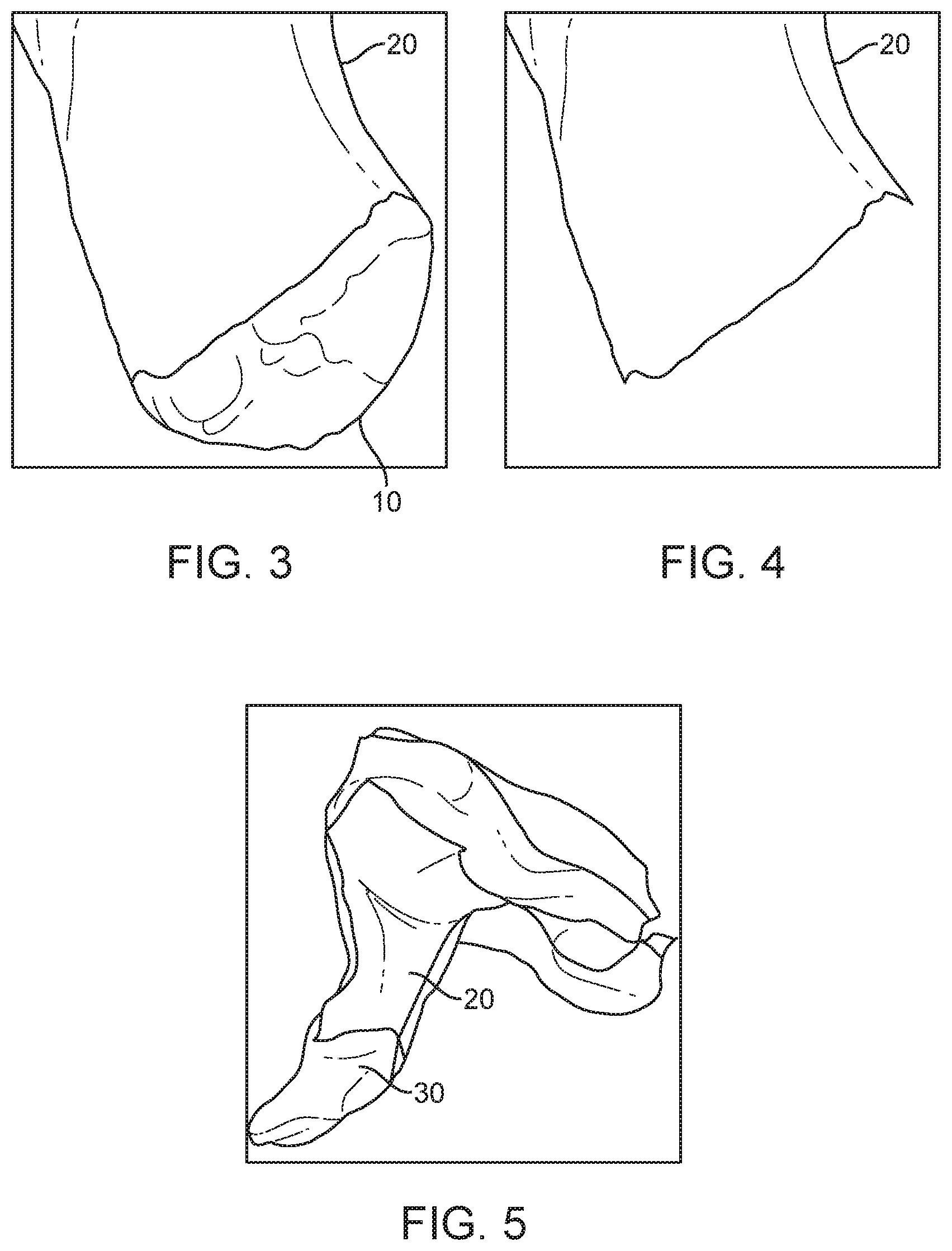
[0006] FIG. 3 illustrates a scanned image of the medial end of a lateral ear canal impression.
[0007] FIG. 4 illustrates a scanned image of a lateral ear canal impression with a portion of the medial end removed.
[0008] FIG. 5 illustrates a scanned image of a lateral ear canal impression overlaid over a scanned image of a full canal impression.
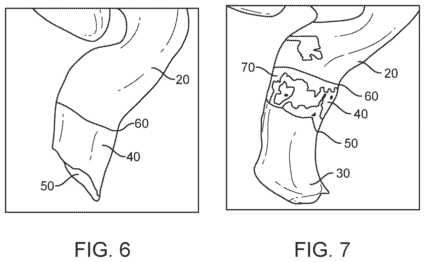
[0009] FIG. 6 illustrates a digital model of a lateral impression including an overlapping region.
[0010] FIG. 7 illustrates a digital model of a combined medial and lateral impression, including an overlapping region.
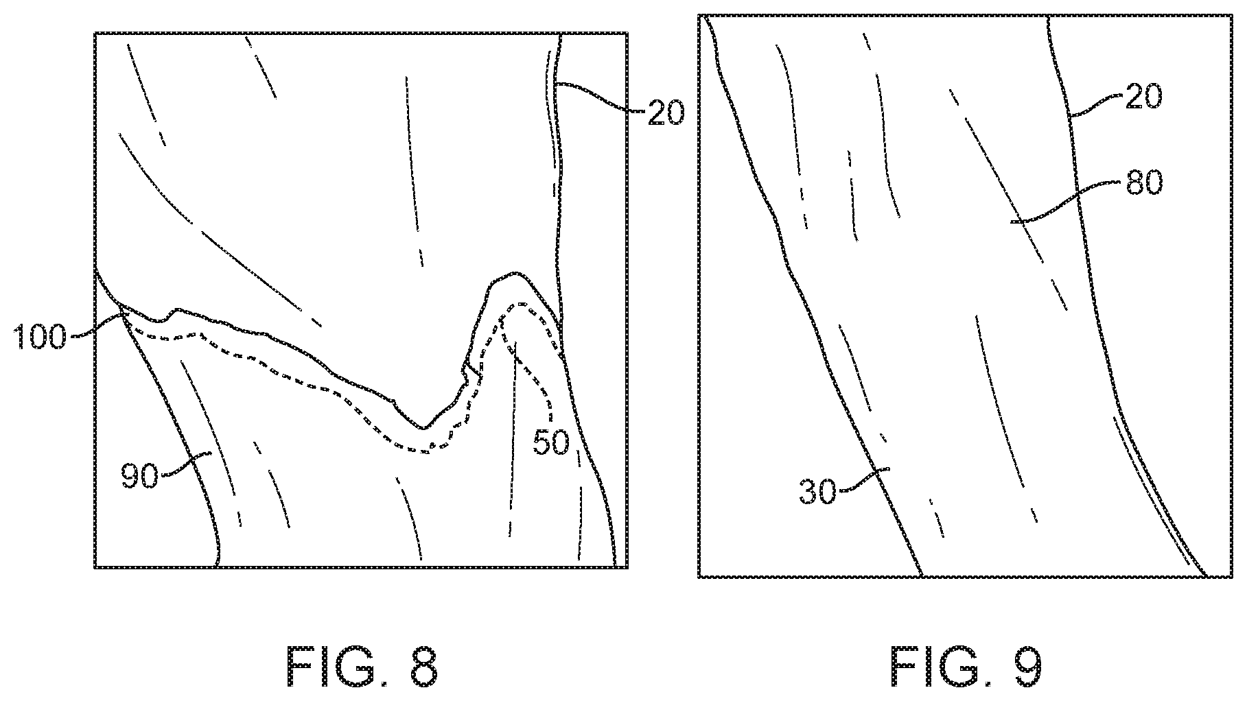
[0011] FIG. 8 illustrates a digital model of a combined medial and lateral impression, including a junction.
[0012] FIG. 9 illustrates a digital model of a combined medial and lateral impression after the junction has been smoothed.
[0013] FIG. 10 illustrates an impression kit according to one embodiment of the present invention.
DETAILED DESCRIPTION OF THE INVENTION
[0014] FIG. 1 illustrates an impression being taken with the subject in a supine position and a health care professional 190 injecting the impression material into the subject's ear canal. In one embodiment of the invention, two different impressions are taken and digitally scanned. In this embodiment, the different impressions represent two different (although overlapping) portions of the ear canal anatomy and are made using two different viscosities of impression material. In this embodiment, the first impression (Impression 1) may be either: a) an impression of the whole ear canal, down to and including the tympanic membrane or b) an impression of the medial portion of the ear canal from approximately the beginning of the bony canal to and including the tympanic membrane. The Impression 1 impressions may be made using a low viscosity impression material with the subject lying in a supine position (the supine position is chosen to prevent the low viscosity impression material from running out of the subject's ear before it cures). The use of a low viscosity material for Impression 1 enables the impression to reflect the fine detail of the anatomy of the medial ear canal since it flows easily into all areas of the medial ear canal.
[0015] FIG. 2 illustrates an impression being taken with the subject in an upright position and a health care professional 190 injecting the impression material into the subject's ear canal. In embodiments of the invention, the second impression (Impression 2) is an impression of the lateral portion of the ear canal wherein the impression extends from a point in the subject's bony canal (but not as deep as the tympanic membrane) to the subject's concha bowl. Impression 2 is made using a high viscosity material with the subject in an upright (sitting) position to obtain an impression of the lateral ear canal which is most representative of the shape of the ear canal when the subject is in the position where he/she is most likely to be when using the hearing aids (e.g., sitting or standing). As the impression material cures, the high viscosity material exerts pressure on the tissue in the lateral ear canal, causing slight compression of the tissue in the lateral ear canal, thus creating an ear tip which fits snugly into the lateral ear canal and will not migrate out of the ear canal. The pressure is created by the viscosity of the high viscosity impression material and the force it exerts on the ear canal.
[0016] In one embodiment of the invention, once the impressions are made they may be shipped back to the manufacturer where they are cleaned and placed into a digital scanner. The digital scanner is used to make digital models of the impressions, which digital models may be representative of all or sections of the subject's ear canal. Where Impression 1 is an impression of the whole ear canal, down to and including the tympanic membrane, the output of the scanner for Impression 1 is a digital model of the full ear canal which includes a medial portion representative of the shape, size and surface structure of the entire ear canal, including the medial portion, tympanic membrane and sulcus region. Where Impression 1 is an impression of the medial end of the ear canal, down to and including the tympanic membrane, the output of the scanner for Impression 1 is a digital model of the medial end of the ear canal representative of the shape, size and surface structure of the tympanic membrane and sulcus region. The output of the scanner for Impression 2 is a digital model which includes a first portion representative of the shape, size and surface structure of the lateral end of the ear canal and may also include a second portion representing a medial end of Impression 2.
[0017] Once Impression 1 and Impression 2 are complete, and have been scanned using, for example, a digital scanner, digital representations of Impression 1 and Impression 2 are created. The resulting scans are combined by the technique described below to create a single digital representation of the ear canal of the subject, including digital features representative of the surface of the subject's ear canal. The resulting digital representation will represent the subject's ear canal from the concha bowl to the tympanic membrane. This single digital representation combines the representation resulting from the use of a high viscosity impression material to create a model of the lateral ear canal (higher pressure conforms to soft tissue of lateral ear canal) and the representation resulting from the use of a low viscosity impression material to create a model of the medial portion of the ear canal (lower viscosity allows it to flow evenly into the farthest reaches of the ear canal without creating bubbles or missing areas which might ruin the impression and make it difficult to create a resulting product). The low viscosity impression material further allows the impression to capture the fine detail of the tympanic membrane and sulcus region.
[0018] As illustrated in FIGS. 3 and 4, once the scans are completed, the digital model (scan) of Impression 2 may be "cleaned up" (i.e., digitally altered) to, for example, remove data which is not representative of the anatomy of the subject. This extraneous data may result from impression material at the medial end of the impression which did not contact any portion of the ear canal. In the digital model, this additional data, which is not representative of the actual shape of the subject's ear canal be referred to as noise. See, for example, the portion of digital model 20 labeled 10 in FIG. 3, this portion of digital model 20 has been removed in FIG. 4.
[0019] Once the extraneous data is removed from digital model 2, the corresponding portions of the data files for models 1 and 2 may be overlaid to obtain a best fit alignment for the overall impressions. This best fit analysis may be performed either manually or electronically. In either case, the two models are overlaid and the features are used to get a best fit alignment. See, for example, FIG. 5 where digital model 20 of the medial end of the subject's ear canal is overlaid over digital model 30 of the entire ear canal of the subject. In FIG. 5, the two digital models are manipulated until the corresponding alignment regions of digital model 20 and digital model 30 align as closely as possible. The required manipulation may be done either manually or using alignment algorithms.
[0020] Once digital models 20 and 30 are in rough alignment, an alignment region 40 may be identified on digital model 20 as illustrated in FIG. 6. The alignment region 40 generally extends from the medial end 50 of digital model 20 to a starting point 60 representative of a predefined portion of the bony canal of the subject, which may be, for example, the beginning of the bony canal. The starting point 60 for the alignment region 40 may, alternatively, be defined with respect to other features of the ear canal, such as, for example, being defined as medial to the second bend. In FIG. 6, alignment region 40 extends from starting point 60 to medial end 50 of digital model 20. The bony canal is selected as alignment region 40 because it is an area where the two digital scans overlap. In addition the bony canal is the region of the ear canal least subject to changes in shape resulting from body position and/or pressure from the impression material, particularly the high viscosity impression material resulting from the curing process. The bony canal region is, therefore, believed to be the region in which the two digital models are most likely to be identical and/or similar enough to enable the two digital scans to be aligned. Thus, the alignment region is likely to be substantially the same in digital model 20 and digital model 30.
[0021] Once the alignment region 40 is defined in digital model 20, the alignment region 40 may be locally aligned with the bony canal region 70 of digital model 30 as illustrated in FIG. 7. In embodiments of the invention, the alignment region 40 may be on the order of approximately 3 millimeters. Once the alignment region 40 is fully aligned with bony canal region 70, the portion of digital model 20 which is medial to medial end 50 of digital model 30 is deleted. In embodiments of the invention, a small additional portion of digital model 30 is also deleted, leaving a small gap 100 as illustrated in FIG. 8. In FIG. 9, gap 100 is filled and smoothed to create a complete digital model 80 which incorporates data from digital model 20 as representative of the lateral ear canal and which incorporates data from digital model 30 as representative of the medial ear canal. This combined digital model 80 impression may then be used to design components which reside in the ear canal, such components may include ear tips, light tips, contact hearing devices, tympanic lenses and/or other components of contact hearing systems.
[0022] In alternative embodiments of the invention, complete digital model 80 may be made from a hybrid impression wherein the low viscosity impression material is first poured into the subject's ear canal, followed by the high viscosity impression material to create a single impression capturing the ear canal of the subject from the tympanic membrane to the concha bowl.
[0023] In alternative embodiments of the invention, the low viscosity impression may be left to fully cure while the subject is supine before moving the subject to an upright position and adding the high viscosity impression material. In this embodiment the low viscosity impression material may be used as an oto-block that prevents the high viscosity impression material from contacting the tympanic membrane and/or the medial end of the subject's ear canal.
[0024] In embodiments of the invention, the high viscosity impression material is bonded to the low viscosity impression material prior to removing the hybrid impression from the subject's ear canal.
[0025] In embodiments of the invention, one method of taking a hybrid impression of the ear canal of a hearing aid subject involves generating an impression using two separate materials through a predetermined series of steps, including ensuring that elements of the method are performed at predetermined time intervals. In embodiments of the invention, the predetermined time intervals may be determined as a function of characteristics of the impression material being used. In embodiments of the invention, such characteristics may include, for example, the curing time of the impression material. In embodiments of the invention, such characteristics may include, for example, the viscosity of the impression material.
[0026] In embodiments of the invention, the method may include the step of raising the subject from a supine to a sitting (or standing) position at a predetermined time or after a predetermined event has occurred, for example within a predetermined interval after initially depositing impression material in the ear canal of the subject. Embodiments of the invention, which include the forgoing step, may be referred to as Seated Hybrid Impressions. In embodiments of the invention, the time interval may be calculated such that the subject is raised before the impression material used in the supine position is fully cured. In embodiments of the invention, the time interval may be calculated such that the subject is raised after the impression material used when the subject is in the supine position has cured to a point where it is sufficiently viscous that it does not flow out of the ear canal. In embodiments of the invention, the timing of raising the subject from a supine position into an upright position is dependent upon the timing of the transition of the impression material from a viscous material to a gel. In embodiments of the invention, a sol to gel transition, in which the material is transformed from what is technically a liquid (sol) into a solid (gel) is the preferred point for raising the subject from a supine to an upright position. In embodiments of the invention, it may be possible to raise the subject before the impression material transitions from a liquid to a solid. For example, the subject may be raised when the impression material's viscosity increases enough to prevent the impression material from flowing out of the ear when the subject is raised to the upright position.
[0027] In embodiments of the invention, materials which are suitable for creating impressions of the medial end of the ear canal include materials which initially have a low viscosity, such as, for example, a viscosity of less than 10 centipoise ("cPs") and/or a viscosity of between approximately 10 cPs and 20,000 cPs. Impression materials suitable for use in low viscosity applications of the present invention may be referred to herein as Low Viscosity Impression Materials or LVIM. In embodiments of the invention, materials suitable for use as an LVIM may have a hardness of approximately 15.+-.2 Shore A. In embodiments of the invention, materials suitable for use as an LVIM may have an Elongation at break of greater than approximately 250%. In embodiments of the invention, the viscosity values set forth above represent the viscosity of the impression material as it is initially deposited in the ear canal of the subject using, for example impression dispensing gun 110. In embodiments of the invention, wherein the impression material is a two part material which is mixed prior to injecting it into the subject's ear canal, the viscosity values set forth above represent the viscosity of the impression material immediately following the mixing of the two materials which comprise the two part impression material.
[0028] In embodiments of the invention, materials which are suitable for creating impressions of the lateral end of the ear canal include materials which have a higher viscosity than the Low Viscosity Impression Materials, such as, for example, a viscosity of more than 100 cPs and/or a viscosity of between approximately 100 and 100,000 cPs. Impression materials suitable for use in high viscosity applications of the present invention may be referred to herein as High Viscosity Impression Materials or HVIM. In embodiments of the invention, materials suitable for use as an HVIM may have a hardness of approximately 30.+-.3 Shore A. In embodiments of the invention, materials suitable for use as a HVIM may include Otoform A softX having a hardness of approximately 25+/-2 Shore A.
[0029] In embodiments of the invention, materials suitable for creating impressions may include two-part, platinum cure silicones. Once the two components of the impression materials are mixed together, these materials increase in viscosity over time and ultimately cure into a solid material. After a period of time, the material undergoes what is known as a sol-gel transition, in which the material is transformed from a liquid state (sol) to a soft, solid state (gel). The gel may continue to cross-link (or cure) over time so that it becomes harder than the gel, and eventually is fully cured. The fully cured material will not undergo any shape change when it is released from a physical constraint, such as when it is removed from an ear canal. Instead, the fully cured material retains the geometry it had when it transitioned from a gel to a fully cured solid.
[0030] In embodiments of the invention, factors which can affect the timing of moving a subject from a supine to an upright position while making an impression of the subject's ear canal include: i) the temperature of the impression materials (higher temperatures result in faster cures); ii) the ratio of the two components comprising the impression material (1:1, 2:1, or other ratios); iii) the initial concentration of platinum catalyst; and iv) the presence of any inhibitors of the platinum catalyst (such as alcohols, amine-containing chemicals, sulfur-containing chemicals or materials, and phosphorous-containing chemicals, among others). For example, certain HVIM materials cure faster than the LVIM materials, with the former reaching a gel state in about 1 minute, while the latter reaches a gel state in about 2 minutes at normal body temperature.
[0031] In embodiments of the invention, the method may use a serial procedure to gather a full seated Hybrid Impression from one ear before moving to the second ear. Alternatively, a health care professional may inject the LVIM materials into both ear canals of the subject before moving the subject from a supine to an upright position. In an embodiment of the invention, the health care professional may alternate between the right and left ears, for example, injecting LVIM in the left ear followed by HVIM in that ear, followed by LVIM in the right ear and then HVIM in the right ear. In embodiments of the invention, the patient may move from a sitting position to a supine position after injecting the first HVIM material but before it is fully cured.
[0032] In embodiments of the invention, the following steps may be used to create a Seated Hybrid Impression. The steps include: [0033] 1. The step of reclining the subject into a supine position, putting Low Viscosity Impression Materials into the subject's ear such that the LVIM extends into the medial end of the subject's ear canal. In embodiments of the invention, the physician will continue to put LVIM into the ear canal of the supine subject until the LVIM reaches a predetermined region of the subject's ear canal. In embodiments of the invention, the predetermined region may be the subject's Cartilaginous Boney Junction ("CBJ"). In embodiments of the invention, the predetermined region may be a point just beyond the subject's CBJ. In embodiments of the invention, the predetermined region may be the region designated as the lateral smooth glandular tissue area. In embodiments of the invention, the predetermined region may be the medial end of the second bend in the subject's ear canal. In embodiments of the invention, the physician may continue to put LVIM into the subject's ear canal until the LVIM material is far enough lateral to allow the injection tool for the HVIM to reach the lateral end of the LVIM material. In embodiments of the invention, the injection of LVIM must be completed within a first predetermined period of time. In embodiments of the invention, the first predetermined period of time may be the time required for the LVIM to increase in viscosity such that it will no longer flow out of the subject's ear canal. In embodiments of the invention, the first predetermined period of time may be less than the time required for the LVIM to fully harden or cure. In embodiments of the invention, the first predetermined period of time may be approximately one minute and 15 seconds following the initial mixing of LVIM material for deposition in the subject's ear canal. In embodiments of the invention, the LVIM material is a 2 part material which only begins to cure after the two parts are mixed together. In embodiments of the invention where the deposition of LVIM takes less than the first predetermined period of time, the subject may be maintained in the supine position until the end of the first predetermined period of time. In embodiments of the invention, the subject may be raised to an upright position just after the LVIM transitions from a viscous liquid to a gel but before it fully cures. In embodiments of the invention, the subject may be raised into an upright position before the LVIM gel fully cures. [0034] 2. The step of moving the subject into an upright (e.g., sitting or standing) position and allowing the LVIM material to fully harden or cure. In embodiments of the invention, the subject may be moved into an upright position after the end of the first predetermined period of time. In embodiments of the invention, the subject must be fully upright by the end of a second predetermined period of time where in the second predetermined period of time may be measured from the initial mixing of the LVIM prior to dispensing in the subject's ear canal. In embodiments of the invention, the second predetermined period of time, as measured from the initial dispensing of the LVIM in the subject's ear may be from approximately one minute and thirty seconds to two minutes and thirty seconds. [0035] 3. The step of injecting HVIM into the subject's ear canal. In embodiments of the invention, once the subject is in an upright position, HVIM material may be injected into the ear canal, starting at the lateral end of the LVIM impression material and working out to the end of the ear canal. In the embodiments of the invention, HVIM material may extend into the concha bowl of the subject. In embodiments of the invention, the HVIM material may extend to the level of the subject's scapha. In embodiments of the invention, the HVIM material may extend far enough to cover the subject's tragus. [0036] 4. The step of curing the HVIM material. In embodiments of the invention, the HVIM material may then be allowed to cure. [0037] a. Once the LVIM material is fully cured, the next step of the method may be to leave the first impression in the subject's ear, and take an impression of the subject's other ear using the steps set forth above. [0038] 5. The step of removing the hybrid impression from the subject's ear. In embodiments of the invention, both the LVIM and HVIM material may then be allowed to cure before removing the fully cured hybrid impression from the subject's ear. In embodiments of the invention, the process of fully curing the LVIM and HVIM material may take approximately eight minutes from the time the initial LVIM material was injected into the subject's ear canal. In embodiments of the invention, the physician may wait for a period of more than approximately eight minutes from the initial injection of the LVIM material to remove the hybrid impression from the subject's ear. [0039] a. If they have not already done so, once the hybrid impression has been removed from the subject's first ear, the physician may use the steps outlined above to take an impression of the subject's second ear.
[0040] In embodiments of the invention, the procedure described herein may be augmented by applying a cap of HVIM material over the LVIM material prior to moving the subject into an upright position as described in Step 2 above. In embodiments of the invention, the cap of HVIM material may be less than the full HVIM impression. In embodiments of the invention, the cap of HVIM material may be small enough to leave room in the subject's ear canal for additional HVIM material once the subject has been raised to the upright position. In embodiments of the invention, the cap of HVIM material may be approximately 3 millimeters to 20 millimeters thick.
[0041] The following timeline is illustrative of the timing of various steps of the sitting hybrid impression process according to one embodiment of the present invention. Sample Impression Timeline:
TABLE-US-00001 Impression Method Hybrid Total Time (min:sec) 13:15 0:15 0:30 0:45 1:00 1:15 1:30 1:45 2:00 2:15 Capture LVIM, Ear 1 Sit Capture HVIM, (75 Sec) (15 Sec) Ear 1 (30 Sec) 2:30 2:45 3:00 3:15 3:30 3:45 4:00 4:15 4:30 HVIM Cure, Ear 1 (150 Sec) 4:45 5:00 5:15 5:30 5:45 6:00 6:15 6:30 6:45 Recline Capture LVIM, Ear 2 Sit Capture HVIM, (15 Sec) (75 Sec) (15 Sec) Ear 2 (30 Sec) 7:00 7:15 7:30 7:45 8:00 8:15 8:30 8:45 9:00 HVIM + LVIM Cure (6 min, 30 Sec) 9:15 9:30 9:45 10:00 10:15 10:30 10:45 11:00 11:15 HVIM + LVIM Cure (6 min, 30 Sec) 11:30 11:45 12:00 12:15 12:30 12:45 13:00 13:15 HVIM + LVIM Cure (6 min, 30 Sec)
[0042] In embodiments of the invention, the method may include placing the subject in a supine position and injecting LVIM into the subject's ear using enough LVIM to reach a predetermined point in the subject's ear canal. The subject would then remain in the supine position for approximately one minute and fifteen seconds before being moved to an upright position (e.g., sitting or standing). Approximately one minute and forty-five seconds later, the health care professional would inject HVIM into the subject's ear canal, using enough HVIM material to fill the ear canal to at least a point where the HVIM would be visible at the ear canal opening. In embodiments of the invention, the HVIM may be used to fill the ear canal to the Concha Cymba. In embodiments of the invention, the HVIM may be used to fill the ear canal to the concha bowl. In embodiments of the invention, the hybrid impression (including both the LVIM and HVIM) would be pulled from the subject's ear canal once the combined impression has bonded and fully cured.
[0043] In embodiments of the invention the low viscosity impression material may be a material particularly suited to making medial impressions. The LVIM may be Formasil AB (available from Dreve, Unna, Germany). The LVIM may be a low viscosity, two-part platinum cure silicone. The LVIM may have a viscosity which is sufficiently low, prior to mixing (approximately 1 to 1000 cPs), to ensure that it flows easily into the sulcus region and covers the tympanic membrane when it is injected into the ear canal of a subject. The LVIM may be selected to set up quickly. The LVIM may be selected to have a sol-gel transition time at 37.degree. C. of approximately 1 to 3 minutes. The LVIM may be selected such that it becomes fully cured within 5 minutes of being injected into the ear canal of a subject. The LVIM may be selected to be a soft material, with a durometer of approximately 15.+-.2 Shore A and a tensile strength of greater than approximately 1 MPa. The LVIM may be selected to have an excellent elastic recovery, such as an elastic recovery which is greater than approximately 99%.
[0044] In embodiments of the invention, the high viscosity impression material may be particularly suited to making lateral impressions. The HVIM may be Otoform A softX (available from Dreve, Unna, Germany). The HVIM may have a relatively high viscosity. The HVIM may be a two-part platinum cure silicone. The HVIM may have a viscosity prior to mixing of approximately 1,000 to approximately 100,000 cPs. The HVIM may be selected to have a viscosity which limits its ability to flow all the way down to the sulcus region, making it suitable for use in the outer, more lateral, portion of the subject's ear canal. The HVIM may be selected to set up faster than the LVIM. The HVIM may have a sol-gel transition time at 37.degree. C. of approximately 30 seconds to approximately 1 minute. The HVIM may be selected to fully cure within approximately 4 minutes. The HVIM may be selected to be less soft than the LVIM. The HVIM may be selected to have a durometer of approximately 25.+-.2 Shore A after complete curing. The HVIM may be selected to have an elastic recovery of greater than approximately 99%.
[0045] In one embodiment, the present invention is directed to a method of creating a hearing system for a subject, the method including the steps of: taking a first impression of a first portion of an ear canal using an impression material having a first viscosity; taking a second impression of a second portion of the ear canal using an impression material having a second viscosity; digitally scanning the first impression to create a first digital model; digitally scanning the second impression to create a second digital model; merging the first digital model with the second digital model to create a merged model where the lateral portion of the merged model is comprised of at least a portion of the first digital model and the medial portion of the merged model is comprised of at least a portion of the second model; and, using the merged digital model to manufacture at least one of an ear tip and a contact hearing device. In further embodiments of the invention, the method may include the step of raising the subject from a supine position to an upright position prior to the step of taking a second impression. In further embodiments of the invention, the second impression may be taken after the first impression is removed from the subject's ear canal. In further embodiments of the invention, the first impression may be taken after the second impression is removed from the subject's ear canal. In further embodiments of the invention, the first impression is an impression of the subject's whole ear canal, including the tympanic membrane, bony canal and lateral end of the ear canal. In further embodiments of the invention, the first and second portions of the ear canal overlap. In further embodiments of the invention, the first viscosity is lower than the second viscosity.
[0046] In one embodiment, the present invention is directed to a method of creating a hearing system for a subject, the method including the steps of: creating a hybrid impression of a subject's ear canal, the method of creating a hybrid impression including the steps of: injecting a low viscosity impression material into a first portion of the ear canal, wherein the low viscosity impression material is injected with the subject in a supine position; and, injecting a high viscosity impression material into a second portion of the ear canal lateral to the first portion, wherein the high viscosity impression material is injected with the subject in an upright position; digitally scanning the hybrid impression to create a digital model of the subject's ear canal; and, using the digital model to manufacture at least one of ear tip and a contact hearing device. In further embodiments of the invention, the initial viscosity of the low viscosity impression material is lower than the initial viscosity of the high viscosity impression material. In further embodiments of the invention, the method further includes the step of raising the subject from a supine position to an upright position prior to injecting the high viscosity impression material. In further embodiments of the invention, the subject is raised from a supine to an upright position after the low viscosity impression material has transitioned from a liquid to a gel state. In further embodiments of the invention, the subject is raised from a supine to an upright position before the low viscosity impression material is fully cured. In further embodiments of the invention, the step of raising the subject from a supine position to an upright position occurs at a predetermined time after the beginning of the step of injecting a low viscosity impression material. In further embodiments of the invention, the step of raising the subject from a supine position to an upright position occurs before the low viscosity impression material cures into a gel state. In further embodiments of the invention, the step of raising the subject from a supine position to an upright position occurs after the viscosity of the low viscosity impression material has increased to a viscosity where the low viscosity impression material no longer flows when subjected to gravitational forces. In further embodiments of the invention, the first and second portions of the ear canal do not overlap. In further embodiments of the invention the low viscosity impression is bonded to the high viscosity impression.
[0047] In one embodiment, the present invention is directed to a method of creating components of a hearing system for a subject, the method including the steps of: digitally scanning a first impression to create a first digital model, wherein the first impression is an impression of a first portion of an ear canal taken using a low viscosity impression material having a first viscosity and wherein the first impression has been taken with the subject in a supine position; digitally scanning a second impression to create a second digital model, wherein the second impression is an impression of a second portion of an ear canal taken using a high viscosity impression material having a second viscosity, and wherein the second impression has been taken with the subject in an upright position; merging the first digital model with the second digital model to create a merged model where the medial portion of the merged model is comprised of the first digital model and the lateral portion of the merged model is comprised of the second model; using the merged digital model to manufacture at least one of an ear tip and a contact hearing device. In further embodiments of the invention, the first and second portions of the ear canal overlap. In further embodiments of the invention, the first and second digital models include digital models of the overlapping portions of the ear canal. In further embodiments of the invention, the merging step includes aligning the digital models of the overlapping portions of ear canal. In further embodiments of the invention, the merging step includes aligning points within the digital models of the overlapping portions of the ear canal. In further embodiments of the invention, the first impression is an impression of the subject's whole ear canal, including the tympanic membrane, bony canal and lateral end of the ear canal.
[0048] In one embodiment, the present invention is directed to a method of creating components of a hearing system for a subject, the method including the steps of: digitally scanning a hybrid impression to create a digital model, wherein the hybrid impression has been created using a method including the steps of: injecting a low viscosity impression material into a first portion of the ear canal, wherein the low viscosity impression material is injected with the subject in a supine position; and, injecting a high viscosity impression material into a second portion of the ear canal lateral to the first portion, wherein the high viscosity impression material is injected with the subject in an upright position; using the merged digital model to manufacture at least one of an ear tip and a contact hearing device. In further embodiments of the invention, the low viscosity impression material has an initial viscosity which is lower than the initial viscosity of the high viscosity material. In further embodiments of the invention, the low viscosity impression material is bonded to the high viscosity impression material to create the hybrid impression.
[0049] In one embodiment the present invention is directed to a kit including: a low viscosity material for use in making impressions of the medial end of a subject's ear canal; and, a high viscosity material for use in making impressions of the lateral end of a subject's ear canal, wherein the initial viscosity of the low viscosity material is lower than the initial viscosity of the high viscosity material; and, at least one dispenser adapted to dispense at least one of the low viscosity material or the high viscosity material.
[0050] In one embodiment, the present invention is directed to a kit including: at least one impression dispensing gun; at least one dispenser of low viscosity impression material; at least one low viscosity impression material dispensing tip; at least one dispenser of high viscosity impression material; and, at least one high viscosity impression material dispensing tip. In further embodiments of the invention, the kit further includes at least one dispenser of mineral oil. In further embodiments of the invention, the kit further includes at least one mineral oil basin. In further embodiments of the invention, the kit further includes at least one impression return box.
[0051] Embodiments of the invention may include a kit useful in practicing the methods of the present invention. As illustrated in FIG. 10, in one embodiment, the kit may include one or more of the following components: impression dispensing guns 110; mineral oil 120; a mineral oil basin (hex dish) 130; low viscosity impression material 140; low viscosity impression material dispensing tip 150; impression return box 160; high viscosity impression material 170; and, high viscosity impression material dispensing tip 180.
Definitions
[0052] Audio Processor (BTE)--A system for receiving and processing audio signals. In embodiments of the invention, audio processors may include one or more microphones adapted to receive audio which reaches the subject's ear. In embodiments of the invention, the audio processor may include one or more components for processing the received sound. In embodiments of the invention, the audio processor may include digital signal processing electronics and software which are adapted to process the received sound. In embodiments of the invention, processing of the received sound may include amplification of the received sound.
[0053] Contact Hearing System--A system including a contact hearing device, an ear tip, and an audio processor. In embodiments of the invention, contact hearing systems may also include an external communication device. An example of such system is an EarLens hearing-aid device that transmits audio signal by laser to tympanic membrane transducer (TMT) which is placed on an ear drum.
[0054] Contact Hearing Device (Tympanic Contact Actuator (TCA)/Tympanic Lens)--a tiny actuator connected to a customized ring-shaped support platform that floats on the ear canal around the eardrum, and resides in the ear much like a contact lens resides on the surface of the eye, where the actuator directly vibrates the eardrum which causes energy to be transmitted through the middle and inner ears to stimulate the brain and produce the perception of sound. In embodiments of the invention, the contact hearing device may include a photodetector, a microactuator connected to the photodetector, and a support structure supporting the photodetector and microactuator.
[0055] Ear Tip (Light Tip)--A structure designed to be placed into and reside in the ear canal of a hearing aid user, where the structure is adapted to receive signals intended to be transmitted to the user's tympanic membrane or to a device positioned on or near the user's tympanic membrane (such as, for example, a Contact Hearing Device). In one embodiment of the invention, the signals may be transmitted by light, using, for example, a laser positioned in the light tip. In one embodiment of the invention, the signals may be transmitted using radio frequency, using, for example, an antenna connected to the Ear Tip. In one embodiment of the invention, the signal may be transmitted using inductive coupling, using, for example, a coil connected to the Ear Tip.
[0056] Light Driven Hearing Aid System--a Contact Hearing System wherein signals are transmitted from the ear tip to the contact hearing device using light. In a light driven hearing system, light (e.g., laser light) may be used to transmit information, power, or both information and power to the contact hearing device.
[0057] Light Tip--an ear tip adapted for use in a light driven hearing aid system. In embodiments of the invention, a light tip may include a laser.
[0058] While preferred embodiments of the present invention have been shown and described herein, it will be obvious to those skilled in the art that such embodiments are provided by way of example only. Numerous variations, changes, and substitutions will now occur to those skilled in the art without departing from the invention. It should be understood that various alternatives to the embodiments of the invention described herein may be employed in practicing the invention. It is intended that the following claims define the scope of the invention and that methods and structures within the scope of these claims and their equivalents be covered thereby.
REFERENCE NUMBERS
TABLE-US-00002 [0059] Number Element 10 Digital Model of end of Digital Model 20 (noise) 20 Digital Model of lateral end of subject's ear canal 30 Digital Model including medial end of subject's ear canal 40 Alignment Region 50 Medial End of Digital Model 2 60 Starting Point of Alignment Region 40 70 Bony Canal Region 80 Complete Digital Model 100 Gap 110 Impression Dispensing Gun 120 Mineral Oil 130 Mineral Oil Basin 140 Medial Low Viscosity Impression Material 150 Medial Low Viscosity Impression Material Dispensing Tip 160 Impression Return Box 170 Lateral High Viscosity Impression Material 180 Lateral High Viscosity Impression Material Dispensing Tip 190 Health Care Professional 200 Subject
* * * * *
D00000
D00001
D00002
D00003
D00004
D00005
D00006
XML
uspto.report is an independent third-party trademark research tool that is not affiliated, endorsed, or sponsored by the United States Patent and Trademark Office (USPTO) or any other governmental organization. The information provided by uspto.report is based on publicly available data at the time of writing and is intended for informational purposes only.
While we strive to provide accurate and up-to-date information, we do not guarantee the accuracy, completeness, reliability, or suitability of the information displayed on this site. The use of this site is at your own risk. Any reliance you place on such information is therefore strictly at your own risk.
All official trademark data, including owner information, should be verified by visiting the official USPTO website at www.uspto.gov. This site is not intended to replace professional legal advice and should not be used as a substitute for consulting with a legal professional who is knowledgeable about trademark law.