Methods For Managing Workloads In A Storage System And Devices Thereof
Sundaram; Sudha ; et al.
U.S. patent application number 16/276793 was filed with the patent office on 2020-02-27 for methods for managing workloads in a storage system and devices thereof. The applicant listed for this patent is NetApp, inc.. Invention is credited to Dean Kalman, John Scott, Sudha Sundaram.
| Application Number | 20200068042 16/276793 |
| Document ID | / |
| Family ID | 67667915 |
| Filed Date | 2020-02-27 |


| United States Patent Application | 20200068042 |
| Kind Code | A1 |
| Sundaram; Sudha ; et al. | February 27, 2020 |
METHODS FOR MANAGING WORKLOADS IN A STORAGE SYSTEM AND DEVICES THEREOF
Abstract
The present technology relates to managing workload within a storage system. A quality of service parameter proposal associated with managing incoming network traffic is generated and provided to a plurality of nodes. The generated quality of service parameter proposal to manage the incoming network traffic is modified based on a response received from the nodes. The incoming network traffic is serviced using the data from the modified quality of service parameter proposal.
| Inventors: | Sundaram; Sudha; (Cary, NC) ; Scott; John; (Cary, NC) ; Kalman; Dean; (Cary, NC) | ||||||||||
| Applicant: |
|
||||||||||
|---|---|---|---|---|---|---|---|---|---|---|---|
| Family ID: | 67667915 | ||||||||||
| Appl. No.: | 16/276793 | ||||||||||
| Filed: | February 15, 2019 |
Related U.S. Patent Documents
| Application Number | Filing Date | Patent Number | ||
|---|---|---|---|---|
| 62703863 | Jul 26, 2018 | |||
| Current U.S. Class: | 1/1 |
| Current CPC Class: | H04L 67/322 20130101; G06F 3/067 20130101; G06F 3/0611 20130101; H04L 67/1012 20130101; H04L 67/1006 20130101; G06F 3/0653 20130101; H04L 67/1097 20130101; G06F 3/0629 20130101; H04L 67/1008 20130101; H04L 47/125 20130101 |
| International Class: | H04L 29/08 20060101 H04L029/08; H04L 12/803 20060101 H04L012/803 |
Claims
1. A method comprising: generating, by a computing device, a quality of service parameter proposal associated with managing incoming network traffic which is provided to a plurality of nodes; modifying, by the computing device, the generated quality of service parameter proposal to manage the incoming network traffic based on one or more responses received from at least one of the nodes; and servicing, by the computing device, the incoming network traffic using data from the modified quality of service parameter proposal.
2. The method as set forth in claim 1 further comprising, identifying, by the computing device, one of the nodes that requires an adjustment to the quality of service parameter to process the incoming network traffic.
3. The method as set forth in claim 2 further comprising: identifying, by the computing device, a total quality of service parameter value of each of the nodes from the received one or more responses; comparing, by the computing device, the identified total quality of service parameter value of each of the nodes to a quality of service policy; determining, by the computing device, when there is an additional limit to the quality of service parameter based on the comparison; and dividing, by the computing device, the additional limit equally among the each of the identified nodes that require the adjustment to the quality of service parameter when the determining indicates the additional limit to the quality of service parameter.
4. The method as set forth in claim 1 further comprising: identifying, by the computing device, the total quality of service parameter value of each of the nodes from the received one or more responses; comparing, by the computing device, the identified total quality of service parameter value to a cluster limit value; determining, by the computing device, when the identified total quality of service parameter value is less than the cluster limit value; and dividing, by the computing device, the difference of the identified total quality of service parameter value and the cluster limit value equally among the identified one or more of the nodes that requires the adjustment to the quality of service parameter when it is determined that there is the additional limit to the quality of service parameter.
5. The method as set forth in claim 1 further comprising, reconfiguring, by the computing device, the quality of service parameter based on the generated modified quality of service parameter proposal.
6. The method as set forth in claim 2 further comprising, generating, by the computing device, a grace token for the one of the nodes that requires the adjustment to the quality of service parameter to process the incoming network traffic.
7. A non-transitory machine readable medium having stored thereon instructions for managing workload within a storage system comprising machine executable code which when executed by at least one machine causes the machine to: generate a quality of service parameter proposal associated with managing incoming network traffic which is provided to a plurality of nodes; modify the generated quality of service parameter proposal to manage the incoming network traffic based on one or more responses received from at least one of the nodes; and service the incoming network traffic using data from the modified quality of service parameter proposal.
8. The medium as set forth in claim 7 further comprising, identify one of the nodes that requires an adjustment to the quality of service parameter to process the incoming network traffic.
9. The medium as set forth in claim 8 further comprising: identify a total quality of service parameter value of each of the nodes from the received one or more responses; compare the identified total quality of service parameter value of each of the nodes to a quality of service policy; determine when there is an additional limit to the quality of service parameter based on the comparison; and divide the additional limit equally among the each of the identified nodes that require the adjustment to the quality of service parameter when the determining indicates the additional limit to the quality of service parameter.
10. The medium as set forth in claim 7 further comprising: identify the total quality of service parameter value of each of the nodes from the received one or more responses; compare the identified total quality of service parameter value to a cluster limit value; determine when the identified total quality of service parameter value is less than the cluster limit value; and divide the difference of the identified total quality of service parameter value and the cluster limit value equally among the identified one or more of the nodes that requires the adjustment to the quality of service parameter when it is determined that there is the additional limit to the quality of service parameter.
11. The medium as set forth in claim 7 further comprising, reconfiguring the quality of service parameter based on the generated modified quality of service parameter proposal.
12. The medium as set forth in claim 8 further comprising, generating a grace token for the one of the nodes that requires the adjustment to the quality of service parameter to process the incoming network traffic.
13. A computing device comprising: a memory containing machine readable medium comprising machine executable code having stored thereon instructions for managing workload within a storage system; and a processor coupled to the memory, the processor configured to execute the machine executable code to cause the processor to: generate a quality of service parameter proposal associated with managing incoming network traffic which is provided to a plurality of nodes; modify the generated quality of service parameter proposal to manage the incoming network traffic based on one or more responses received from at least one of the nodes; and service the incoming network traffic using data from the modified quality of service parameter proposal.
14. The device as set forth in claim 13 wherein the processor is further configured to execute the machine executable code to further cause the processor to identify one of the nodes that requires an adjustment to the quality of service parameter to process the incoming network traffic.
15. The device as set forth in claim 14 wherein the processor is further configured to execute the machine executable code to further cause the processor to: identify a total quality of service parameter value of each of the nodes from the received one or more responses; compare the identified total quality of service parameter value of each of the nodes to a quality of service policy; determine when there is an additional limit to the quality of service parameter based on the comparison; and divide the additional limit equally among the each of the identified nodes that require the adjustment to the quality of service parameter when the determining indicates the additional limit to the quality of service parameter.
16. The device as set forth in claim 13 wherein the processor is further configured to execute the machine executable code to further cause the processor to: identify the total quality of service parameter value of each of the nodes from the received one or more responses; compare the identified total quality of service parameter value to a cluster limit value; determine when the identified total quality of service parameter value is less than the cluster limit value; and divide the difference of the identified total quality of service parameter value and the cluster limit value equally among the identified one or more of the nodes that requires the adjustment to the quality of service parameter when it is determined that there is the additional limit to the quality of service parameter.
17. The device as set forth in claim 13 wherein the processor is further configured to execute the machine executable code to further cause the processor to reconfigure the quality of service parameter based on the generated modified quality of service parameter proposal.
18. The device as set forth in claim 13 wherein the processor is further configured to execute the machine executable code to further cause the processor to generate a grace token for the one of the nodes that requires the adjustment to the quality of service parameter to process the incoming network traffic.
Description
[0001] This application claims the benefit of U.S. Provisional Patent Application Ser. No. 62/703,863, filed Jul. 26, 2018, which is hereby incorporated by reference in its entirety.
FIELD
[0002] The present technology pertains to the field of storage management, and particularly, directed to a method for managing workloads in a storage system.
BACKGROUND
[0003] Prior technologies use network storage systems for a variety of purposes, such as providing multiple users with access to shared data, backing up data and others. Networked storage systems are used extensively in NAS, SAN and virtual environments.
[0004] In such an environment, to place a workload for storing and/or retrieving data within a large storage environment having numerous resources can be challenging. Continuous efforts are being made to efficiently allocate resources for processing workloads in a networked storage environment. Unfortunately, the prior techniques being used in these efforts have resulted in a substantially high latency to the client devices.
BRIEF DESCRIPTION OF THE DRAWINGS
[0005] FIG. 1 is a block diagram of a network environment with exemplary data storage apparatuses each including a node computing device;
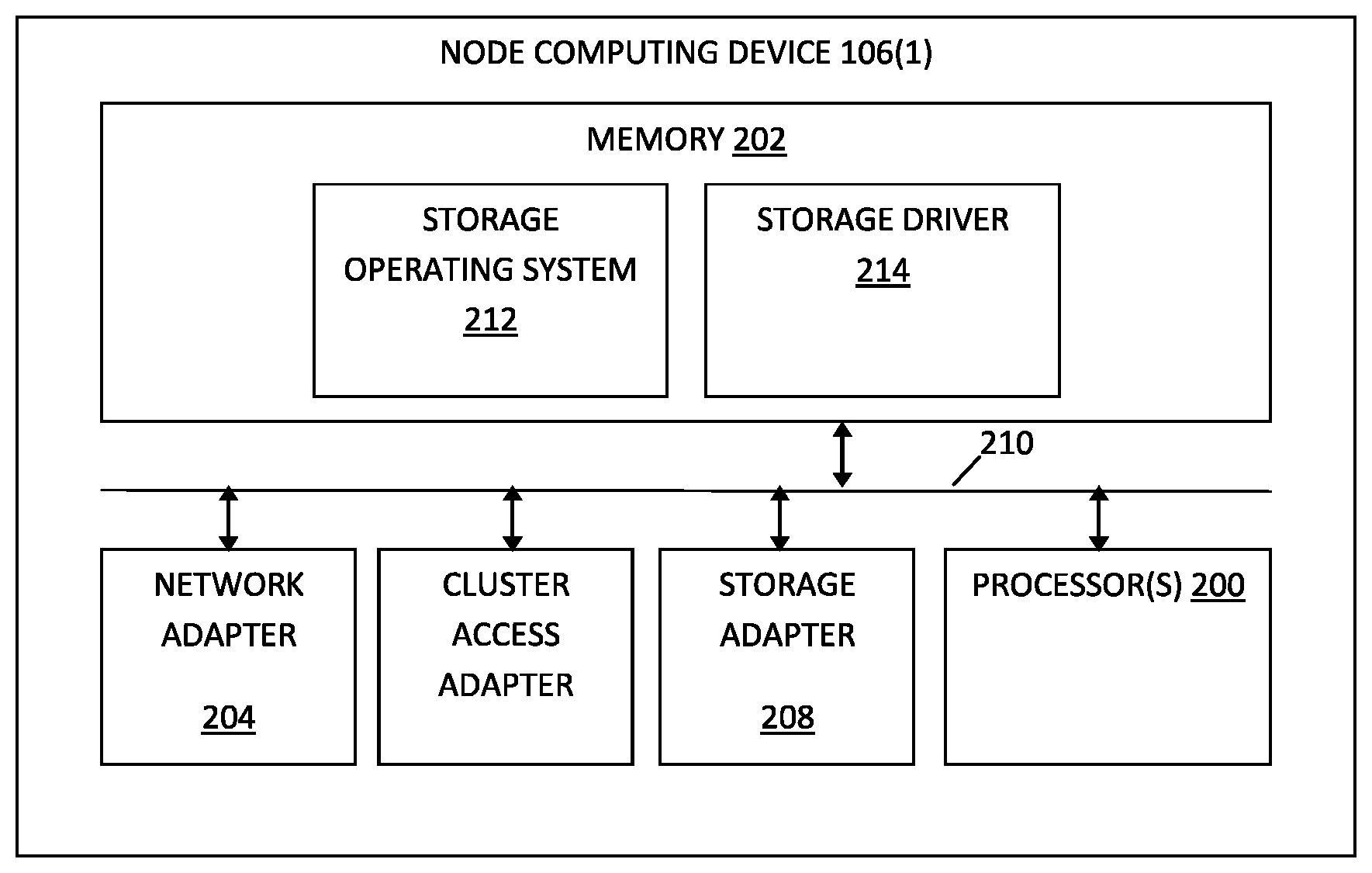
[0006] FIG. 2 is a block diagram of an exemplary one of the node computing devices shown in FIGS. 1; and
[0007] FIG. 3 is a flowchart of an exemplary method for managing workloads in a storage system.
DETAILED DESCRIPTION
[0008] A clustered network environment 100 that may implement one or more aspects of the technology described and illustrated herein is shown in FIG. 1. The clustered network environment 100 includes data storage apparatuses 102(1)-102(n) that are coupled over a cluster fabric 104 facilitating communication between the data storage apparatuses 102(1)-102(n) (and one or more modules, components, etc. therein, such as, node computing devices 106(1)-106(n), for example), although any number of other elements or components can also be included in the clustered network environment 100 in other examples. This technology provides a number of advantages including methods, non-transitory computer readable media, and devices that enable more effectively and efficiently managing workload within a storage system.
[0009] In this example, node computing devices 106(1)-106(n) can be primary or local storage controllers or secondary or remote storage controllers that provide client devices 108(1)-108(n), with access to data stored within data storage devices 110(1)-110(n). The data storage apparatuses 102(1)-102(n) and/or node computing device 106(1)-106(n) of the examples described and illustrated herein are not limited to any particular geographic areas and can be clustered locally and/or remotely. Thus, in one example the data storage apparatuses 102(1)-102(n) and/or node computing device 106(1)-106(n) can be distributed over a plurality of storage systems located in a plurality of geographic locations. In another example, a clustered network can include data storage apparatuses 102(1)-102(n) and/or node computing device 106(1)-106(n) residing in a same geographic location (e.g., in a single onsite rack).
[0010] In the illustrated example, one or more of the client devices 108(1)-108(n), which may be, for example, personal computers (PCs), computing devices or storage (e.g., storage servers), and other computers or peripheral devices, are coupled to the respective data storage apparatuses 102(1)-102(n) by storage network connections 112(1)-112(n). Network connections 112(1)-112(n) may include a local area network (LAN) or wide area network (WAN), for example, that utilizes Network Attached Storage (NAS) protocols, such as a Common Internet File System (CIFS) protocol or a Network File System (NFS) protocol to exchange data packets, a Storage Area Network (SAN) protocol, such as Small Computer System Interface (SCSI) or Fiber Channel Protocol (FCP), an object protocol, such as S3, etc.
[0011] Illustratively, the client devices 108(1)-108(n) may be general-purpose computers running applications, and may interact with the data storage apparatuses 102(1)-102(n) using a client/server model for exchange of information. That is, the client devices 108(1)-108(n) may request data from the data storage apparatuses 102(1)-102(n) (e.g., data on one of the data storage devices 110(1)-110(n) managed by a network storage control configured to process I/O commands issued by the client devices 108(1)-108(n)), and the data storage apparatuses 102(1)-102(n) may return results of the request to the client devices 108(1)-108(n) via the storage network connections 112(1)-112(n).
[0012] The node computing devices 106(1)-106(n) of the data storage apparatuses 102(1)-102(n) can include network or host nodes that are interconnected as a cluster to provide data storage and management services, such as to an enterprise having remote locations, cloud storage (e.g., a storage endpoint may be stored within a data cloud), etc., for example. Such a node computing device 106(1)-106(n) can be a device attached to the fabric 104 as a connection point, redistribution point, or communication endpoint, for example. One or more of the node computing devices 106(1)-106(n) may be capable of sending, receiving, and/or forwarding information over a network communications channel, and could comprise any type of device that meets any or all of these criteria.
[0013] In an example, the node computing device 106(1) may be located on a first storage site and the node computing device 106(n) may be located at a second storage site. The node computing devices 106(1) and 106(n) may be configured according to a disaster recovery configuration whereby a surviving node provides switchover access to the storage devices 110(1)-110(n) in the event a disaster occurs at a disaster storage site (e.g., the node computing device 106(1) provides client device 112(n) with switchover data access to storage devices 110(n) in the event a disaster occurs at the second storage site). In other examples, the node computing device 106(n) can be configured according to an archival configuration and/or the node computing devices 106(1)-106(n) can be configured based on another type of replication arrangement (e.g., to facilitate load sharing). Additionally, while two node computing devices are illustrated in FIG. 1, any number of node computing devices or data storage apparatuses can be included in other examples in other types of configurations or arrangements.
[0014] As illustrated in the clustered network environment 100, node computing devices 106(1)-106(n) can include various functional components that coordinate to provide a distributed storage architecture. For example, the node computing devices 106(1)-106(n) can include network modules 114(1)-114(n) and disk modules 116(1)-116(n). Network modules 114(1)-114(n) can be configured to allow the node computing devices 106(1)-106(n) (e.g., network storage controllers) to connect with client devices 108(1)-108(n) over the storage network connections 112(1)-112(n), for example, allowing the client devices 108(1)-108(n) to access data stored in the clustered network environment 100.
[0015] Further, the network modules 114(1)-114(n) can provide connections with one or more other components through the cluster fabric 104. For example, the network module 114(1) of node computing device 106(1) can access the data storage device 110(n) by sending a request via the cluster fabric 104 through the disk module 116(n) of node computing device 106(n). The cluster fabric 104 can include one or more local and/or wide area computing networks embodied as Infiniband, Fibre Channel (FC), or Ethernet networks, for example, although other types of networks supporting other protocols can also be used.
[0016] Disk modules 116(1)-116(n) can be configured to connect data storage devices 110(1)-110(2), such as disks or arrays of disks, SSDs, flash memory, or some other form of data storage, to the node computing devices 106(1)-106(n). Often, disk modules 116(1)-116(n) communicate with the data storage devices 110(1)-110(n) according to the SAN protocol, such as SCSI, FCP, SAS, NVMe, NVMe-oF for example, although other protocols can also be used. Thus, as seen from an operating system on node computing devices 106(1)-106(n), the data storage devices 110(1)-110(n) can appear as locally attached. In this manner, different node computing devices 106(1)-106(n), etc. may access data blocks through the operating system, rather than expressly requesting abstract files.
[0017] While the clustered network environment 100 illustrates an equal number of network modules 114(1)-114(2) and disk modules 116(1)-116(n), other examples may include a differing number of these modules. For example, there may be a plurality of network and disk modules interconnected in a cluster that do not have a one-to-one correspondence between the network and disk modules. That is, different node computing devices can have a different number of network and disk modules, and the same node computing device can have a different number of network modules than disk modules.
[0018] Further, one or more of the client devices 108(1)-108(n) and server devices 109(1)-109(n) can be networked with the node computing devices 106(1)-106(n) in the cluster, over the storage connections 112(1)-112(n). As an example, respective client devices 108(1)-108(n) that are networked to a cluster may request services (e.g., exchanging of information in the form of data packets) of node computing devices 106(1)-106(n) in the cluster, and the node computing devices 106(1)-106(n) can return results of the requested services to the client devices 108(1)-108(n). In one example, the client devices 108(1)-108(n) can exchange information with the network modules 114(1)-114(n) residing in the node computing devices 106(1)-106(n) (e.g., network hosts) in the data storage apparatuses 102(1)-102(n).
[0019] In one example, the storage apparatuses 102(1)-102(n) host aggregates corresponding to physical local and remote data storage devices, such as local flash or disk storage in the data storage devices 110(1)-110(n), for example. One or more of the data storage devices 110(1)-110(n) can include mass storage devices, such as disks of a disk array. The disks may comprise any type of mass storage devices, including but not limited to magnetic disk drives, flash memory, SSDs, storage class memories and any other similar media adapted to store information, including, for example, data (D) and/or parity (P) information.
[0020] The aggregates include volumes 118(1)-118(n) in this example, although any number of volumes can be included in the aggregates. The volumes 118(1)-118(n) are virtual data stores that define an arrangement of storage and one or more file systems within the clustered network environment 100. Volumes 118(1)-118(n) can span a portion of a disk or other storage device, a collection of disks, or portions of disks, for example, and typically define an overall logical arrangement of file storage. In one example volumes 118(1)-118(n) can include stored data as one or more files or objects that reside in a hierarchical directory structure within the volumes 118(1)-118(n). Volumes 118(1)-118(n) are typically configured in formats that may be associated with particular storage systems, and respective volume formats typically comprise features that provide functionality to the volumes 118(1)-118(n), such as providing an ability for volumes 118(1)-118(n) to form clusters.
[0021] In one example, to facilitate access to data stored on the disks or other structures of the data storage device 110(1)-110(n), a file system (e.g., write anywhere file system) may be implemented that logically organizes the information as a hierarchical structure of directories and files. In this example, respective files may be implemented as a set of disk blocks configured to store information, whereas directories may be implemented as specially formatted files in which information about other files and directories are stored.
[0022] Data can be stored as files or objects within a physical volume and/or a virtual volume, which can be associated with respective volume identifiers, such as file system identifiers (FSIDs). The physical volumes correspond to at least a portion of physical storage devices, such as the data storage device 110(1)-110(n) (e.g., a Redundant Array of Independent (or Inexpensive) Disks (RAID system)) whose address, addressable space, location, etc. does not change. Typically the location of the physical volumes does not change in that the (range of) address(es) used to access it generally remains constant.
[0023] Virtual volumes, in contrast, are stored over an aggregate of disparate portions of different physical storage devices. Virtual volumes may be a collection of different available portions of different physical storage device locations, such as some available space from disks, for example. It will be appreciated that since the virtual volumes are not "tied" to any one particular storage device, virtual volumes can be said to include a layer of abstraction or virtualization, which allows them to be resized and/or flexible in some regards.
[0024] Further, virtual volumes can include one or more logical unit numbers (LUNs), directories, Qtrees, and/or files. Among other things, these features, but more particularly the LUNS, allow the disparate memory locations within which data is stored to be identified, for example, and grouped as a data storage unit. As such, the LUNs may be characterized as constituting a virtual disk or drive upon which data within the virtual volumes is stored within an aggregate. For example, LUNs are often referred to as virtual disks, such that they emulate a hard drive, while they actually comprise data blocks stored in various parts of a volume.
[0025] In one example, the data storage devices 110(1)-110(n) can have one or more physical ports, wherein each physical port can be assigned a target address (e.g., SCSI target address). To represent respective volumes, a target address on the data storage devices 110(1)-110(n) can be used to identify one or more of the LUNs. Thus, for example, when one of the node computing devices 106(1)-106(n) connects to a volume, a connection between the one of the node computing devices 106(1)-106(n) and one or more of the LUNs underlying the volume is created.
[0026] In one example, respective target addresses can identify multiple of the LUNs, such that a target address can represent multiple volumes. The I/O interface, which can be implemented as circuitry and/or software in a storage adapter or as executable code residing in memory and executed by a processor, for example, can connect to volumes by using one or more addresses that identify the one or more of the LUNs.
[0027] Referring to FIG. 2, node computing device 106(1) in this particular example includes processor(s) 200, a memory 202, a network adapter 204, a cluster access adapter 206, and a storage adapter 208 interconnected by a system bus 210. The node computing device 106 also includes a storage operating system 212 installed in the memory 206 that can, for example, implement a Redundant Array of Independent (or Inexpensive) Disks (RAID) data loss protection and recovery scheme to optimize a reconstruction process of data of a failed disk or drive in an array. In some examples, the node computing device 106(n) is substantially the same in structure and/or operation as node computing device 106(1), although the node computing device 106(n) can include a different structure and/or operation in one or more aspects than the node computing device 106(1) in other examples.
[0028] The storage operating system 212 can also manage communications for the node computing device 106(1) among other devices that may be in a clustered network, such as attached to a cluster fabric 104. Thus, the node computing device 106(1) can respond to client device requests to manage data on one of the data storage devices 110(1)-110(n) (e.g., or additional clustered devices) in accordance with the client device requests.
[0029] The storage operating system 212 can also establish one or more file systems including software code and data structures that implement a persistent hierarchical namespace of files and directories, for example. As an example, when a new data storage device (not shown) is added to a clustered network system, the storage operating system 212 is informed where, in an existing directory tree, new files associated with the new data storage device are to be stored. This is often referred to as "mounting" a file system.
[0030] In the example node computing device 106(1), memory 202 can include storage locations that are addressable by the processor(s) 200 and adapters 204, 206, and 208 for storing related software application code and data structures. The processor(s) 200 and adapters 204, 206, and 208 may, for example, include processing elements and/or logic circuitry configured to execute the software code and manipulate the data structures.
[0031] The storage operating system 212, portions of which are typically resident in the memory 202 and executed by the processor(s) 200, invokes storage operations in support of a file service implemented by the node computing device 106(1). Other processing and memory mechanisms, including various computer readable media, may be used for storing and/or executing application instructions pertaining to the techniques described and illustrated herein. For example, the storage operating system 212 can also utilize one or more control files (not shown) to aid in the provisioning of virtual machines.
[0032] Accordingly, the examples may be embodied as one or more non-transitory computer readable media having machine or processor-executable instructions stored thereon for one or more aspects of the present technology, as described and illustrated by way of the examples herein, which when executed by the processor(s) 200, cause the processor(s) 200 to carry out the steps necessary to implement the methods of this technology, as described and illustrated with the examples herein. In some examples, the executable instructions are configured to perform one or more steps of a method, such as one or more of the exemplary methods described and illustrated later with reference to FIG. 3, for example.
[0033] The network adapter 204 in this example includes the mechanical, electrical and signaling circuitry needed to connect the node computing device 106(1) to one or more of the client devices 108(1)-108(n) over storage network connections 112(1)-112(n), which may comprise, among other things, a point-to-point connection or a shared medium, such as a local area network. In some examples, the network adapter 204 further communicates (e.g., using TCP/IP) via the fabric 104 and/or another network (e.g. a WAN) (not shown) with cloud storage devices to process storage operations associated with data stored thereon.
[0034] The storage adapter 208 cooperates with the storage operating system 212 executing on the node computing device 106(1) to access information requested by one of the client devices 108(1)-108(n) (e.g., to access data on a data storage device 110(1)-110(n) managed by a network storage controller). The information may be stored on any type of attached array of writeable media such as magnetic disk drives, SSDs, and/or any other similar media adapted to store information.
[0035] In the exemplary data storage devices 110(1)-110(n), information can be stored in data blocks on disks. The storage adapter 208 can include input/output (I/O) interface circuitry that couples to the disks over an I/O interconnect arrangement, such as a storage area network (SAN) protocol (e.g., Small Computer System Interface (SCSI), iSCSI, hyperSCSI, Fiber Channel Protocol (FCP)). The information is retrieved by the storage adapter 208 and, if necessary, processed by the processor(s) 200 (or the storage adapter 208 itself) prior to being forwarded over the system bus 210 to the network adapter 204 (and/or the cluster access adapter 206 if sending to another node computing device in the cluster) where the information is formatted into a data packet and returned to a requesting one of the client devices 108(1)-108(2) and/or sent to another node computing device attached via the cluster fabric 104. In some examples, a storage driver 214 in the memory 202 interfaces with the storage adapter to facilitate interactions with the data storage devices 110(1)-110(n), as described and illustrated in more detail later with reference to FIG. 3.
[0036] Referring to FIG. 3, an exemplary method for managing workload within a storage system will now be described. In step 305 in this example, the node computing device 106(1) generates a quality of service proposal for all the other node computing devices 106(n) within a policy group, although the node computing device 106(1) can prepare the quality of service proposal to other subsets of the nodes or to other devices. In this example, the quality of service proposal is a cluster transaction proposal intended for all the node computing devices 106(2)-106(n) within the policy group and the proposal includes a request for one or more of the quality of service parameters, such as a current rate limit, a required rate limit, and/or a cluster rate limit, although the proposal can include other types or amounts of information.
[0037] In step 310, the node computing device 106(1) broadcasts the generated quality of service proposal to all the other node computing devices 106(2)-106(n) within the policy group, although the node computing device 106(2)-106(n) can broadcast the quality of service proposal to other devices within the storage cluster.
[0038] In step 315, the node computing device 106(1) receives a response from all the other node computing devices 106(2)-106(n) within the policy group, although in other examples a smaller subset of the responses may be received or utilized. In this example, the received response includes the requested current rate limit, the required rate limit, and/or the cluster rate limit, although the received response can include other types or amounts of information.
[0039] Next in step 320, the node computing device 106(1) identifies the bandwidth requirements from all of the received responses. In this example, the node computing device 106(1) gets a holistic picture of the bandwidth requirements for all the node computing devices 106(2)-106(n) within the policy group. Using the identified bandwidth requirements, in this example the node computing device 106(1) can get data associated with the amount of network traffic processed by each of the node computing devices and can also get data associated with an amount of spare bandwidth any of the node computing devices 106(2)-106(n) have.
[0040] In step 325, the node computing device 106(1) determines a rate balancing policy for all node computing devices 106(2)-106(n) within the policy group which may comprise all or different subsets of the node computing devices 106(2)-106(n). By way of example, one rate balancing policy can include distributing bandwidth of the cluster storage limit equally across all node computing devices 106(2)-106(n) within the policy group when one of the node computing devices requires bandwidth and no spare bandwidth is available. Additionally, another example of the rate balancing policy can include dividing the total spare limit among all node computing devices within the policy group that require the bandwidth when there is spare bandwidth available within the policy group. Further in this example, a one second settling time may be used on the node computing device 106(1) when the workload of the all the node computing devices 106(2)-106(n) within the policy group is constantly changing, although other types and amounts of settling time can be used. Furthermore, when one of the node computing devices 106(2)-106(n) within the policy group does not have the entire cluster bandwidth limit assigned and has need of additional bandwidth, it may generate grace tokens equivalent to 50 milliseconds of bandwidth to aid the client traffic while a new rate balance proposal is raised. Using the aforementioned rate balancing policy, the disclosed technology can perform rate balancing where traffic can flow through any node computing devices 106(1)-106(n) within the storage cluster. Additionally, a fast shifting rate limit is a determined with a scale out container that spans across node computing devices 106(1)-16(n) in the storage cluster.
[0041] In step 330, the node computing device 106(1) generates a revised quality of service parameter proposal including an absolute effective bandwidth limit for each of the node computing device 106(2)-106(n) within the policy group, although the revised quality of service proposal can include other types or amounts of information. In this example, the absolute effective bandwidth is determined based on the type of the rate balancing policy that is selected in step 325, although the absolute effective bandwidth can be determined based on other types or numbers of other parameters.
[0042] In step 335, the node computing device 106(1) broadcasts the revised quality of service proposal to all of the node computing devices 106(2)-106(n) within the policy group, although the node computing device 106(1) can broadcast the revised quality of service proposal to other devices within the storage cluster.
[0043] In step 340, the node computing device 106(1) receives a response from all the node computing devices 106(2)-106(n) within the policy group to the revised quality of service proposal. In this example, this received response includes accepting the revised quality of service proposal, although the node computing device 106(1) can receive other types of responses from the node computing devices 106(2)-106(n) within the policy group.
[0044] In step 345, the node computing device 106(1) and all the other node computing devices 106(2)-106(n) adjust the local bandwidth configurations based on the absolute effective bandwidth limit that was received in the revised quality of service proposal, although the node computing device 106(1) and/or the other node computing devices 106(2)-106(n) can adjust the local bandwidth configurations based on other types or numbers of parameters and may adjust in other manners. The exemplary method ends at step 350.
[0045] Having thus described the basic concept of the technology, it will be rather apparent to those skilled in the art that the foregoing detailed disclosure is intended to be presented by way of example only, and is not limiting. Various alterations, improvements, and modifications will occur and are intended to those skilled in the art, though not expressly stated herein. These alterations, improvements, and modifications are intended to be suggested hereby, and are within the spirit and scope of the technology. Additionally, the recited order of processing elements or sequences, or the use of numbers, letters, or other designations therefore, is not intended to limit the claimed processes to any order except as may be specified in the claims. Accordingly, the technology is limited only by the following claims and equivalents thereto.
* * * * *
D00000
D00001
D00002
D00003
XML
uspto.report is an independent third-party trademark research tool that is not affiliated, endorsed, or sponsored by the United States Patent and Trademark Office (USPTO) or any other governmental organization. The information provided by uspto.report is based on publicly available data at the time of writing and is intended for informational purposes only.
While we strive to provide accurate and up-to-date information, we do not guarantee the accuracy, completeness, reliability, or suitability of the information displayed on this site. The use of this site is at your own risk. Any reliance you place on such information is therefore strictly at your own risk.
All official trademark data, including owner information, should be verified by visiting the official USPTO website at www.uspto.gov. This site is not intended to replace professional legal advice and should not be used as a substitute for consulting with a legal professional who is knowledgeable about trademark law.