Perimeter Pocket System
Brinkman; Mark E. ; et al.
U.S. patent application number 16/548647 was filed with the patent office on 2020-02-27 for perimeter pocket system. This patent application is currently assigned to Fry Reglet Corporation. The applicant listed for this patent is Fry Reglet Corporation. Invention is credited to Mark E. Brinkman, Robert Stuart.
| Application Number | 20200063447 16/548647 |
| Document ID | / |
| Family ID | 69584443 |
| Filed Date | 2020-02-27 |


View All Diagrams
| United States Patent Application | 20200063447 |
| Kind Code | A1 |
| Brinkman; Mark E. ; et al. | February 27, 2020 |
PERIMETER POCKET SYSTEM
Abstract
A system for forming perimeter pockets includes a number of flat members and a number of different extruded shapes. The extruded shapes are configured for joining selected ones of the flat members into perimeter pockets adapted for different applications.
| Inventors: | Brinkman; Mark E.; (Cumming, GA) ; Stuart; Robert; (Rome, GA) | ||||||||||
| Applicant: |
|
||||||||||
|---|---|---|---|---|---|---|---|---|---|---|---|
| Assignee: | Fry Reglet Corporation Santa Fe Springs CA |
||||||||||
| Family ID: | 69584443 | ||||||||||
| Appl. No.: | 16/548647 | ||||||||||
| Filed: | August 22, 2019 |
Related U.S. Patent Documents
| Application Number | Filing Date | Patent Number | ||
|---|---|---|---|---|
| 62722031 | Aug 23, 2018 | |||
| Current U.S. Class: | 1/1 |
| Current CPC Class: | E04B 9/30 20130101; E04F 19/06 20130101 |
| International Class: | E04F 19/06 20060101 E04F019/06; E04B 9/30 20060101 E04B009/30 |
Claims
1. A system for forming perimeter pockets, the system comprising: a number of flat members; and a number of different extruded shapes configured for joining selected ones of the flat members into perimeter pockets adapted for different applications.
2. The system of claim 1, wherein the number of flat members comprises different flat members, including solid and perforated flat members.
3. The system of claim 1, wherein the number of different extruded shapes comprise one or more extruded shapes defining slots of a shape and size to receive edges of one or more of the number of flat members.
4. The system of claim 3, wherein the slots are of a shape and size to receive edges of the one or more flat members in a press fit.
5. The system of claim 3, wherein the slots define bulbous ends for receiving adhesive.
6. The system of claim 1, wherein at least some of the slots include serrated features for engaging the received flat members.
7. The system of claim 1, wherein the number of different extruded shapes comprise an extruded shape defining slots of a shape and size to receive edges of two flat members with the two flat members at right angles to each other.
8. The system of claim 1, wherein the number of different extruded shapes comprise an extruded shape defining slots of a shape and size to receive edges of two flat members with the two flat members parallel with each other.
9. The system of claim 8, wherein the extruded shape defining slots of a shape and size to receive edges of two flat members with the two flat members parallel with each other also includes a hook feature.
10. The system of claim 1, wherein the number of different extruded shapes comprise an extruded shape defining slots of a shape and size to receive edges of two flat members with the two flat members at right angles to each other, the extruded shape also including an extending leg opposite one of the two flat members.
11. The system of claim 10, wherein the extruded shape defining slots of a shape and size to receive edges of two flat members with the two flat members at right angles to each other and including an extending leg opposite one of the two flat members also defines an attached tray.
12. The system of claim 1, wherein the number of different extruded shapes comprise an extruded shape defining a slot of a shape and size to receive an edge of one of the flat members, the extruded shape also including an extending leg at a right angle to the received flat member.
13. The system of claim 12, wherein the extruded shape defining a slot of a shape and size to receive an edge of one of the flat members and including an extending leg at a right angle to the received flat member also comprises a hook feature opposite the extending leg.
14. The system of claim 12, wherein the extruded shape defining a slot of a shape and size to receive an edge of one of the flat members and including an extending leg at a right angle to the received flat member also comprises hook features on a face of a web of the extruded shape.
15. The system of claim 12, wherein the extruded shape defining a slot of a shape and size to receive an edge of one of the flat members and including an extending leg at a right angle to the received flat member also comprises a corner bead.
16. The system of claim 1, further comprising at least one member having a brake-formable shape.
17. The system of claim 1, wherein the number of different extruded shapes comprise an extruded shape defining a slot of a shape and size to receive an edge of one of the flat members at a first edge of the extruded shape, having a right-angle leg at a second edge of the extruded shape, and having at least two hook features on a first face of a web of the extruded shape between the first and second edges.
18. The system of claim 17, wherein the extruded shape defining a slot of a shape and size to receive an edge of one of the flat members at a first edge of the extruded shape, having a right-angle leg at a second edge of the extruded shape, and having at least two hook features on a face of a web of the extruded shape between the first and second edges, also comprises at least two additional hook features on a second face of the web opposite the first face.
19. The system of claim 1, wherein the number of different extruded shapes included in the system comprise three or more shapes selected from the group of shapes consisting of: an extruded shape defining slots of a shape and size to receive edges of two flat members with the two flat members at right angles to each other; an extruded shape defining slots of a shape and size to receive edges of two flat members with the two flat members parallel with each other; an extruded shape defining slots of a shape and size to receive edges of two flat members with the two flat members parallel with each other, the extruded shape also including a hook feature; an extruded shape defining slots of a shape and size to receive edges of two flat members with the two flat members at right angles to each other, and includes an extending leg opposite one of the two flat members; an extruded shape defining slots of a shape and size to receive edges of two flat members with the two flat members at right angles to each other, the extruded shape also including an extending leg opposite one of the two flat members, and the extruded shape also defining an attached tray; an extruded shape defining a slot of a shape and size to receive an edge of one of the flat members, and including an extending leg at a right angle to the received flat member; an extruded shape defining a slot of a shape and size to receive an edge of one of the flat members, and including an extending leg at a right angle to the received flat member, and also including a hook feature opposite the extending leg; an extruded shape defining a slot of a shape and size to receive an edge of one of the flat members, and including an extending leg at a right angle to the received flat member, and also including hook features on a face of a web of the extruded shape; an extruded shape defining a slot of a shape and size to receive an edge of one of the flat members, and including an extending leg at a right angle to the received flat member, and also including a corner bead; an extruded shape defining a slot of a shape and size to receive an edge of one of the flat members at a first edge of the extruded shape, having a right-angle leg at a second edge of the extruded shape, and having at least two hook features on a first face of a web of the extruded shape between the first and second edges; and an extruded shape defining a slot of a shape and size to receive an edge of one of the flat members at a first edge of the extruded shape, having a right-angle leg at a second edge of the extruded shape, and having at least two hook features on a first face of a web of the extruded shape between the first and second edges, and also comprising at least two additional hook features on a second face of the web opposite the first face.
20. A perimeter pocket, comprising: an extruded shape defining slots disposed at right angles to each other; and first and second flat, elongate panels, wherein edges of the first and second flat panels are disposed respectively in slots of the extruded shape such that the flat panels are held at right angles to each other and define a rectangular space.
21. The perimeter pocket of claim 20, wherein the edges of the first and second flat panels are press-fitted into the slots, or are secured in the slots by an adhesive.
Description
CROSS REFERENCE TO RELATED APPLICATIONS
[0001] This application claims priority to U.S. Provisional Patent Application No. 62/722,031, filed Aug. 23, 2018 and titled "Perimeter Pocket System", the entire disclosure of which is hereby incorporated by reference herein for all purposes.
BACKGROUND OF THE INVENTION
[0002] A ceiling pocket or perimeter pocket is an enclosed space often provided above or adjacent to a suspended ceiling, for routing electrical wires, enclosing shades, or the like. Various structures have been provided for constructing such pockets, and the structures themselves are also sometimes called perimeter pockets.
[0003] Previous perimeter pockets have lacked adaptability to different situations
BRIEF SUMMARY OF THE INVENTION
[0004] The terms "invention," "the invention," "this invention" and "the present invention" used in this patent are intended to refer broadly to all of the subject matter of this patent and the patent claims below. Statements containing these terms should not be understood to limit the subject matter described herein or to limit the meaning or scope of the patent claims below. Embodiments of the invention covered by this patent are defined by the claims below, not this summary. This summary is a high-level overview of various aspects of the invention and introduces some of the concepts that are further described in the Detailed Description section below. This summary is not intended to identify key or essential features of the claimed subject matter, nor is it intended to be used in isolation to determine the scope of the claimed subject matter. The subject matter should be understood by reference to the entire specification of this patent, all drawings, and each claim.
[0005] According to one aspect, a system for forming perimeter pockets comprises a number of flat members and a number of different extruded shapes configured for joining selected ones of the flat members into perimeter pockets adapted for different applications. In some embodiments, the number of flat members comprises different flat members, including solid and perforated flat members. In some embodiments, the number of different extruded shapes comprise one or more extruded shapes defining slots of a shape and size to receive edges of one or more of the number of flat members. In some embodiments, the slots are of a shape and size to receive edges of the one or more flat members in a press fit. In some embodiments, the slots define bulbous ends for receiving adhesive. In some embodiments, at least some of the slots include serrated features for engaging the received flat members. In some embodiments, the number of different extruded shapes comprise an extruded shape defining slots of a shape and size to receive edges of two flat members with the two flat members at right angles to each other. In some embodiments, the number of different extruded shapes comprise an extruded shape defining slots of a shape and size to receive edges of two flat members with the two flat members parallel with each other. In some embodiments, the extruded shape defining slots of a shape and size to receive edges of two flat members with the two flat members parallel with each other also includes a hook feature. In some embodiments, the number of different extruded shapes comprise an extruded shape defining slots of a shape and size to receive edges of two flat members with the two flat members at right angles to each other, the extruded shape also including an extending leg opposite one of the two flat members. In some embodiments, the extruded shape defining slots of a shape and size to receive edges of two flat members with the two flat members at right angles to each other and including an extending leg opposite one of the two flat members also defines an attached tray. In some embodiments, the number of different extruded shapes comprise an extruded shape defining a slot of a shape and size to receive an edge of one of the flat members, the extruded shape also including an extending leg at a right angle to the received flat member. In some embodiments, the extruded shape defining a slot of a shape and size to receive an edge of one of the flat members and including an extending leg at a right angle to the received flat member also comprises a hook feature opposite the extending leg. In some embodiments, the extruded shape defining a slot of a shape and size to receive an edge of one of the flat members and including an extending leg at a right angle to the received flat member also comprises hook features on a face of a web of the extruded shape. In some embodiments, the extruded shape defining a slot of a shape and size to receive an edge of one of the flat members and including an extending leg at a right angle to the received flat member also comprises a corner bead. In some embodiments, the system further comprises at least one member having a brake-formable shape. In some embodiments, the number of different extruded shapes comprise an extruded shape defining a slot of a shape and size to receive an edge of one of the flat members at a first edge of the extruded shape, having a right-angle leg at a second edge of the extruded shape, and having at least two hook features on a first face of a web of the extruded shape between the first and second edges. In some embodiments, the extruded shape defining a slot of a shape and size to receive an edge of one of the flat members at a first edge of the extruded shape, having a right-angle leg at a second edge of the extruded shape, and having at least two hook features on a face of a web of the extruded shape between the first and second edges, also comprises at least two additional hook features on a second face of the web opposite the first face. In some embodiments, the number of different extruded shapes comprise three or more shapes selected from the group of shapes consisting of: an extruded shape defining slots of a shape and size to receive edges of two flat members with the two flat members at right angles to each other; an extruded shape defining slots of a shape and size to receive edges of two flat members with the two flat members parallel with each other; an extruded shape defining slots of a shape and size to receive edges of two flat members with the two flat members parallel with each other, the extruded shape also including a hook feature; an extruded shape defining slots of a shape and size to receive edges of two flat members with the two flat members at right angles to each other, and includes an extending leg opposite one of the two flat members; an extruded shape defining slots of a shape and size to receive edges of two flat members with the two flat members at right angles to each other, the extruded shape also including an extending leg opposite one of the two flat members, and the extruded shape also defining an attached tray; an extruded shape defining a slot of a shape and size to receive an edge of one of the flat members, and including an extending leg at a right angle to the received flat member; an extruded shape defining a slot of a shape and size to receive an edge of one of the flat members, and including an extending leg at a right angle to the received flat member, and also including a hook feature opposite the extending leg; an extruded shape defining a slot of a shape and size to receive an edge of one of the flat members, and including an extending leg at a right angle to the received flat member, and also including hook features on a face of a web of the extruded shape; an extruded shape defining a slot of a shape and size to receive an edge of one of the flat members, and including an extending leg at a right angle to the received flat member, and also including a corner bead; an extruded shape defining a slot of a shape and size to receive an edge of one of the flat members at a first edge of the extruded shape, having a right-angle leg at a second edge of the extruded shape, and having at least two hook features on a first face of a web of the extruded shape between the first and second edges; and an extruded shape defining a slot of a shape and size to receive an edge of one of the flat members at a first edge of the extruded shape, having a right-angle leg at a second edge of the extruded shape, and having at least two hook features on a first face of a web of the extruded shape between the first and second edges, and also comprising at least two additional hook features on a second face of the web opposite the first face.
[0006] According to another aspect, a perimeter pocket comprises an extruded shape defining slots disposed at right angles to each other, and first and second flat, elongate panels. Edges of the first and second flat panels are disposed respectively in slots of the extruded shape such that the flat panels are held at right angles to each other and define a rectangular space. In some embodiments, the edges of the first and second flat panels are press-fitted into the slots, or are secured in the slots by an adhesive.
BRIEF DESCRIPTION OF THE DRAWINGS
[0007] FIG. 1 shows an upper oblique view of a perimeter pocket in accordance with an embodiment of the invention.
[0008] FIG. 2 shows an exploded view of the perimeter pocket of FIG. 1.
[0009] FIG. 3 illustrates a close-up orthogonal view of the connection of top and side flat pieces in the perimeter pocket of FIG. 1.
[0010] FIG. 4 is an exploded view of the connection of FIG. 3.
[0011] FIG. 5 shows a self-tapping screw poised to join pieces in the perimeter pocket of FIG. 1.
[0012] FIG. 6 shows the screw of FIG. 5 after installation.
[0013] FIG. 7 is a close-up orthogonal view of part of the perimeter pocket of FIG. 1.
[0014] FIG. 8 is a close-up orthogonal view of the connection of top and side flat pieces by an extruded shape, in the perimeter pocket of FIG. 1.
[0015] FIGS. 9 and 10 illustrate a perimeter pocket in accordance with other embodiments of the invention.
[0016] FIGS. 11-13 illustrate a perimeter pocket in accordance with other embodiments of the invention.
[0017] FIGS. 14 and 15 illustrate a perimeter pocket in accordance with other embodiments of the invention.
[0018] FIGS. 16 and 17 illustrate a perimeter pocket in accordance with other embodiments of the invention.
[0019] FIGS. 18 and 19 illustrate a perimeter pocket in accordance with embodiments of the invention.
[0020] FIG. 20 illustrates a perimeter pocket in accordance with embodiments of the invention.
[0021] FIG. 21 illustrates a perimeter pocket in accordance with embodiments of the invention.
[0022] FIG. 22 illustrates a perimeter pocket in accordance with embodiments of the invention.
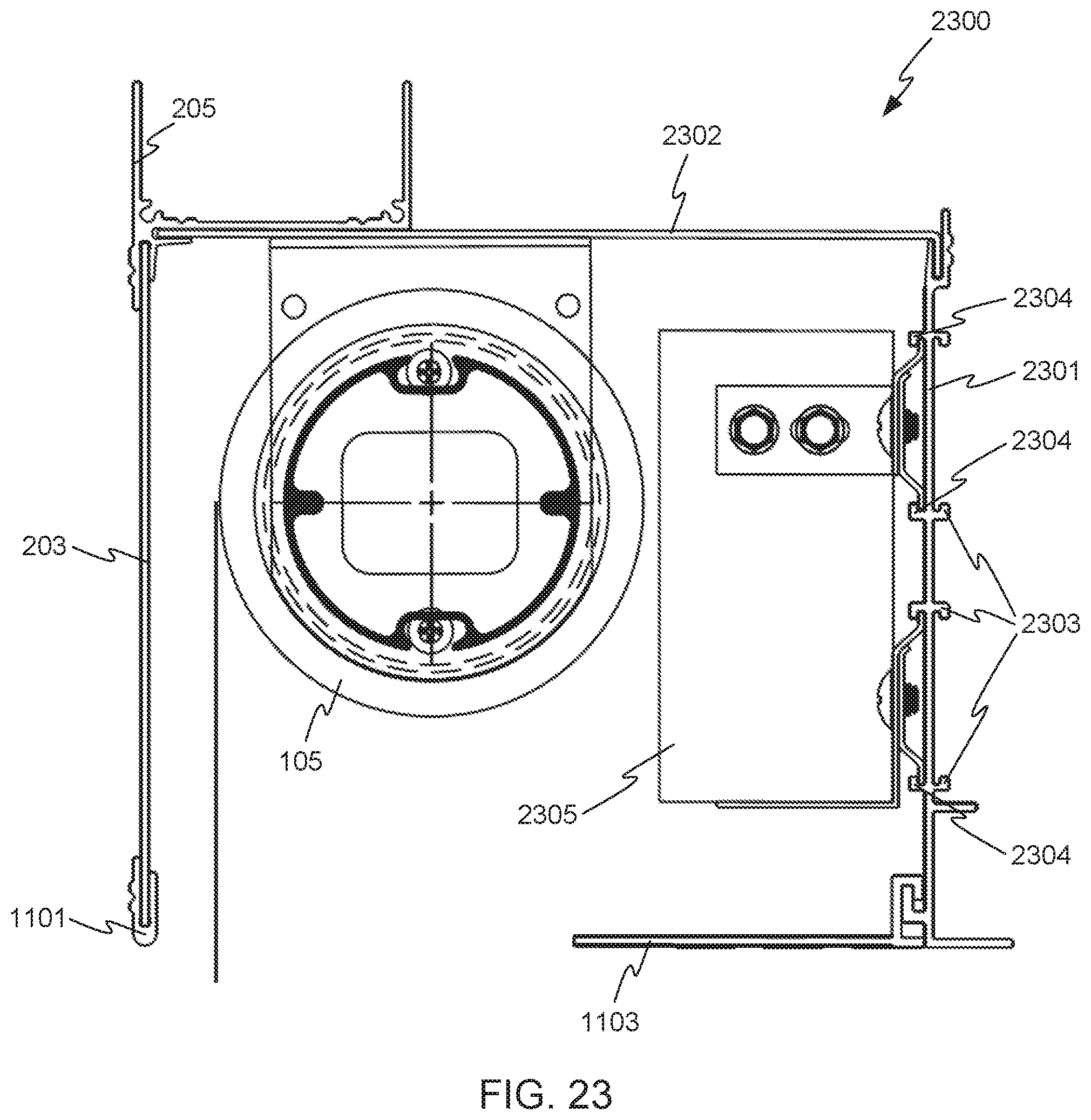
[0023] FIG. 23 illustrates a perimeter pocket in accordance with other embodiments of the invention.
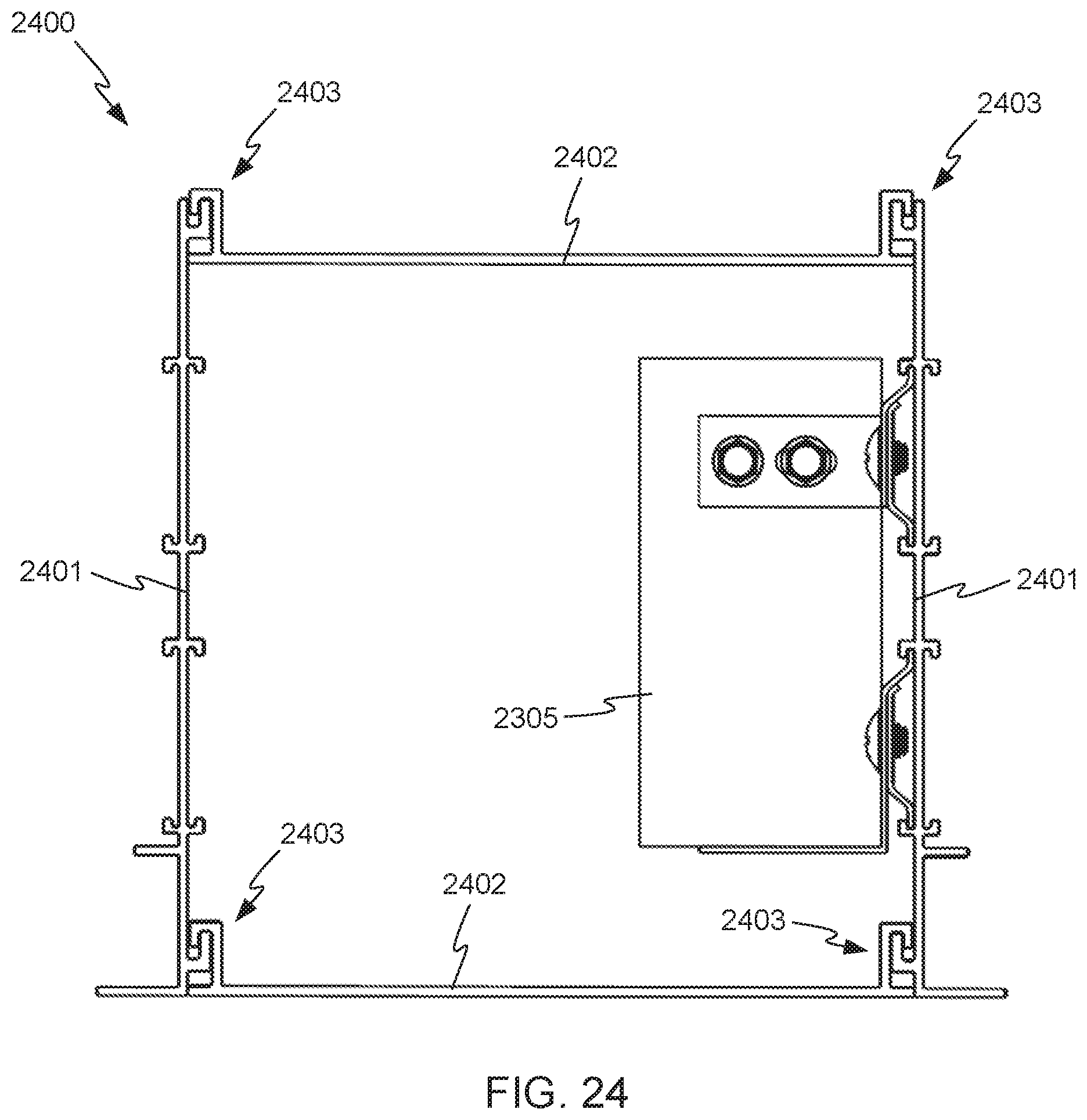
[0024] FIG. 24 illustrates a perimeter pocket in accordance with other embodiments of the invention.
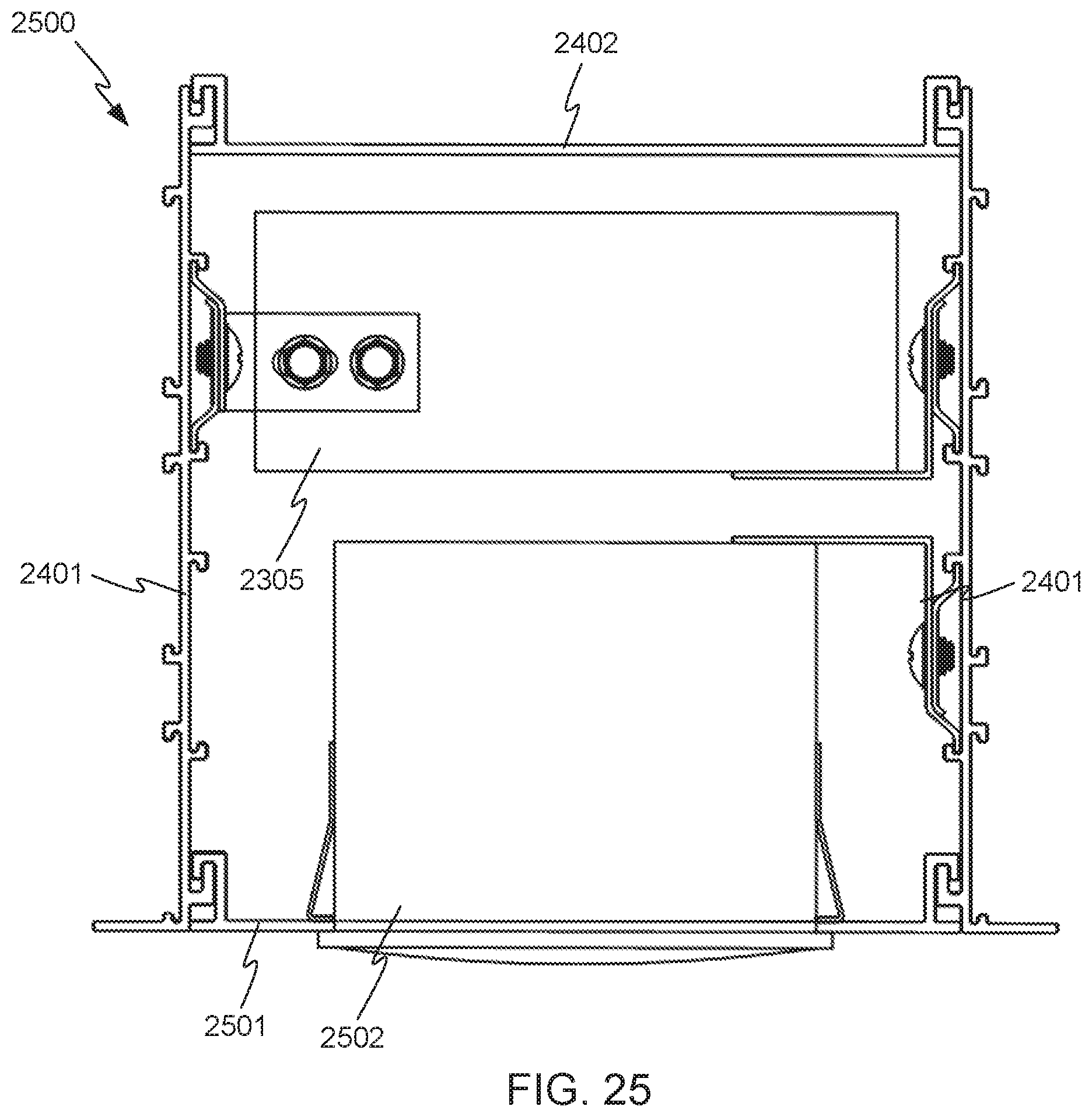
[0025] FIG. 25 illustrates a perimeter pocket in accordance with other embodiments of the invention.
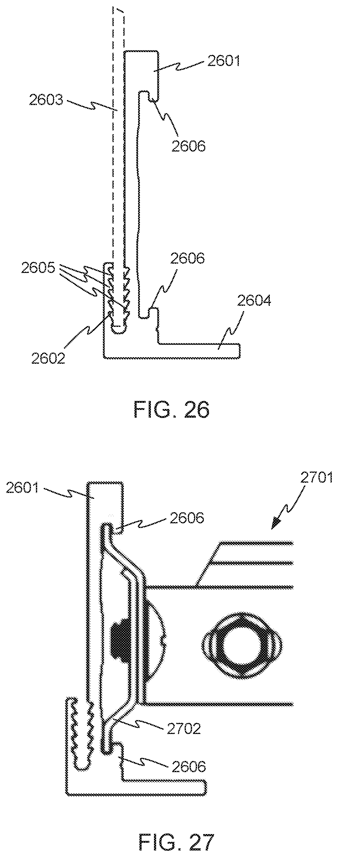
[0026] FIG. 26 illustrates an end view of an extruded shape in accordance with other embodiments, of the invention.
[0027] FIG. 27 shows the extruded shape of FIG. 26 with a suspended ceiling structure attached.
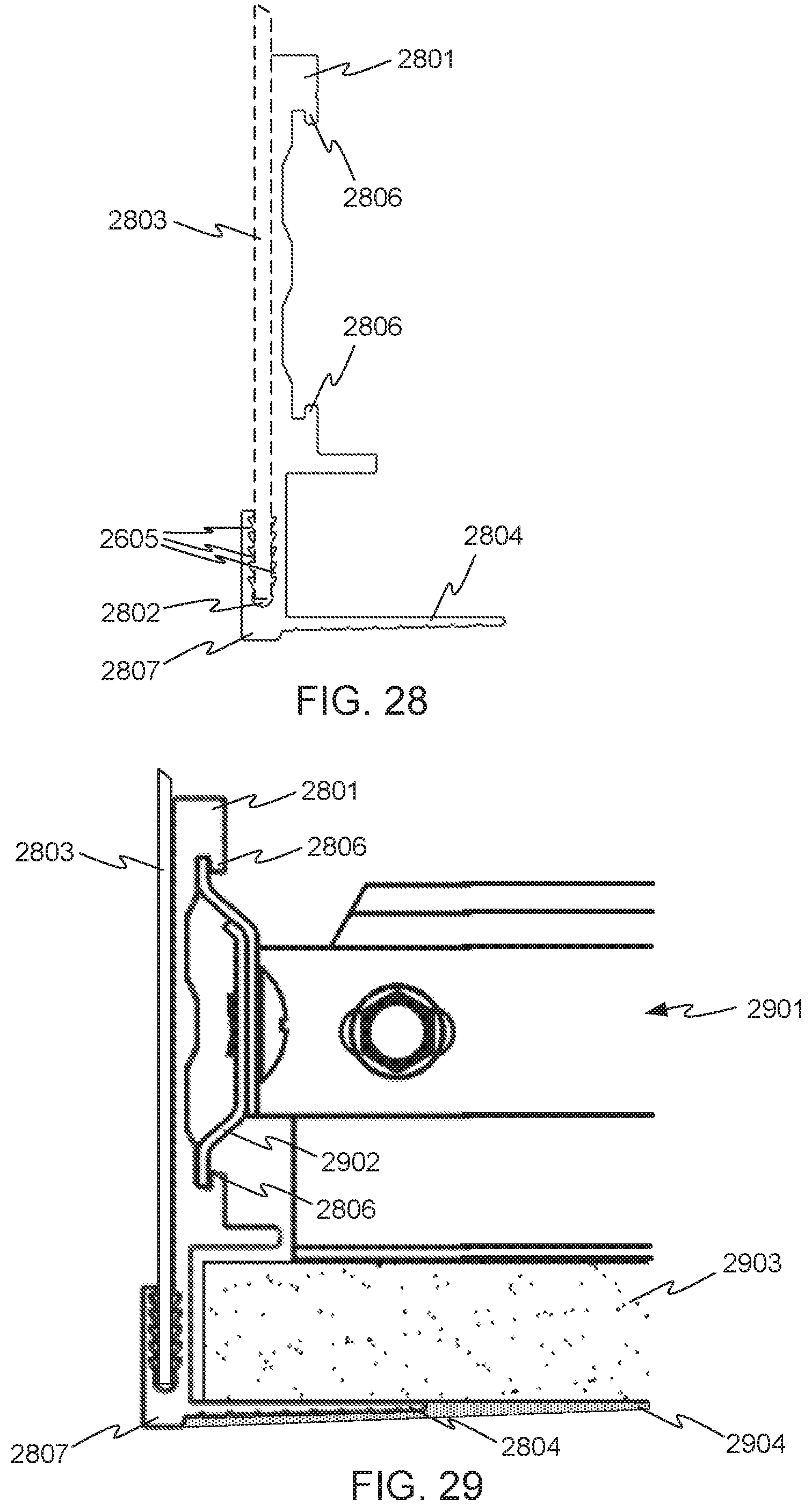
[0028] FIG. 28 illustrates an end view of another extruded shape in accordance with other embodiments of the invention.
[0029] FIG. 29 shows the extruded shape of FIG. 28, with additional elements attached, in accordance with embodiments of the invention.
[0030] FIG. 30 illustrates an end view of another extruded shape in accordance with other embodiments of the invention.
[0031] FIG. 31 illustrates an end view of another extruded shape in accordance with other embodiments of the invention.
DETAILED DESCRIPTION OF THE INVENTION
[0032] The subject matter of embodiments of the present invention is described here with specificity to meet statutory requirements, but this description is not necessarily intended to limit the scope of the claims. The claimed subject matter may be embodied in other ways, may include different elements or steps, and may be used in conjunction with other existing or future technologies. This description should not be interpreted as implying any particular order or arrangement among or between various steps or elements except when the order of individual steps or arrangement of elements is explicitly described.
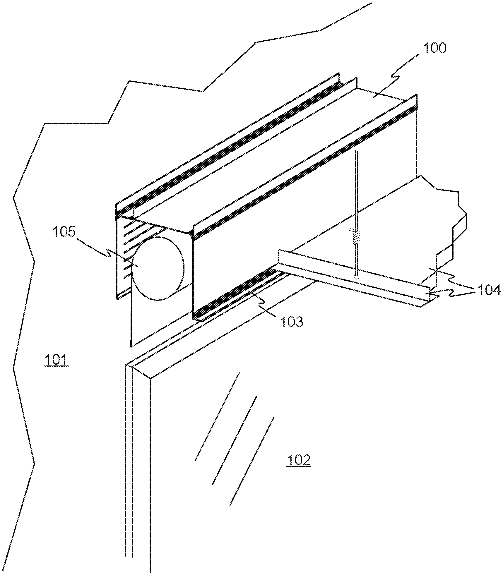
[0033] FIG. 1 shows an upper oblique view of a perimeter pocket 100 in accordance with an embodiment of the invention. The perimeter pocket 100 is generally rectangular and elongate, and is mounted to a wall 101, for example the outer wall of a building, and above a window 102. The perimeter pocket 100 includes a ledge 103 that supports one edge of a suspended ceiling 104. The example perimeter pocket 100 houses a roller shade 105 configured to be raised and lowered in front of the window 102. In other embodiments, a perimeter pocket in accordance with the invention may be used to provide housing for other applications such as lighting, wiring, air supply and return, sprinklers, or other options.
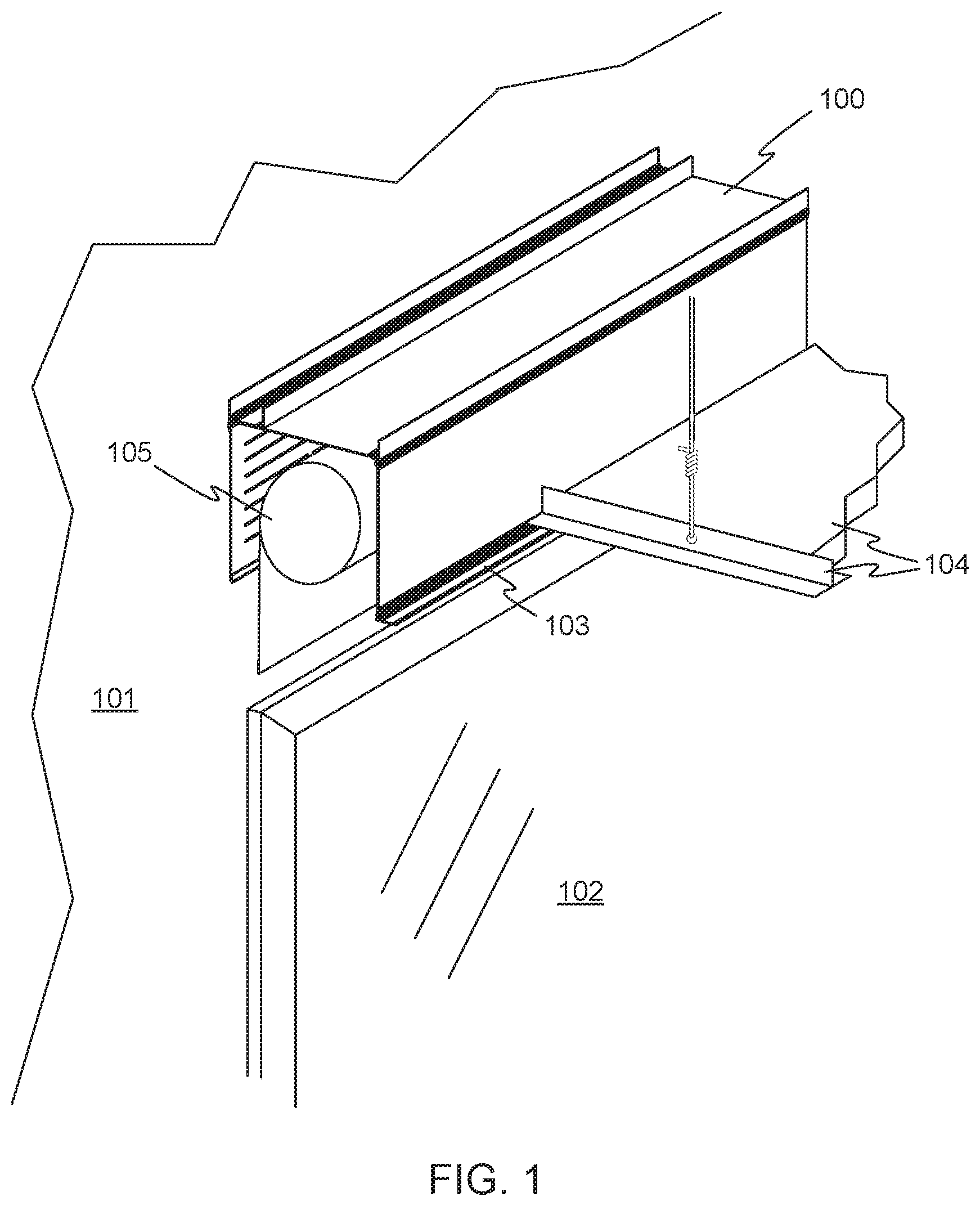
[0034] FIG. 2 shows an exploded view of the perimeter pocket 100. In accordance with embodiments of the invention, a system of combinable parts can be selected and combined in various ways, to make perimeter pockets suitable for a wide variety of situations. In the example of FIG. 2, the perimeter pocket 100 includes flat top and side pieces 201 and 202, and a perforated flat side piece 203. The flat pieces 201, 202, and 203 may be stamped from sheet metal, for example sheet steel or aluminum. In other embodiments, such pieces may be made of molded or extruded polymer, or cut from polymer sheet stock, or made by any other suitable process from any suitable material.
[0035] The flat pieces of the perimeter pocket 100 are joined together using extruded corner shapes 204 and 205, and a ledge for suspended ceiling 104 is provided by an edge shape 206. Edge shape 206 is an example of an extruded shape having a slot of a shape and size to receive an edge of a flat member, and including an extending leg at a right angle to the received flat member. These and other combinable components are described in more detail below.
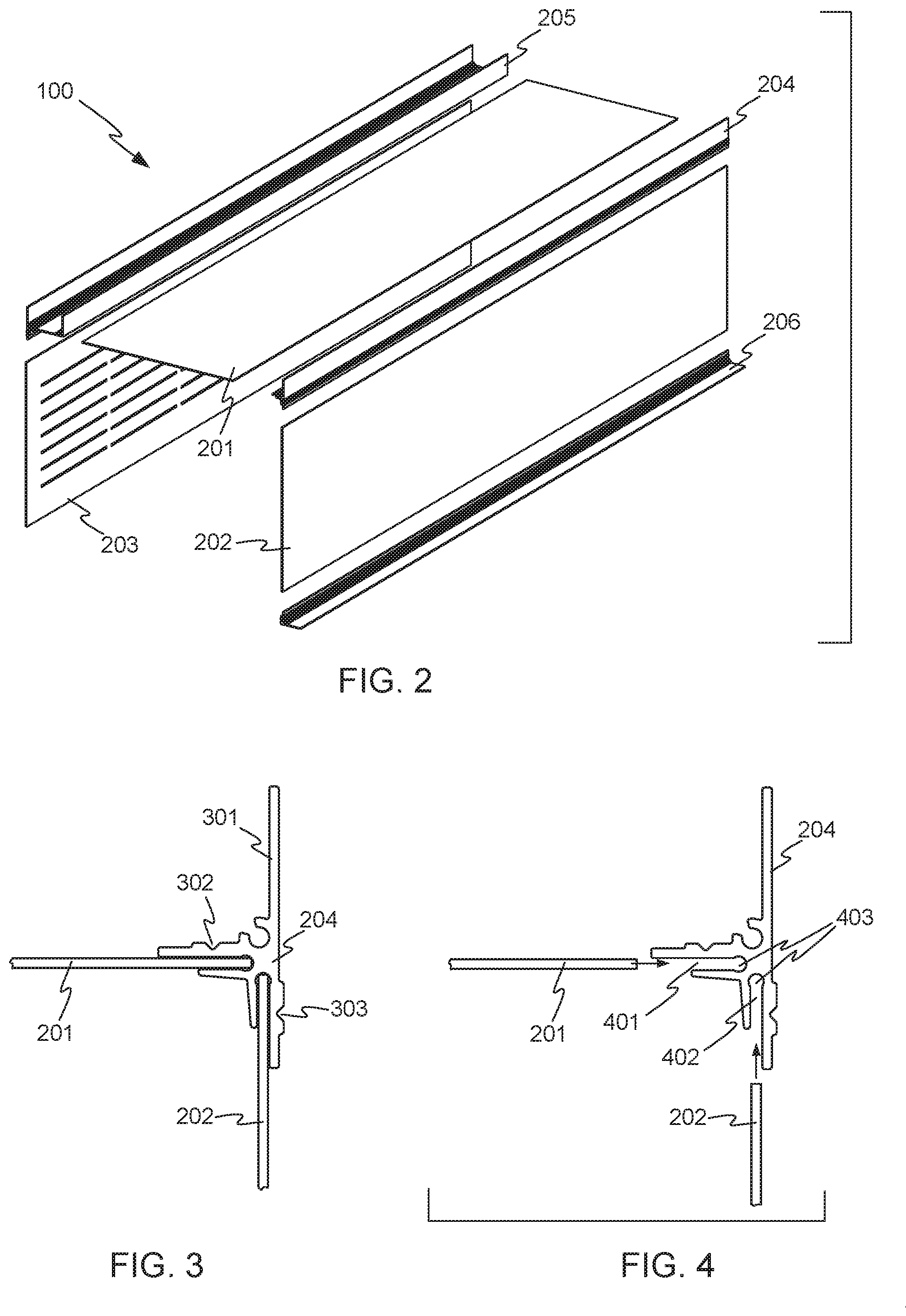
[0036] FIG. 3 illustrates a close-up orthogonal view of the connection of the top and side flat pieces 201 and 202 by the extruded shape 204, and FIG. 4 illustrates an exploded view of the connection of FIG. 3. The corner shape 204 defines two slots 401 and 402, disposed at right angles and sized and shaped to receive respective edges of the flat pieces 201 and 202. The corner shape 204 may be an extruded shape made from aluminum, a polymer, or another suitable material. The flat pieces 201 and 202 may be joined to the corner shape 204, for example using an epoxy adhesive (not shown) in the slots 401 and 402. Bulbous ends 403 may be formed in the throats of the slots 401 and 402, for receiving the adhesive and accommodating any excess adhesive. In other embodiments, the flat pieces 201 and 202 may be press-fit into the slots 401 and 402. In other embodiments, side pieces and extruded shapes may snap together, or may be joined by other techniques. When the various parts of a perimeter pocket are made of a polymer material, they may be joined by solvent bonding or other bonding techniques.
[0037] In some embodiments, slots such as the slots 401 and 402 in extruded shape 204 (and other shapes described herein) may be formed with serrated features, to further secure flat pieces in the slots. Extruded shapes having slots with serrated features are described in more detail below.
[0038] An upper leg 301 of the corner shape 204 may extend above the flat piece 201, opposite the flat piece 202, and may, in conjunction with corner shape 205, provide a tray for containing wiring or other items laid on the top of the perimeter pocket 100, or may act as a supporting member when attached via hanger wire to structure above.
[0039] Grooves 302 and 303 may be provided on the legs of the corner shape 204, for conveniently receiving self-tapping screws for joining the flat pieces 201 and 202 to the corner shape 204, if desired. FIG. 5 shows a self-tapping screw 501 poised to join the flat piece 202 and the corner shape 204, and FIG. 6 shows the connection with the self-tapping screw 501 installed. The groove shape may help prevent at least some wandering of the screw 501 as it penetrates the corner shape 204. Screws such as the screw 501 may be used alone or in addition to an epoxy or other adhesive, for example to hold parts in proper position while the adhesive dries. In other embodiments, a pop rivet or other kind of fasteners or an adhesive may be used in place of the screw 501 so as not to interfere with the interior of the pocket.
[0040] FIG. 7 is a close-up orthogonal view of the bottom of side flat piece 202 and extruded shape 206, illustrating how the perimeter pocket may be designed to interface with abutting ceiling construction. The side flat piece 202 may be attached to the extruded shape 206 in a manner similar to the attachment of the side flat piece 202 to the upper extruded shape 204 as described above. For example, the side flat piece 202 may be inserted into slot 701 in the extruded shape 206, and affixed with an adhesive if desired. Alternatively or in addition, a screw (not shown) may be used to connect the side flat piece 202 to the extruded shape 206, preferably at groove 702.
[0041] The extruded shape 206 may be especially helpful in joining a suspended ceiling such as the suspended ceiling 104 to the perimeter pocket 100. For example, the extruded shape 206 includes a lower shelf 703, on which structure 704 of the suspended ceiling 104 may rest. The extruded shape 206 is also an example of an extruded shape defining a slot of a shape and size to receive an edge of one of the flat members, the extruded shape also including an extending leg at a right angle to the received flat member.
[0042] Although not shown in FIG. 7, and extruded shape such as the extruded shape 206 may also be provided with hook features for further securing the suspended ceiling 104 structure to the perimeter pocket. An additional extruded shape similar to the extruded shape 206 and having hook features is described in more detail below,
[0043] FIG. 8 is a close-up orthogonal view of the connection of the top and side flat pieces 201 and 203 by the extruded shape 205. The connections of the flat pieces 201 and 203 to the extruded shape 205 may be similar to those described above, in which the flat pieces 201 and 203 are inserted into slots 801, in the extruded shape 205. An adhesive may be used, and screws may be inserted with the aid of grooves 802 if desired. The extruded shape 205 includes two protrusions 803 that define a space 804 between them, and that may act as supporting members when attached via hanger wire to the structure above. The space 804 may be conveniently used as a wire chase or for supporting or containing other items. The extruded shape 205 is an example of a shape defining slots of a shape and size to receive edges of two flat members with the two flat members at right angles to each other and including an extending leg opposite one of the two flat members, and also defining an attached tray.
[0044] For the purposes of this disclosure, an "extruded shape" is an elongate member having a constant cross section suitable for initial formation by extrusion. Some such shapes may also be formable by molding, casting, or bending of flat stock. This use of the word "shape" is common in the metal fabrication, plastic fabrication, and building trades. Additional features such as through holes, threads, or other features may be added after the initial formation of the extruded shape, and the member is still considered to be an extruded shape.
[0045] A variety of other extruded shapes may be provided, and are combinable with flat pieces to create a large number of perimeter pocket configurations useful in different situations. The various extruded shapes may be made of aluminum, a polymer, or another suitable material. The additional extruded shapes may include features similar to some of those discussed above, for example slots for receiving flat pieces and grooves for facilitating the insertion of self-tapping screws. Other features and configurations will be described below. However, it is to be understood that the above and following examples are not intended to be an exhaustive catalog of the possible configurations.
[0046] FIGS. 9 and 10 illustrate a perimeter pocket 900 in accordance with other embodiments of the invention. The perimeter pocket 900 uses some of the same parts as the perimeter pocket 100 discussed above, for example a top flat piece 201 and a side flat piece 202, joined at a right angle. In addition, corner extruded shape 206a is the same as the extruded shape 206 of FIG. 2, and may partially support a suspended ceiling 104. However, at the wall side of the perimeter pocket 900, an extruded shape 206b is used, identical to the extruded shape 206a. The upturned side 901 of the extruded shape 201b may facilitate connecting the perimeter pocket 900 to a wall. In addition, the top and side flat pieces 201 and 202 are joined using a corner extruded shape 902, which lacks any flange or leg similar to leg 301 of the extruded shape 204. The perimeter pocket 900 is shown housing the roller shade 105, but this is only an example use.
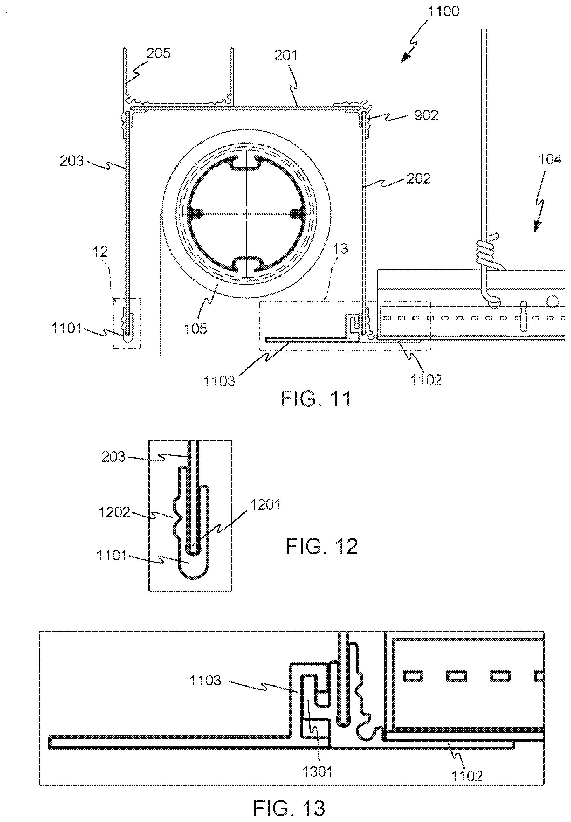
[0047] FIGS. 11-13 illustrate a perimeter pocket 1100 in accordance with other embodiments of the invention. The perimeter pocket 1100 shares some features with the perimeter pockets 100 and 900 discussed above, for example the flat pieces 201, 202, and 203, and the extruded shapes 205 and 902. However, the lower end of the flat piece 203 is capped off with a different extruded shape 1101, which has a slot 1201 for receiving the flat piece 203, and a groove 1202 for receiving a screw if desired. In addition, the extruded shape 1102 includes a slot of a shape and size to receive a flat piece and an extending leg, but differs from the extruded shape 206 described above in that the extruded shape 1102 includes a hook feature 1301 onto which an optional hanging floor member 1103 can be mounted, to partially close off the perimeter pocket 1100 from below.
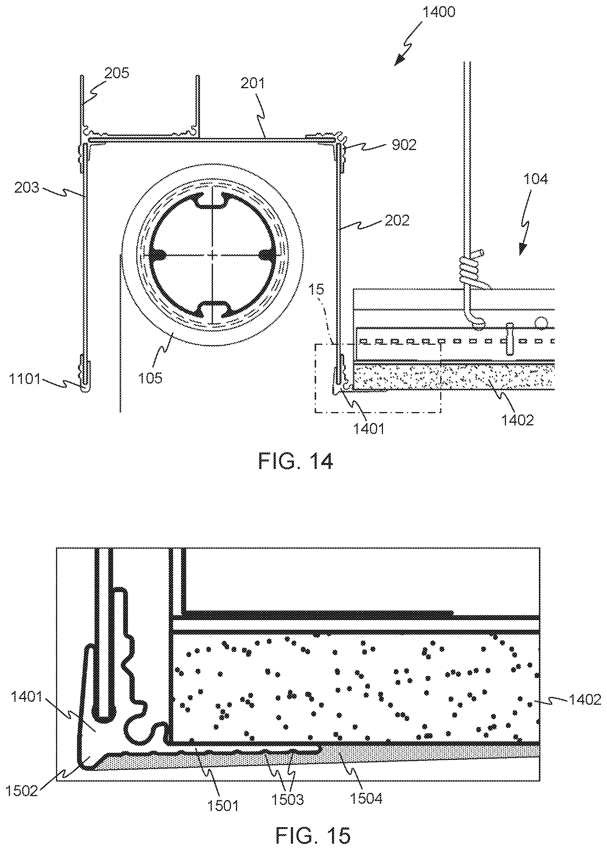
[0048] FIGS. 14 and 15 illustrate a perimeter pocket 1400 in accordance with other embodiments of the invention. The perimeter pocket 1400 shares some features with the perimeter pockets 100, 900, and 1100 discussed above, for example the flat pieces 201, 202, and 203, and the extruded shapes 205, 902, and 1101. However, the lower edge of the flat piece 202 is joined to a different extruded shape 1401. The extruded shape 1401 is similar to the extruded shape 206 discussed above, and forms a shelf 1501 for supporting a suspended ceiling 104, but additionally includes a corner bead 1502 along its corner edge, and indentations 1503 in its shelf 1501 that may especially configure the extruded shape 1401 for use in a ceiling that is finished with drywall board 1402. As is shown in FIG. 15, drywall compound 1504 (also known as "mud") may be placed to cover the extruded shape 1401 and the edge of the drywall board 1402, for a finished look. Drywall tape (not shown) may be placed over the transition between the shelf 1501 and the drywall board 1402 before placing the drywall compound 1504. The bead 1502 provides a boundary for the drywall compound 1504, and also provides a hard edge for a drywall knife to ride against as the drywall compound 1504 is placed.
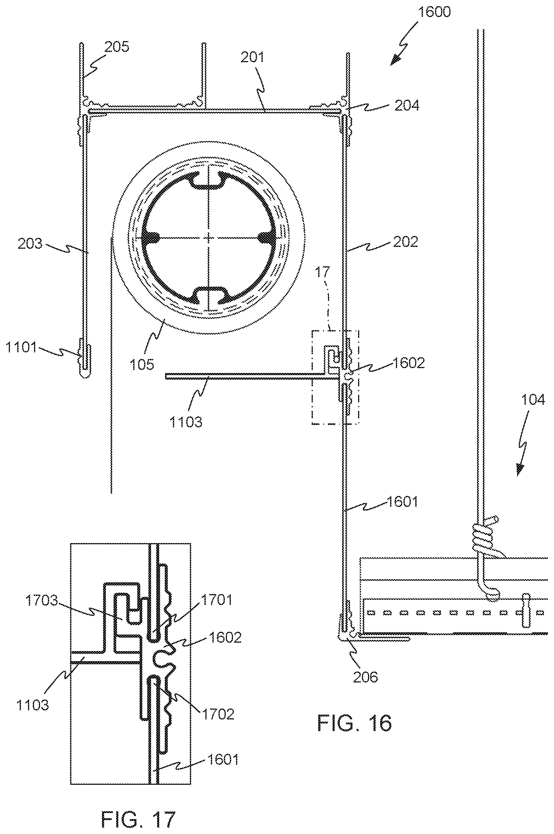
[0049] FIGS. 16 and 17 illustrate a perimeter pocket 1600 in accordance with other embodiments of the invention. The perimeter pocket 1600 shares some features with the perimeter pockets 100, 900, 1100, and 1400 discussed above, for example the flat pieces 201, 202, and 203, and the extruded shapes 204, 205, 206, and 1101, and the floor member 1103. However, the perimeter pocket 1600 further includes an additional lower flat piece 1601, joined to the flat piece 202 by another kind of extruded shape 1602. The extruded shape 1602 includes aligned slots 1701 and 1702, so that two flat members can be joined edge-to-edge in a parallel, and in this case, coplanar arrangement. In the example of FIGS. 16 and 17, this capability is used to create a double height perimeter pocket, further hiding the roller shade 105. The extruded shape 1602 may also include a hook feature 1703 for supporting the floor member 1103.
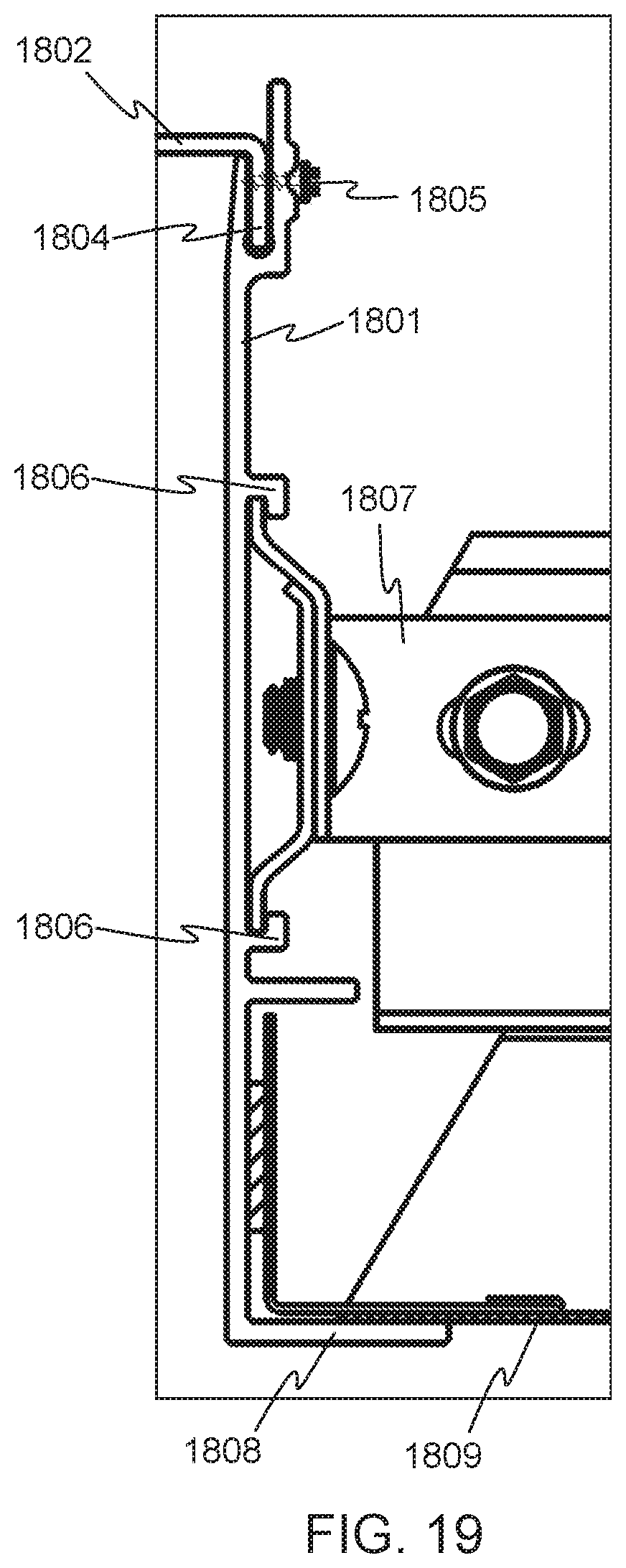
[0050] FIGS. 18 and 19 illustrate a perimeter pocket 1800 in accordance with embodiments of the invention. It will be recognized that the perimeter pocket 1800 need not be at the perimeter of a room, but may be installed in any location. (The same is true of at least some of the other perimeter pockets described above.) In the perimeter pocket 1800, two extruded side shapes 1801 are placed "back-to-back" at the sides of the perimeter pocket 1800. A brake-formable top piece 1802 spans the space 1803 defined by the extruded side shapes 1801. For the purposes of this disclosure, a "brake-formable" piece is one of a shape amenable to formation by bending of sheet stock as may be accomplished using a press brake. In some cases, for example the top piece 1801, the shape may also be amendable to formation by casting, molding, extrusion, or other processes. The sizes of the various pieces of the perimeter pocket 1800 may vary, but in some embodiments, the side pieces 1801 are about 4 inches tall, and the top piece 1802 is about 5 inches wide, so that the cross sectional area of the perimeter pocket 1800 is about 4.times.5 inches. Each of the side pieces 1801 may have a slot for receiving the folded-down edges 1804 of the top piece 1802. The top piece 1802 may be attached to the side pieces 1801 in any suitable way, but in the embodiment shown, it is attached using screws 1805, which are placed in grooves, as described above.
[0051] Each of the side pieces 1801 includes hooks 1806 for receiving clips 1807, for mounting of the suspended ceiling 104. The side pieces 1801 also include shelves 1808 for supporting other kinds of decorative ceiling treatments 1809. The side piece 1801 is also an example of an extruded shape defining a slot of a shape and size to receive an edge of one of the flat members at a first edge of the extruded shape, having a right-angle leg at a second edge of the extruded shape, and having at least two hook features on a first face of a web of the extruded shape between the first and second edges.
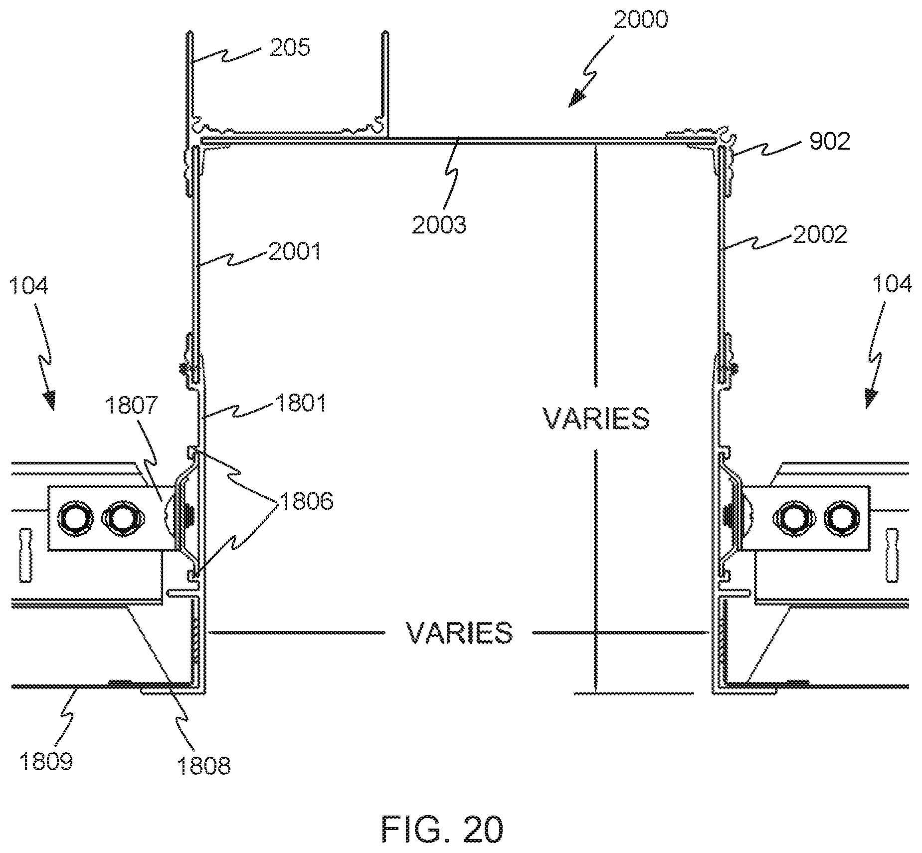
[0052] FIG. 20 illustrates a perimeter pocket 2000 in accordance with embodiments of the invention. The perimeter pocket 2000 is similar to the perimeter pocket 1800 described above, in that it uses extruded side pieces 1801. However, rather than a brake-formed top piece, the perimeter pocket 2000 includes additional flat side pieces 2001 and 2002 inserted into the slots at the tops of the extruded side pieces 1801. An additional flat piece 2003 spans the top of the perimeter pocket 2000, and is joined to the flat side pieces 2001 and 2002 using extruded corner shapes such as the shapes 205 and 902 as shown. Any of the other suitable shapes described herein could be used as well. As compared with the perimeter pocket 1800, the perimeter pocket 2000 is taller, and may accommodate additional or larger items.
[0053] FIG. 21 illustrates a perimeter pocket 2100 in accordance with embodiments of the invention. The perimeter pocket 2100 is similar to the perimeter pocket 1800 described above, but uses different extruded side pieces 2101. The side pieces 2101 have similar slots at their top ends for receiving a brake-formed top piece 2102, to define a space 2103. The ends 2104 of the top piece 2102 are inserted into the slots, and may be attached using screws or another method. The side pieces 2101 differ from the side pieces 1801 described above at least in that the hooks 2105 are positioned differently, enabling a suspended ceiling 104 to rest directly on the shelves 2106.
[0054] FIG. 22 illustrates a perimeter pocket 2200 in accordance with embodiments of the invention. The perimeter pocket 2200 is similar to the perimeter pocket 2100 described above, in that it uses the extruded side pieces 2101. However, the height of the perimeter pocket 2100 is extended as compared with the perimeter pocket 2100, by inserting flat side pieces 2201 and 2202 into the slots at the tops of the side pieces 2101, and joining them to a flat top piece 2203 using appropriate extruded corner shapes, in this case the shapes 902.
[0055] FIG. 23 illustrates a perimeter pocket 2300 in accordance with other embodiments of the invention. The perimeter pocket 2300 is similar in some ways to the perimeter pocket 1100 described above, in that it includes a flat side piece 203, an extruded shape 1101 at the bottom of the flat side piece 203, a corner formed by extruded shape 205, and a floor member 1103. However, the other side of the perimeter pocket 2300 is formed by an extruded shape 2301, and the top of the perimeter pocket 2300 is formed by a brake-formed piece 2302. The extruded side shape 2301 includes a number of hook features 2303 on its outer surface, some of which may be similar to the hook features 1806 of extruded shape 1801 described above. In addition, the extruded side shape 2301 includes hook feature 2304 on its inside surface as well. The inside hook features 2304 may be useful for mounting other kinds of items inside the perimeter pocket 2300, for example batteries for operating the roller shade 105, an electrical transformer for lighting, or other kinds of items, indicated generically as item 2305 in FIG. 23.
[0056] FIG. 24 illustrates a perimeter pocket 2400 in accordance with other embodiments of the invention. The perimeter pocket 2400 includes extruded side pieces 2401. In addition, both the top and bottom of the perimeter pocket 2400 are formed as an extruded piece 2402 that couples to the side pieces 2401 via hook features 2403, rather than being inserted into slots in extruded corner pieces. Unlike the perimeter pockets described above, the perimeter pocket 2400 is completely enclosed, so any items such as item 2305 inside the perimeter pocket 2400 are not exposed.
[0057] FIG. 25 illustrates a perimeter pocket 2500 in accordance with other embodiments of the invention. The perimeter pocket 2400 is similar to the perimeter pocket 2400, including the use of extruded side pieces 2401 and top piece 2402. However, bottom piece 2501 includes an opening for a light 2502. The bottom piece 2501 may be initially made by extrusion, and the opening for the light 2502 cut into the extruded piece in a secondary machining process.
[0058] FIG. 26 illustrates an end view of an extruded shape 2601 in accordance with other embodiments, of the invention. The extruded shape 2601 is similar to the extruded shape 206 described above, in that it includes a slot 2602 for receiving a flat member 2603 (shown in dashed lines), and also has an extending leg 2604 at a right angle to the received flat member 2603.
[0059] In addition, the slot 2602 is formed with serrated features 2605. The serrated features may be spaced to interfere slightly with the flat member 2603 as the flat member 2603 is inserted into the slot 2602. The serrated shape of the serrated features 2605 may enhance the grip of the slot 2602 on the flat member 2603, to help prevent accidental disassembly of a perimeter pocket including the extruded shape 2601 and the flat member 2603. In other embodiments, the serrated features may provide reservoirs for adhesive placed in the slot 2602.
[0060] The extruded shape 2601 also includes hook features 2606, similar to the hook features 1806 described above, for attaching the structure of a suspended ceiling. FIG. 27 shows the extruded shape 2601 with a suspended ceiling structure 2701 attached via a clip 2702 engaged with the hook features 2606.
[0061] FIG. 28 illustrates an end view of another extruded shape 2801 in accordance with other embodiments of the invention. The extruded shape 2801 is similar to the extruded shape 2601 described above, in that it includes a slot 2802 for receiving a flat member 2803 (shown in dashed lines), and also has an extending leg 2804 at a right angle to the received flat member 2803. The slot 2802 has serrated features 2805, and the extruded shape 2801 includes hook features 2806 similar to the hook features 2606 described above.
[0062] The extruded shape 2801 also includes a corner bead 2807, similar to the corner bead 1502 described above. Extruded shapes 2601 and 2801 are examples of an extruded shape defining a slot of a shape and size to receive an edge of one of the flat members, and including an extending leg at a right angle to the received flat member, and also including hook features on a face of a web of the extruded shape.
[0063] FIG. 29 illustrates the extruded shape 2801, with additional elements attached, in accordance with embodiments of the invention. A ceiling structure 2901 is attached to the extruded shape 2801 via a clip 2902, which engages the hook features 2806. The ceiling structure also includes drywall board 2903. Drywall compound 2904 (also known as "mud") may be placed to cover the extruded shape 2801 and the edge of the drywall board 2903, for a finished look. Drywall tape (not shown) may be placed over the transition between the extending leg 2804 and the drywall board 2903 before placing the drywall compound 2904. The bead 2807 provides a boundary for the drywall compound 2904, and also provides a hard edge for a drywall knife to ride against as the drywall compound 2904 is placed.
[0064] FIG. 30 illustrates an end view of another extruded shape 3001 in accordance with other embodiments of the invention. The extruded shape 3001 is similar to the extruded shape 205 described above, in that it includes slots 3002 and 3003 for receiving flat members 3004 and 3005 (shown in dashed lines), and also includes two protrusions 3006 that define a space 3007 between them. However, the slots 3002 and 3003 of the extruded shape 3001 also include serrated features 3008, similar to the serrated features 2605 described above.
[0065] FIG. 31 illustrates an end view of another extruded shape 3101 in accordance with other embodiments of the invention. The extruded shape 3101 is similar to the extruded shape 1101 described above, but includes serrated features 3102, similar to the serrated features 2605 and 3008 described above.
[0066] Other kinds of items may be placed in a perimeter pocket, in accordance with embodiments of the invention. For example, such perimeter pockets may serve as a mounting places or housings for security cameras, smoke or gas detectors, sprinkler system components such as sprinkler heads, or other kinds of items.
[0067] The various parts of perimeter pockets embodying the invention may be finished in any suitable way, for example by painting, powder coating, plating, or another process or combination of processes.
[0068] It will be apparent to those skilled in the art that various modifications and variations can be made in the method and system of the present invention without departing from the spirit or scope of the invention. Thus, it is intended that the present invention include modifications and variations that are within the scope of the appended claims and their equivalents. It is to be understood that any workable combination of the features and capabilities disclosed herein is also considered to be disclosed.
* * * * *
D00000
D00001
D00002
D00003
D00004
D00005
D00006
D00007
D00008
D00009
D00010
D00011
D00012

D00013
D00014
D00015
D00016
D00017
D00018

XML
uspto.report is an independent third-party trademark research tool that is not affiliated, endorsed, or sponsored by the United States Patent and Trademark Office (USPTO) or any other governmental organization. The information provided by uspto.report is based on publicly available data at the time of writing and is intended for informational purposes only.
While we strive to provide accurate and up-to-date information, we do not guarantee the accuracy, completeness, reliability, or suitability of the information displayed on this site. The use of this site is at your own risk. Any reliance you place on such information is therefore strictly at your own risk.
All official trademark data, including owner information, should be verified by visiting the official USPTO website at www.uspto.gov. This site is not intended to replace professional legal advice and should not be used as a substitute for consulting with a legal professional who is knowledgeable about trademark law.