Pyrolysis Gasification System
JEON; CHI JUNG ; et al.
U.S. patent application number 16/202806 was filed with the patent office on 2020-02-27 for pyrolysis gasification system. The applicant listed for this patent is CHI JUNG JEON, Kentec Enviro Solutions LLC., SUNG CHUN KIM, JUN IL SONG. Invention is credited to CHI JUNG JEON, SUNG CHUN KIM, JUN IL SONG.
| Application Number | 20200063050 16/202806 |
| Document ID | / |
| Family ID | 69587135 |
| Filed Date | 2020-02-27 |
| United States Patent Application | 20200063050 |
| Kind Code | A1 |
| JEON; CHI JUNG ; et al. | February 27, 2020 |
PYROLYSIS GASIFICATION SYSTEM
Abstract
Provided is a pyrolysis gasification system including a hopper, a loading chamber, a gas generating furnace, an ash discharge unit, and an oxygen supply unit, wherein the loading chamber is provided at an upper end thereof with a first sealing gate to seal the loading chamber, and the gas generating furnace is provided at an upper portion thereof with a second sealing gate to seal the gas generating furnace, such that when the raw material is fed into the gas generating furnace, external air is prevented from entering the gas generating furnace and combustion gas in the gas generating furnace is prevented from being discharged to an outside, whereby oxygen is supplied into the gas generating furnace to increase the content and concentration of carbon monoxide and hydrogen in combustion gas generated during pyrolysis, and thus it is possible to increase the production of syngas.
| Inventors: | JEON; CHI JUNG; (Bucheon-si, KR) ; KIM; SUNG CHUN; (Seongnam-si, KR) ; SONG; JUN IL; (Seongnam-si, KR) | ||||||||||
| Applicant: |
|
||||||||||
|---|---|---|---|---|---|---|---|---|---|---|---|
| Family ID: | 69587135 | ||||||||||
| Appl. No.: | 16/202806 | ||||||||||
| Filed: | November 28, 2018 |
| Current U.S. Class: | 1/1 |
| Current CPC Class: | C10J 2300/1628 20130101; C10J 2300/0959 20130101; C10J 2200/09 20130101; C10J 3/36 20130101; C10J 2200/36 20130101; C10J 3/007 20130101; C10J 3/34 20130101; C10J 3/30 20130101; C10J 3/82 20130101; C10J 2200/156 20130101; C10J 2200/152 20130101 |
| International Class: | C10J 3/00 20060101 C10J003/00; C10J 3/34 20060101 C10J003/34; C10J 3/82 20060101 C10J003/82 |
Foreign Application Data
| Date | Code | Application Number |
|---|---|---|
| Aug 23, 2018 | KR | 10-2018-0098565 |
Claims
1. A pyrolysis gasification system comprising: a hopper configured such that raw material is fed thereinto; a loading chamber configured such that the raw material fed into the hopper is temporarily stored therein; a gas generating furnace configured such that the raw material stored in the loading chamber is fed thereinto, and pyrolyzed and incinerated; an ash discharge unit configured to discharge ash completely pyrolyzed in the gas generating furnace; and an oxygen supply unit configured to supply oxygen into the gas generating furnace, wherein the loading chamber is provided at an upper end thereof with a first sealing gate to seal the loading chamber, and the gas generating furnace is provided at an upper portion thereof with a second sealing gate to seal the gas generating furnace, such that when the raw material is fed into the gas generating furnace, external air is prevented from entering the gas generating furnace and combustion gas in the gas generating furnace is prevented from being discharged to an outside.
2. The system of claim 1, wherein the first sealing gate includes: a first door rotatably provided on a first side of the upper end of the loading chamber by a first hinge rod; and a second door rotatably provided on a second side of the upper end of the loading chamber by a second hinge rod, and disposed to face the first door, wherein the first hinge rod and the second hinge rod are rotated by an elastic force of a spring or a drive motor.
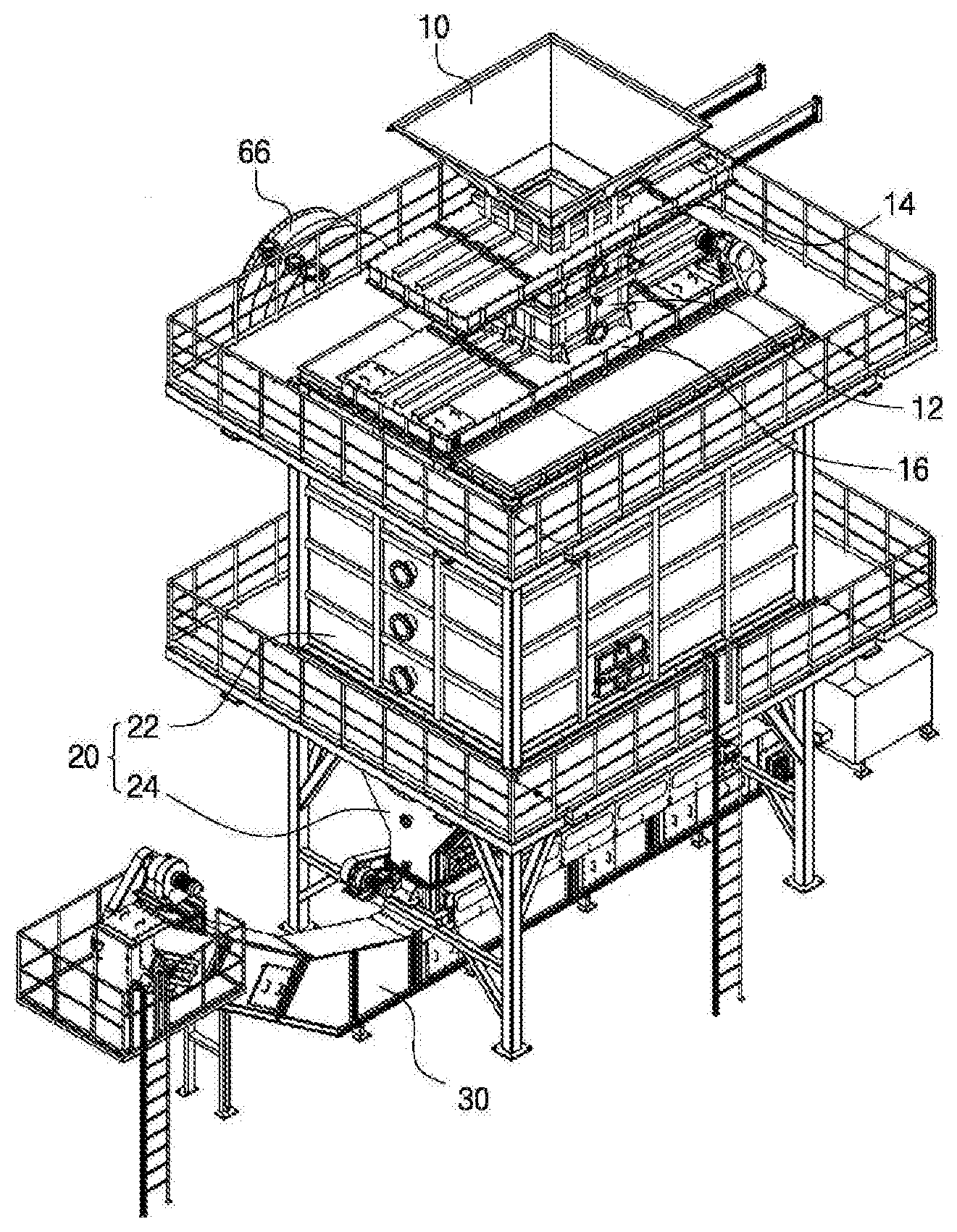
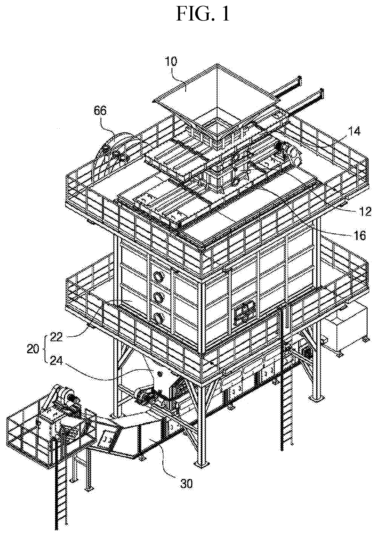
3. The system of claim 1, wherein the second sealing gate includes: a door member provided at a lower end of the loading chamber and configured to be linearly moved in a horizontal direction to open and close an inlet of the gas generating furnace; and a driving unit configured to linearly move the door member, wherein the driving unit includes: a wire connected to a front and a back of the door member; a drive roller disposed in front of the door member and configured such that the wire is wound therearound; a driven roller disposed behind the door member and configured such that the wire is wound therearound; and a drive motor connected to the drive roller to rotate the drive roller.
4. The system of claim 1, wherein the oxygen supply unit includes: a first nozzle configured such that multiple nozzles are provided on a wall of a lower gas generating furnace while being spaced apart from each other at a predetermined interval to uniformly supply oxygen into the lower gas generating furnace; a second nozzle configured to inject oxygen directly toward a bunting portion of the raw material by increasing injection pressure compared to the first nozzle; a first supply path provided on an outer wall of the lower gas generating furnace and connected to the first nozzle to supply oxygen to the first nozzle; and a second supply path connected to the second nozzle to supply oxygen to the second nozzle.
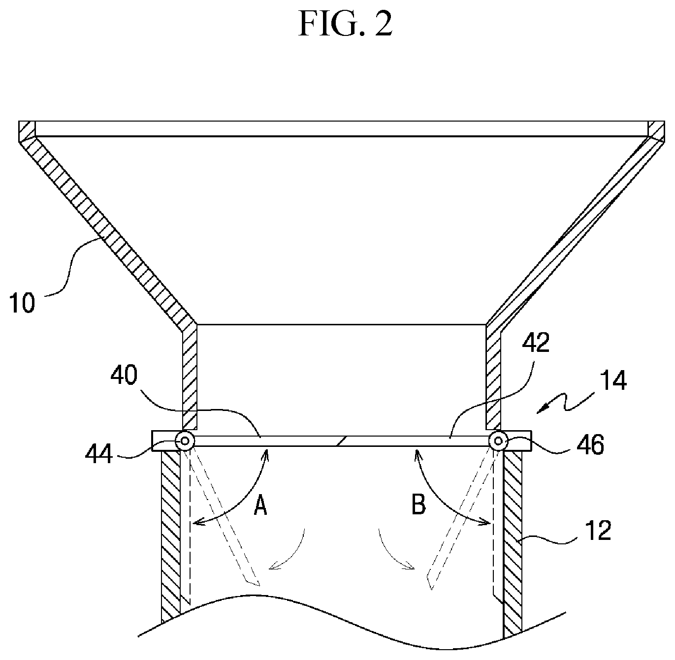
5. The system of claim 4, wherein the first nozzle is provided with a first nozzle passage, and the first nozzle passage is provided at an end portion thereof with a first nozzle opening opened at a predetermined angle such that the oxygen injected into the first nozzle passage diffuses into the gas generating furnace.
6. The system of claim 5, wherein the second nozzle is inserted into the first nozzle passage, and is provided with a second nozzle passage having a diameter smaller than a diameter of the first nozzle passage, and the second nozzle passage is provided at an end portion thereof with a second nozzle opening formed to be narrower than the second nozzle passage so as to increase oxygen injection pressure.
7. The system of claim 1, wherein the ash discharge unit includes: a drum rotatably provided in an ash outlet formed at a lower end of a lower gas generating furnace to discharge ash; a belt conveyor disposed at a location below the drum to move the ash discharged through the drum; and a water chamber provided at a lower portion of the lower gas generating furnace with water filled therein, and configured such that an end portion of the ash outlet of the lower gas generating furnace is sunken under the water to prevent external air from entering the gas generating furnace through the ash outlet.
8. The system of claim 7, wherein the drum is provided with inflow grooves at predetermined intervals to receive ash therein, and a drive shaft of the drum is connected to a drive motor.
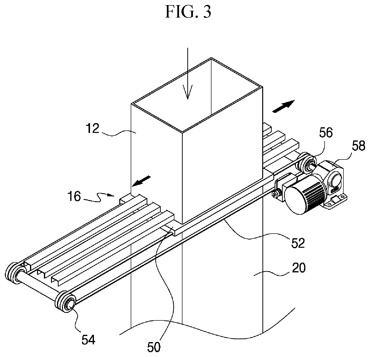
9. The system of claim 7, wherein the belt conveyor is provided in the water chamber and disposed to be sunken under the water.
Description
BACKGROUND OF THE INVENTION
Field of the Invention
[0001] The present invention relates to a pyrolysis gasification system capable of producing syngas, from which chemical products such as fuel gas or methanol are produced, by pyrolyzing raw material in a gas generating furnace.
Description of the Related Art
[0002] Generally, an incinerator currently used generates a large amount of ash, which is a residue after incineration. The characteristics of incineration ash are unstable, so that contaminants such as heavy metals may be released, and since a large amount of gas is generated during incineration, costs are high for removal of environmentally harmful substances such as dust, sulfur compounds, and nitrogen oxides.
[0003] To solve this problem, a pyrolysis incinerator has been developed that minimizes environmental pollutants generated during incineration and minimizes fumes by completely combusting raw material by pyrolysis.
[0004] The conventional pyrolysis incineration apparatus, as disclosed in the document of Korean Patent No. 10-1483751 (registered Jan. 12, 2015), includes: a combustion unit configured to combust an object to be incinerated fed thereinto at a high temperature; a blowing unit provided in the combustion unit for forcibly blowing outside air into the combustion unit to introduce the outside air into the combustion unit; an auxiliary fuel injection unit provided in the combustion unit for injecting auxiliary fuel into the combustion unit to facilitate treatment of residue of the object with a high water content, wherein the combustion unit is configured such that a plurality of heat pipes are provided on an inner side wall thereof to produce hot water and hot air by using high temperature heat generated during incineration of the object, and the blowing unit includes: at least one blowing pipe provided on the inner side wall of the combustion unit and configured to blow the air into the combustion unit; an air inflow path provided in the combustion unit to be connected to the blowing pipe and formed with an air inlet; and a blowing fan provided to be connected to the air inflow path and configured to forcibly blow the air to the air inflow path through the air inlet.
[0005] However, the conventional incineration apparatus is problematic in that since it injects outside air into the combustion chamber, the content of carbon monoxide and hydrogen in the syngas produced thereafter is lowered due to the nitrogen contained in the air.
[0006] In addition, the conventional incineration apparatus is problematic in that since the inside of the combustion chamber cannot be sealed, the combustion gas in the combustion chamber may flow out to the outside, and outside air may be introduced into the combustion chamber.
[0007] The foregoing is intended merely to aid in the understanding of the background of the present invention, and is not intended to mean that the present invention falls within the purview of the related art that is already known to those skilled in the art.
DOCUMENTS OF RELATED ART
[0008] (Patent Document 1) Korean Patent No. 10-1483751 (registered Jan. 12, 2015)
SUMMARY OF THE INVENTION
[0009] Accordingly, the present invention has been made keeping in mind the above problems occurring in the related art, and it is an object of the present invention to provide a pyrolysis gasification system, which is configured to supply oxygen into the gas generating furnace so as to increase the content and concentration of carbon monoxide and hydrogen in combustion gas generated during pyrolysis, whereby the production of syngas for producing chemicals such as fuels for electricity production or methanol can be improved.
[0010] Further, it is another object of the present invention to provide a pyrolysis gasification system, in which the inside of the gas generating furnace is sealed such that combustion gas in the gas generating furnace is prevented from being discharged to the outside and external air is prevented from entering the gas generating furnace, whereby it is possible to prevent the harmful exhaust gas from flowing out and possible to improve production of syngas.
[0011] In order to achieve the above object, according to some aspect of the present invention, there is provided a pyrolysis gasification system including: a hopper configured such that raw material is fed thereinto; a loading chamber configured such that the raw material fed into the hopper is temporarily stored therein; a gas generating furnace configured such that the raw material stored in the loading chamber is fed thereinto, and pyrolyzed and incinerated; an ash discharge unit configured to discharge ash completely pyrolyzed in the gas generating furnace; and an oxygen supply unit configured to supply oxygen into the gas generating furnace, wherein the loading chamber is provided at an upper end thereof with a first sealing gate to seal the loading chamber, and the gas generating furnace is provided at an upper portion thereof with a second sealing gate to seal the gas generating furnace, such that when the raw material is fed into the gas generating furnace, external air is prevented from entering the gas generating furnace and combustion gas in the gas generating furnace is prevented from being discharged to an outside.
[0012] The first sealing gate may include: a first door rotatably provided on a first side of the upper end of the loading chamber by a first hinge rod; and a second door rotatably provided on a second side of the upper end of the loading chamber by a second hinge rod, and disposed to face the first door, wherein the first hinge rod and the second hinge rod are rotated by an elastic force of a spring or a drive motor.
[0013] The second sealing gate may include: a door member provided at a lower end of the loading chamber and configured to be linearly moved in a horizontal direction to open and close an inlet of the gas generating furnace; and a driving unit configured to linearly move the door member, wherein the driving unit includes: a wire connected to a front and a back of the door member; a drive roller disposed in front of the door member and configured such that the wire is wound therearound; a driven roller disposed behind the door member and configured such that the wire is wound therearound; and a drive motor connected to the drive roller to rotate the drive roller.
[0014] The oxygen supply unit may include: a first nozzle configured such that multiple nozzles are provided on a wall of a lower gas generating furnace while being spaced apart from each other at a predetermined interval to uniformly supply oxygen into the lower gas generating furnace; a second nozzle configured to inject oxygen directly toward a burning portion of the raw material by increasing injection pressure compared to the first nozzle; a first supply path provided on an outer wall of the lower gas generating furnace and connected to the first nozzle to supply oxygen to the first nozzle; and a second supply path connected to the second nozzle to supply oxygen to the second nozzle.
[0015] The first nozzle may be provided with a first nozzle passage, and the first nozzle passage may be provided at an end portion thereof with a first nozzle opening opened at a predetermined angle such that the oxygen injected into the first nozzle passage diffuses into the gas generating furnace.
[0016] The second nozzle may be inserted into the first nozzle passage, and may be provided with a second nozzle passage having a diameter smaller than a diameter of the first nozzle passage, and the second nozzle passage may be provided at an end portion thereof with a second nozzle opening formed to be narrower than the second nozzle passage so as to increase oxygen injection pressure.
[0017] The ash discharge unit may include: a drum rotatably provided in an ash outlet formed at a lower end of a lower gas generating furnace to discharge ash; a belt conveyor disposed at a location below the drum to move the ash discharged through the drum; and a water chamber provided at a lower portion of the lower gas generating furnace with water filled therein, and configured such that an end portion of the ash outlet of the lower gas generating furnace is sunken under the water to prevent external air from entering the gas generating furnace through the ash outlet.
[0018] The drum may be provided with inflow grooves at predetermined intervals to receive ash therein, and a drive shaft of the drum may be connected to a drive motor.
[0019] The belt conveyor may be provided in the water chamber and disposed to be sunken under the water.
[0020] According to the pyrolysis gasification system of the present invention configured as described above, it is advantageous in that it is configured to supply oxygen into the gas generating furnace so as to increase the content and concentration of carbon monoxide and hydrogen in combustion gas generated during pyrolysis, whereby the production of syngas for producing chemicals such as fuels for electricity production or methanol can be improved.
[0021] It is further advantageous in that the inside of the gas generating furnace is sealed such that combustion gas in the gas generating furnace is prevented from being discharged to the outside and external air is prevented from entering the gas generating furnace, whereby it is possible to prevent the harmful exhaust gas from flowing out and possible to improve production of syngas.
BRIEF DESCRIPTION OF THE DRAWINGS
[0022] The above and other objects, features and other advantages of the present invention will be more clearly understood from the following detailed description when taken in conjunction with the accompanying drawings, in which:
[0023] FIG. 1 is a perspective view showing a pyrolysis gasification system according to an embodiment of the present invention;
[0024] FIG. 2 is a sectional view showing a first sealing gate according to the embodiment of the present invention;
[0025] FIG. 3 is a perspective view showing a second sealing gate according to the embodiment of the present invention;
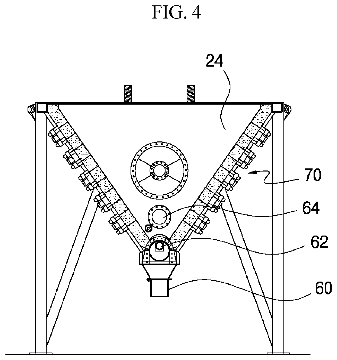
[0026] FIG. 4 is a sectional view showing a gas generating furnace according to the embodiment of the present invention;
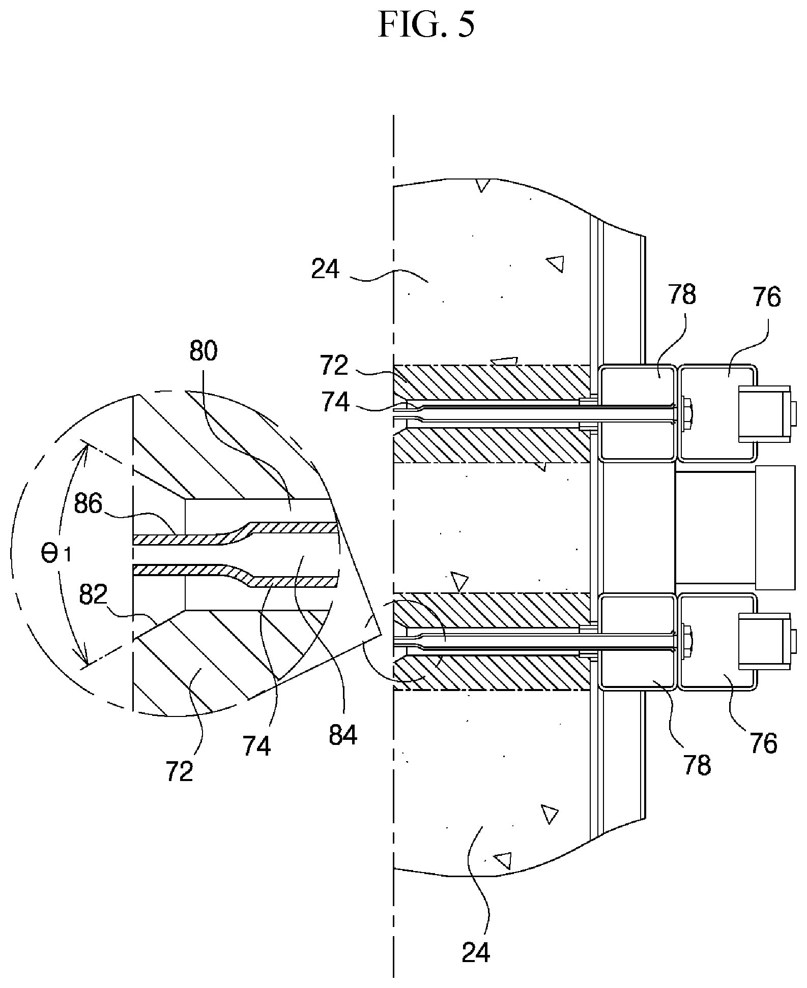
[0027] FIG. 5 is a sectional view showing an oxygen supply unit according to the embodiment of the present invention; and
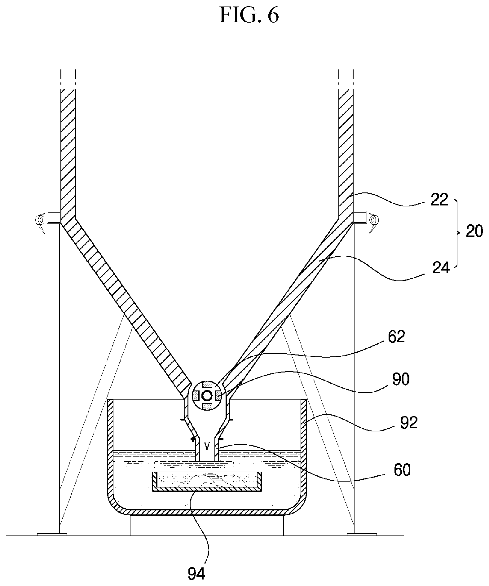
[0028] FIG. 6 is a sectional view showing an ash discharge unit according to the embodiment of the present invention.
DETAILED DESCRIPTION OF THE INVENTION
[0029] Hereinafter, embodiments of the present invention will be described in detail with reference to the accompanying drawings. In this process, the size and shape of the components shown in the drawings may be exaggerated for clarity and convenience of explanation. In addition, terms defined in consideration of the configuration and operation of the present invention may be changed depending on the intention or custom of the user or the operator. Definitions of these terms should be based on the contents throughout this specification.
[0030] FIG. 1 is a perspective view showing a pyrolysis gasification system according to an embodiment of the present invention.
[0031] Referring to FIG. 1, a pyrolysis gasification system of the present invention includes: a hopper 10 configured such that raw material is fed thereinto; a loading chamber 12 configured such that the raw material fed into the hopper 10 is temporarily stored therein; a gas generating furnace 20 configured such that the raw material stored in the loading chamber 12 is fed thereinto, and pyrolyzed and incinerated; an ash discharge unit 30 configured to discharge ash completely pyrolyzed in the gas generating furnace 20; and an oxygen supply unit configured to supply oxygen into the gas generating furnace 20.
[0032] Between the hopper 10 and the loading chamber 12, a first sealing gate 14 is provided to seal between the hopper 10 and the loading chamber 12. Further, between the loading chamber 12 and the gas generating furnace 20, a second sealing gate 16 is provided to seal between the loading chamber 12 and the gas generating furnace 20.
[0033] The first sealing gate 14, as shown in FIG. 2, includes: a first door 40 rotatably provided on a first side of the upper end of the loading chamber 12 by a first hinge rod 44; and a second door 42 rotatably provided on a second side of the upper end of the loading chamber 12 by a second hinge rod 46, and disposed to face the first door 40.
[0034] Each of the first hinge rod 44 and the second hinge rod 46 is provided with a spring providing an elastic force in a direction where the first door 40 and the second door 42 are closed, wherein the first door 40 and the second door 42 are opened while overcoming the elastic force of the spring by the weight of the raw material fed into the hopper 10, and the raw material fed into the hopper 10 is fed into the loading chamber 12 and the first door 40 and the second door 42 are automatically closed by the elastic force of the spring.
[0035] Further, other than this structure, the first hinge rod 44 and the second hinge rod 46 may be connected to a drive motor by gear engagement, a belt, or a chain, wherein when the drive motor rotates, the first hinge rod 44 and the second hinge rod 46 are rotated, whereby the first door 40 and the second door 42 are opened and closed.
[0036] The first door 40 is rotated as indicated by the arrow A, and the second door 42 is rotated as indicated by the arrow B so as to open and close the upper portion of the loading chamber 12. Here, at the edges of the first door 40 and the second door 42, or at the upper end of the loading chamber, a sealing member may be provided to perform a sealing function.
[0037] The second sealing gate 16, as shown in FIG. 3, includes: a door member 50 provided at a lower end of the loading chamber 12 and configured to be linearly moved in a horizontal direction to open and close an inlet of the gas generating furnace 20 into which the raw material is fed; and a driving unit configured to linearly move the door member 50.
[0038] Between the door member 50 and the lower end of the loading chamber, a guide member is provided to guide the door member to be linearly moved.
[0039] Further, the driving unit includes: a wire 52 connected to a front and a back of the door member 50; a drive roller 54 disposed in front of the door member 50 and configured such that the wire 52 is wound therearound; a driven roller 56 disposed behind the door member 50 and configured such that the wire 52 is wound therearound; and a drive motor 58 connected to the drive roller 54 to rotate the drive roller 54.
[0040] Herein, other than the above described structure, the driving unit may be any driving unit that can move the door member linearly, such as lead screw type.
[0041] The second sealing gate 16 is configured such that when the drive motor is driven, the wire is moved, and the door member 50 connected to the wire is moved, thereby sealably opening and closing the inlet of the gas generating furnace 20.
[0042] As described above, as for the raw material feeding path of the pyrolysis gasification system of the present invention, firstly, when the raw material is fed into the hopper 10, the raw material fed into the hopper 10 is temporarily stored in the loading chamber 12 as the first sealing gate 14 is opened.
[0043] Here, since the second sealing gate 16 is in the closed state, the gas generating furnace remains sealed.
[0044] Further, as the first sealing gate 14 is closed, the inside of the loading chamber 12 becomes sealed. Then, the second sealing gate 16 is opened. Accordingly, the raw material stored in the loading chamber 12 is fed through the inlet of the gas generating furnace 20. Here, since the loading chamber 12 is in the sealed state by the first sealing gate 14, external air can be prevented from entering the gas generating furnace 20 when the raw material is fed into the gas generating furnace 20.
[0045] The gas generating furnace 20 includes: an upper gas generating furnace 22 formed in a rectangular barrel shape and provided with the second sealing gate on the upper surface thereof, and a lower gas generating furnace 24 disposed below the upper gas generating furnace 22 and formed in an inverted triangular shape with the inner diameter thereof being gradually decreased toward the lower direction
[0046] The upper gas generating furnace 22 is formed in a square box shape having open top and bottom ends, and is provided on a side thereof with gas discharge duct 66 through which syngas is discharged, and a carbon monoxide inlet duct into which carbon monoxide is flowed.
[0047] The lower gas generating furnace 24, as shown in FIG. 4, is formed in a shape that the cross section thereof is in an inverted triangular shape and the inner diameter thereof is gradually decreased toward the lower side, and is provided with a burner 64 on a side thereof, and an ash outlet 60 on a lower surface thereof through which ash is discharged.
[0048] On the opposite sides of the lower gas generating furnace 24, the oxygen supply unit 70 is provided to supply oxygen into the gas generating furnace, and at the lower portion of the lower gas generating furnace 24, the ash discharge unit 30 is provided to discharge ash generated in the gas generating furnace 20.
[0049] The oxygen supply unit 70, as shown in FIGS. 5 and 6, includes: a first nozzle 72 configured such that multiple nozzles are provided on the opposite walls of the lower gas generating furnace 24 while being spaced apart from each other at a predetermined interval to uniformly supply oxygen into the lower gas generating furnace 24; a second nozzle 74 configured to inject oxygen directly toward a burning portion of the raw material by increasing injection pressure compared to the first nozzle 72; a first supply path 76 connected to the first nozzle 72 to supply oxygen to the first nozzle 72; and a second supply path 78 connected to the second nozzle 74 to supply oxygen to the second nozzle 74.
[0050] The first nozzle 72 is formed through the lower gas generating furnace 24, and is provided with a first nozzle passage 80 having a large diameter, wherein the end portion of the first nozzle passage 80 is provided with a first nozzle opening 82 opened at a predetermined angle .theta. such that the oxygen injected into the first nozzle passage 80 diffuses into the gas generating furnace. Herein, it is preferable that the angle .theta. of the first nozzle opening 82 is set to about 60 degrees.
[0051] The second nozzle 74 is inserted into the first nozzle passage 80, and is provided with a second nozzle passage 84 having a diameter smaller than that of the first nozzle passage 80, wherein the end portion of the second nozzle passage is provided with a second nozzle opening 86 formed to be narrower than the second nozzle passage 84 so as to increase oxygen injection pressure.
[0052] Since the first nozzle 72 has a low injection pressure, the first nozzle serves to supply oxygen uniformly throughout the gas generating furnace 24, and the second nozzle 74 has a high injection pressure of oxygen such that oxygen is directly supplied toward a burning portion of the raw material.
[0053] As described above, the oxygen supply unit of the present invention is configured such that oxygen supply pressures of the first nozzle 72 and the second nozzle 74 are different from each other, whereby in the first nozzle 72, oxygen is uniformly distributed throughout the entire gas generating furnace, and in the second nozzle 74, oxygen is directly injected toward the location where the raw material is burning, thereby allowing complete combustion to occur.
[0054] The pyrolysis gasification system produces syngas by pyrolysis and incineration of raw material, and the syngas is post-treated to produce methanol or used as a fuel gas to produce electricity.
[0055] A conventional pyrolysis incineration apparatus is problematic in that when air is injected into the gas generating furnace, the quality of the syngas produced is deteriorated due to the nitrogen contained in the air. To solve this problem, the present invention is configured to supply oxygen into the gas generating furnace, thereby improving the quality of syngas and the rate of complete combustion of raw material.
[0056] Further, a carbon monoxide inlet duct is connected to the gas generating furnace 20 to feed the carbon monoxide, which is remained after producing fuel gas or methanol by processing the syngas discharged from the gas generating furnace 20, back into the gas generating furnace, thereby preventing environmental pollution.
[0057] The ash discharge unit, as shown in FIG. 6, includes: a drum 62 rotatably provided in the ash outlet 60 formed at a lower end of the lower gas generating furnace to discharge ash; a belt conveyor 94 disposed at a location below the drum 62 to move the ash discharged through the drum 62; and a water chamber 92 provided at a lower portion of the lower gas generating furnace 24 with water filled therein, and configured such that an end portion of the ash outlet 60 of the lower gas generating furnace 24 is sunken under the water to prevent external air from entering the gas generating furnace 20 through the ash outlet 60.
[0058] The drum 62 is provided with inflow grooves 90 at predetermined intervals in the longitudinal direction to receive ash therein, and is connected with a drive motor, such that when the drum 62 is rotated by the drive motor, the ash in the inflow grooves 90 falls downward and is loaded on the belt conveyor 94.
[0059] Here, since the belt conveyor 94 is provided in the water chamber 92 and disposed under the water, the ash is discharged under the water, thereby preventing dust from floating.
[0060] Although a preferred embodiment of the present invention has been described for illustrative purposes, those skilled in the art will appreciate that various modifications, additions and substitutions are possible, without departing from the scope and spirit of the invention as disclosed in the accompanying claims.
* * * * *
D00000
D00001
D00002
D00003
D00004
D00005
D00006
XML
uspto.report is an independent third-party trademark research tool that is not affiliated, endorsed, or sponsored by the United States Patent and Trademark Office (USPTO) or any other governmental organization. The information provided by uspto.report is based on publicly available data at the time of writing and is intended for informational purposes only.
While we strive to provide accurate and up-to-date information, we do not guarantee the accuracy, completeness, reliability, or suitability of the information displayed on this site. The use of this site is at your own risk. Any reliance you place on such information is therefore strictly at your own risk.
All official trademark data, including owner information, should be verified by visiting the official USPTO website at www.uspto.gov. This site is not intended to replace professional legal advice and should not be used as a substitute for consulting with a legal professional who is knowledgeable about trademark law.