Storage Box
Taylor; Curtis ; et al.
U.S. patent application number 16/546414 was filed with the patent office on 2020-02-27 for storage box. The applicant listed for this patent is IdeaStream Consumer Products, LLC. Invention is credited to Matthew Hanson, Daniel Perella, Curtis Taylor.
| Application Number | 20200062452 16/546414 |
| Document ID | / |
| Family ID | 69583379 |
| Filed Date | 2020-02-27 |


| United States Patent Application | 20200062452 |
| Kind Code | A1 |
| Taylor; Curtis ; et al. | February 27, 2020 |
Storage Box
Abstract
The present disclosure relates to storage boxes commonly used to organize and store items such as school-related supplies that may be carried by a student. The storage boxes generally include a lid and a base. The base includes a divider which provides for two or more storage portions within an interior of the base, while also acting as a functional grip on the outside of the box. A latch mechanism is provided which securely latches the lid and base together in a closed configuration.
| Inventors: | Taylor; Curtis; (Chagrin Falls, OH) ; Perella; Daniel; (Hudson, OH) ; Hanson; Matthew; (Chagrin Falls, OH) | ||||||||||
| Applicant: |
|
||||||||||
|---|---|---|---|---|---|---|---|---|---|---|---|
| Family ID: | 69583379 | ||||||||||
| Appl. No.: | 16/546414 | ||||||||||
| Filed: | August 21, 2019 |
Related U.S. Patent Documents
| Application Number | Filing Date | Patent Number | ||
|---|---|---|---|---|
| 62720282 | Aug 21, 2018 | |||
| Current U.S. Class: | 1/1 |
| Current CPC Class: | A45C 13/02 20130101; B65D 25/04 20130101; B65D 43/162 20130101; B65D 21/0223 20130101; B25H 3/02 20130101; B65D 25/20 20130101; A45C 11/34 20130101; B65D 43/22 20130101; B65D 25/2894 20130101; B65D 21/0233 20130101; A45C 13/1084 20130101 |
| International Class: | B65D 21/02 20060101 B65D021/02; B65D 25/04 20060101 B65D025/04; B65D 25/28 20060101 B65D025/28; B65D 25/20 20060101 B65D025/20; B65D 43/16 20060101 B65D043/16; B65D 43/22 20060101 B65D043/22 |
Claims
1. A storage box, comprising: a base with an open interior; a lid attached to the base; a closed configuration where the lid is closed against the base and an open configuration where the lid is moveable with respect to the base; a divider which separates the interior of the base into two or more storage areas; and, a recessed grip on an exterior surface of the base.
2. The storage box of claim 1, wherein the divider is integrally formed with the base.
3. The storage box of claim 1, wherein the grip is integrally formed with the base.
4. The storage box of claim 1, wherein the divider is comprised of one or more ridges formed on a bottom wall of the base and an underside of the one or more ridges defines the recessed grip on the exterior surface of the base.
5. The storage box of claim 1, wherein the recessed grip is comprised of one or more channels formed on a bottom wall of the base.
6. The storage box of claim 1, further comprising a ruler disposed on the exterior surface of the base and adjacent a lower portion thereof.
7. The storage box of claim 6, wherein the ruler is comprised of a plurality of indentations formed on the exterior surface of the base.
8. The storage box of claim 1, further comprising a latch mechanism configured to secure the lid and base in the closed configuration, the latch mechanism including a resiliently biased member disposed on the lid and a flat rim disposed on the base.
9. The storage box of claim 1, further comprising a hinge which connects at least one wall of the lid to at least one wall of the base.
10. The storage box of claim 1, further comprising a stop wall disposed on the base and one or more retaining walls disposed on the lid, wherein the one or more retaining walls are configured to engage the stop wall and prevent the lid from over-extending past the base in the closed configuration.
11. The storage box of claim 1, further comprising one or more stacking features configured to enable a stacked configuration of a plurality of storage boxes in the open configuration.
12. The storage box of claim 11, wherein the one or more stacking features includes one or more apertures and one or more retaining walls located on the lid, wherein the one or more apertures on a lid of an upper storage box in the plurality of open configuration storage boxes is configured to receive the one or more retaining walls on a lid of a lower storage box in the plurality of open configuration storage boxes.
13. The storage box of claim 11, wherein the one or more stacking features includes a ridge extending around at least a portion of a perimeter of the lid, wherein the ridge on a lid of an upper storage box in the plurality of open configuration storage boxes is configured to receive the ridge on a lid of a lower storage box in the plurality of open configuration storage boxes.
14. The storage box of claim 11, wherein the one or more stacking features includes an indent and a barb disposed on the lid, wherein the indent on a lid of an upper storage box in the plurality of open configuration storage boxes is configured to receive the barb on a lid of a lower storage box in the plurality of open configuration storage boxes.
15. A method of making a storage box, the method comprising: providing a base with an open interior and a lid attached to the base, wherein the lid is closed against the base in a closed configuration and the lid is moveable with respect to the base in an open configuration; dividing the interior of the base into two or more storage areas by forming one or more ridges on a bottom wall of the base; and, forming one or more channels on an exterior surface of the bottom wall of the base to provide a recessed grip.
16. The method of claim 15, further comprising: providing a plurality of storage boxes in a stacked configuration, wherein each storage box in the plurality is in the open configuration; forming one or more stacking features on the lid of each storage box in the plurality of storage boxes.
17. The method of claim 16, further comprising engaging the one or more stacking features on a lid of an upper box in the plurality of storage boxes with the one or more stacking features on a lid of a lower box in the plurality of storage boxes.
18. The method of claim 16, further comprising selecting the one or more stacking features on each lid in the plurality of storage boxes from at least one of: an indent and a barb, one or more apertures and one or more retaining walls and/or a ridge extending around a perimeter portion of the lid.
19. A storage box, comprising: a base with an open interior; a lid attached to the base with a hinge; a closed configuration where the lid is closed against the base and an open configuration where the lid is moveable with respect to the base; a latch mechanism configured to secure the lid and base in the closed configuration; one or more ridges formed in the base which divide the interior into two or more storage areas; a recessed grip on an exterior surface of the base which is defined by an underside of the one or more ridges; a ruler disposed on the exterior surface of the base, wherein the ruler is comprised of a plurality of indentations formed on the exterior surface of the base; and, one or more stacking features formed on the lid.
20. The storage box of claim 19, further comprising a plurality of storage boxes in a stacked configuration, wherein each storage box in the plurality is in the open configuration and wherein the one or more stacking features on each lid in the plurality of storage boxes are configured to engage with one another to maintain the stacked configuration of the plurality of storage boxes.
Description
CROSS REFERENCE TO RELATED APPLICATIONS
[0001] This application claims priority to U.S. Provisional Application No. 62/720,282, filed Aug. 21, 2018, the disclosure of which is herein incorporated by reference in its entirety.
SUMMARY
[0002] The present disclosure relates to storage boxes commonly used to organize and store items, such as school-related supplies that may be carried by a student. The storage boxes generally include a lid and a base. The base includes a divider which provides for two or more storage portions within an interior of the base, while also acting as a functional grip on the outside of the box. A latch mechanism is provided which securely latches the lid and base together in a closed configuration.
BACKGROUND
[0003] There are a variety of storage devices used by students in the marketplace today for storing and organizing items such as school-related supplies. A two-piece lid and base box are fairly common components of a device used for such storage and organization. Existing storage boxes are often provided with only one common interior storage portion, making organization difficult. Other existing storage boxes have attempted to provide dividers within the interior storage portion; however, these existing boxes have sacrificed capacity to do so. Moreover, known storage boxes used in the marketplace today can be difficult to grip, especially by users with smaller hands, such as young school children.
[0004] In view of the prior art, there remains a need for a novel storage box that provides sufficient organization without sacrificing capacity and/or provides sufficient grip to the outside of the box.
BRIEF DESCRIPTION OF THE INVENTION
[0005] The present disclosure is directed to storage boxes commonly used to organize and store school-related supplies that may be carried by a student. Such storage boxes may also commonly be referred to as pencil boxes; however, any desired item that can fit within the storage box could also be stored/organized (e.g., pens, erasers, scissors, crayons, markers, etc.).
[0006] In one non-limiting aspect of the present disclosure, the exemplary storage boxes include a lid component and a base component. A connection means attaches the lid to the base on at least one side thereof. In accordance with another non-limiting aspect of the present disclosure, the lid and base are configurable between an open configuration and a closed configuration.
[0007] In accordance with other non-limiting aspects of the disclosure, the base includes a divider configured to separate the interior of the box into two or more interior storage portions. In some non-limiting configurations, when the lid and base are in the closed configuration, the divider prevents items stored the two or more interior storage portions from moving into another one of the two or more interior storage portions. In this regard, the exemplary box advantageously maintains the organization of items stored in the box without sacrificing capacity.
[0008] In another non-limiting aspect of the disclosure, the divider on base of the presently described storage boxes is also adapted to provide a functional grip on the outside of the box.
[0009] In accordance with one non-limiting aspect of the disclosure, there is provided a storage box which includes a base with an open interior and a lid attached to the base. The storage box has a closed configuration where the lid is closed against the base and an open configuration where the lid is moveable with respect to the base. A divider is included which separates the interior of the base into two or more storage areas. The storage box also includes a recessed grip on an exterior surface of the base.
[0010] In some non-limiting aspects of the disclosure, the divider of the storage box is integrally formed with the base. In addition, the grip can also be integrally formed with the base.
[0011] In other non-limiting aspects of the disclosure, the divider is formed from one or more ridges on a bottom wall of the base and an underside of the one or more ridges defines the recessed grip on the exterior surface of the base. In accordance with additional non-limiting aspects, the recessed grip is formed from one or more channels on a bottom wall of the base.
[0012] In one non-limiting aspect of the disclosure, the storage box includes a ruler disposed on the exterior surface of the base and adjacent a lower portion thereof. The ruler can be made of a plurality of indentations formed on the exterior surface of the base.
[0013] In another non-limiting aspect of the disclosure, the storage box includes a latch mechanism configured to secure the lid and base in the closed configuration. The latch mechanism includes a resiliently biased member disposed on the lid and a flat rim disposed on the base.
[0014] In accordance with an additional non-limiting aspect of the disclosure, the storage box also includes a hinge which connects at least one wall of the lid to at least one wall of the base.
[0015] In accordance with other non-limiting aspects of the disclosure, the storage box has a stop wall disposed on the base and one or more retaining walls disposed on the lid. The one or more retaining walls are configured to engage the stop wall and prevent the lid from over-extending past the base in the closed configuration.
[0016] In some non-limiting aspects of the disclosure, the storage box includes one or more stacking features configured to enable a stacked configuration of a plurality of storage boxes in the open configuration.
[0017] In such non-limiting embodiments with one or more stacking features, the one or more stacking features include one or more apertures and one or more retaining walls located on the lid. The one or more apertures on a lid of an upper storage box in the plurality of open configuration storage boxes are configured to receive the one or more retaining walls on a lid of a lower storage box in the plurality of open configuration storage boxes.
[0018] In other non-limiting embodiments with one or more stacking features, the one or more stacking features include a ridge extending around at least a portion of a perimeter of the lid. The ridge on a lid of an upper storage box in the plurality of open configuration storage boxes is configured to receive the ridge on a lid of a lower storage box in the plurality of open configuration storage boxes.
[0019] In additional non-limiting embodiments with one or more stacking features, the one or more stacking features include an indent and a barb disposed on the lid. The indent on a lid of an upper storage box in the plurality of open configuration storage boxes is configured to receive the barb on a lid of a lower storage box in the plurality of open configuration storage boxes.
[0020] In accordance with a second non-limiting aspect of the disclosure, there is provided a method of making a storage box which includes 1) providing a base with an open interior and a lid attached to the base, wherein the lid is closed against the base in a closed configuration and the lid is moveable with respect to the base in an open configuration; 2) dividing the interior of the base into two or more storage areas by forming one or more ridges on a bottom wall of the base; and, 3) forming one or more channels on an exterior surface of the bottom wall of the base to provide a recessed grip.
[0021] In some non-limiting aspects of the disclosure, the method includes providing a plurality of storage boxes in a stacked configuration, wherein each storage box in the plurality is in the open configuration. The method also includes forming one or more stacking features on the lid of each storage box in the plurality of storage boxes.
[0022] In such non-limiting embodiments with one or more stacking features, the method further includes engaging the one or more stacking features on a lid of an upper box in the plurality of storage boxes with the one or more stacking features on a lid of a lower box in the plurality of storage boxes.
[0023] In additional non-limiting embodiments with one or more stacking features, the method also includes selecting the one or more stacking features on each lid in the plurality of storage boxes include at least one of an indent and a barb, one or more apertures and one or more retaining walls, and a ridge extending around a perimeter portion of the lid.
[0024] In accordance with a third non-limiting aspect of the disclosure, there is provided a storage box which includes a base with an open interior and a lid attached to the base with a hinge. In a closed configuration of the storage box, the lid is closed against the base. In an open configuration of the storage box, the lid is moveable with respect to the base. A latch mechanism configured to secure the lid and base in the closed configuration is also included. In addition, one or more ridges are formed in the base which divide the interior into two or more storage areas. Furthermore, a recessed grip on an exterior surface of the base is defined by an underside of the one or more ridges. A ruler is included which is disposed on the exterior surface of the base; and the ruler is comprised of a plurality of indentations formed on the exterior surface of the base. Finally, one or more stacking features are formed on the lid.
[0025] In such non-limiting embodiments with one or more stacking features, a plurality of storage boxes in a stacked configuration is also provided. Each storage box in the plurality is in the open configuration and the one or more stacking features on each lid in the plurality of storage boxes are configured to engage with one another to maintain the stacked configuration of the plurality of storage boxes.
[0026] In one non-limiting object of the invention, there is the provision of a storage box comprising 1) a base with an open interior; 2) a lid attached to the base; 3) a closed configuration where the lid is closed against the base and an open configuration where the lid is moveable with respect to the base; 4) a divider which separates the interior of the base into two or more storage areas; and, 5) a recessed grip on an exterior surface of the base.
[0027] In another non-limiting object of the invention, there is the provision of a storage box wherein the divider is integrally formed with the base.
[0028] In another non-limiting object of the invention, there is the provision of a storage box the grip is integrally formed with the base.
[0029] In another non-limiting object of the invention, there is the provision of a storage box wherein the divider is comprised of one or more ridges formed on a bottom wall of the base and an underside of the one or more ridges defines the recessed grip on the exterior surface of the base.
[0030] In another non-limiting object of the invention, there is the provision of a storage box wherein the recessed grip is comprised of one or more channels formed on a bottom wall of the base.
[0031] In another non-limiting object of the invention, there is the provision of a storage box further comprising a ruler disposed on the exterior surface of the base and adjacent a lower portion thereof.
[0032] In another non-limiting object of the invention, there is the provision of a storage box wherein the ruler is comprised of a plurality of indentations formed on the exterior surface of the base.
[0033] In another non-limiting object of the invention, there is the provision of a storage box further comprising a latch mechanism configured to secure the lid and base in the closed configuration, the latch mechanism including a resiliently biased member disposed on the lid and a flat rim disposed on the base.
[0034] In another non-limiting object of the invention, there is the provision of a storage box further comprising a hinge which connects at least one wall of the lid to at least one wall of the base.
[0035] In another non-limiting object of the invention, there is the provision of a storage box further comprising a stop wall disposed on the base and one or more retaining walls disposed on the lid, wherein the one or more retaining walls are configured to engage the stop wall and prevent the lid from over-extending past the base in the closed configuration.
[0036] In another non-limiting object of the invention, there is the provision of a storage box further comprising one or more stacking features configured to enable a stacked configuration of a plurality of storage boxes in the open configuration.
[0037] In another non-limiting object of the invention, there is the provision of a storage box wherein the one or more stacking features include one or more apertures and one or more retaining walls located on the lid, wherein the one or more apertures on a lid of an upper storage box in the plurality of open configuration storage boxes is configured to receive the one or more retaining walls on a lid of a lower storage box in the plurality of open configuration storage boxes.
[0038] In another non-limiting object of the invention, there is the provision of a storage box wherein the one or more stacking features includes a ridge extending around at least a portion of a perimeter of the lid, wherein the ridge on a lid of an upper storage box in the plurality of open configuration storage boxes is configured to receive the ridge on a lid of a lower storage box in the plurality of open configuration storage boxes.
[0039] In another non-limiting object of the invention, there is the provision of a storage box wherein the one or more stacking features includes an indent and a barb disposed on the lid, wherein the indent on a lid of an upper storage box in the plurality of open configuration storage boxes is configured to receive the barb on a lid of a lower storage box in the plurality of open configuration storage boxes.
[0040] In another non-limiting object of the invention, there is the provision of a method of making a storage box comprising: 1) providing a base with an open interior and a lid attached to the base, wherein the lid is closed against the base in a closed configuration and the lid is moveable with respect to the base in an open configuration; 2) dividing the interior of the base into two or more storage areas by forming one or more ridges on a bottom wall of the base; and, 3) forming one or more channels on an exterior surface of the bottom wall of the base to provide a recessed grip.
[0041] In another non-limiting object of the invention, there is the provision of a method of making a storage box further comprising: providing a plurality of storage boxes in a stacked configuration, wherein each storage box in the plurality is in the open configuration; and forming one or more stacking features on the lid of each storage box in the plurality of storage boxes.
[0042] In another non-limiting object of the invention, there is the provision of a method of making a storage box further comprising engaging the one or more stacking features on a lid of an upper box in the plurality of storage boxes with the one or more stacking features on a lid of a lower box in the plurality of storage boxes.
[0043] In another non-limiting object of the invention, there is the provision of a method of making a storage box further comprising selecting the one or more stacking features on each lid in the plurality of storage boxes from at least one of: an indent and a barb, one or more apertures and one or more retaining walls and/or a ridge extending around a perimeter portion of the lid.
[0044] In another non-limiting object of the invention, there is the provision of a storage box comprising 1) a base with an open interior; 2) a lid attached to the base with a hinge; 3) a closed configuration where the lid is closed against the base and an open configuration where the lid is moveable with respect to the base; 4) a latch mechanism configured to secure the lid and base in the closed configuration; 5) one or more ridges formed in the base which divide the interior into two or more storage areas; 6) a recessed grip on an exterior surface of the base which is defined by an underside of the one or more ridges; 7) a ruler disposed on the exterior surface of the base, wherein the ruler is comprised of a plurality of indentations formed on the exterior surface of the base; and, 8) one or more stacking features formed on the lid.
[0045] In another non-limiting object of the invention, there is the provision of a storage box further comprising a plurality of storage boxes in a stacked configuration, wherein each storage box in the plurality is in the open configuration and wherein the one or more stacking features on each lid in the plurality of storage boxes are configured to engage with one another to maintain the stacked configuration of the plurality of storage boxes.
[0046] These and other objects and advantages will become apparent from the discussion of the distinction between the invention and the prior art and when considering the preferred embodiment shown in the accompanying drawings.
BRIEF DESCRIPTION OF THE DRAWINGS
[0047] Reference may now be made to the drawings, which illustrate various embodiments that the invention may take in physical form and in certain parts and arrangements of parts wherein:
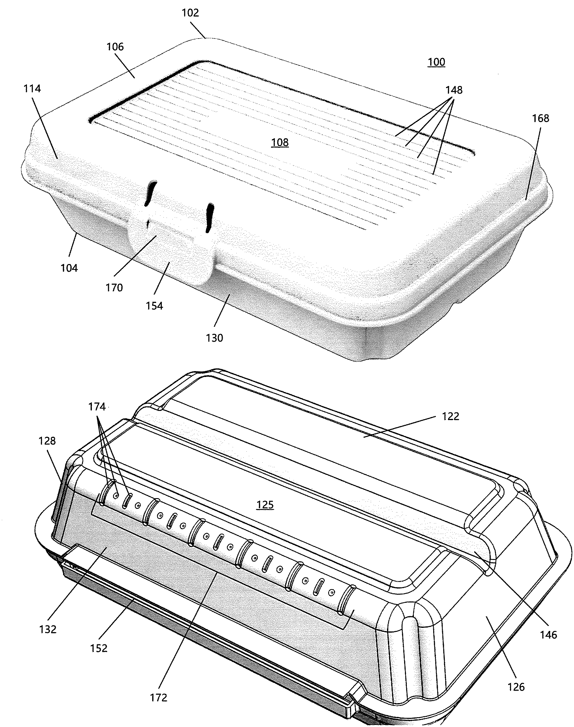
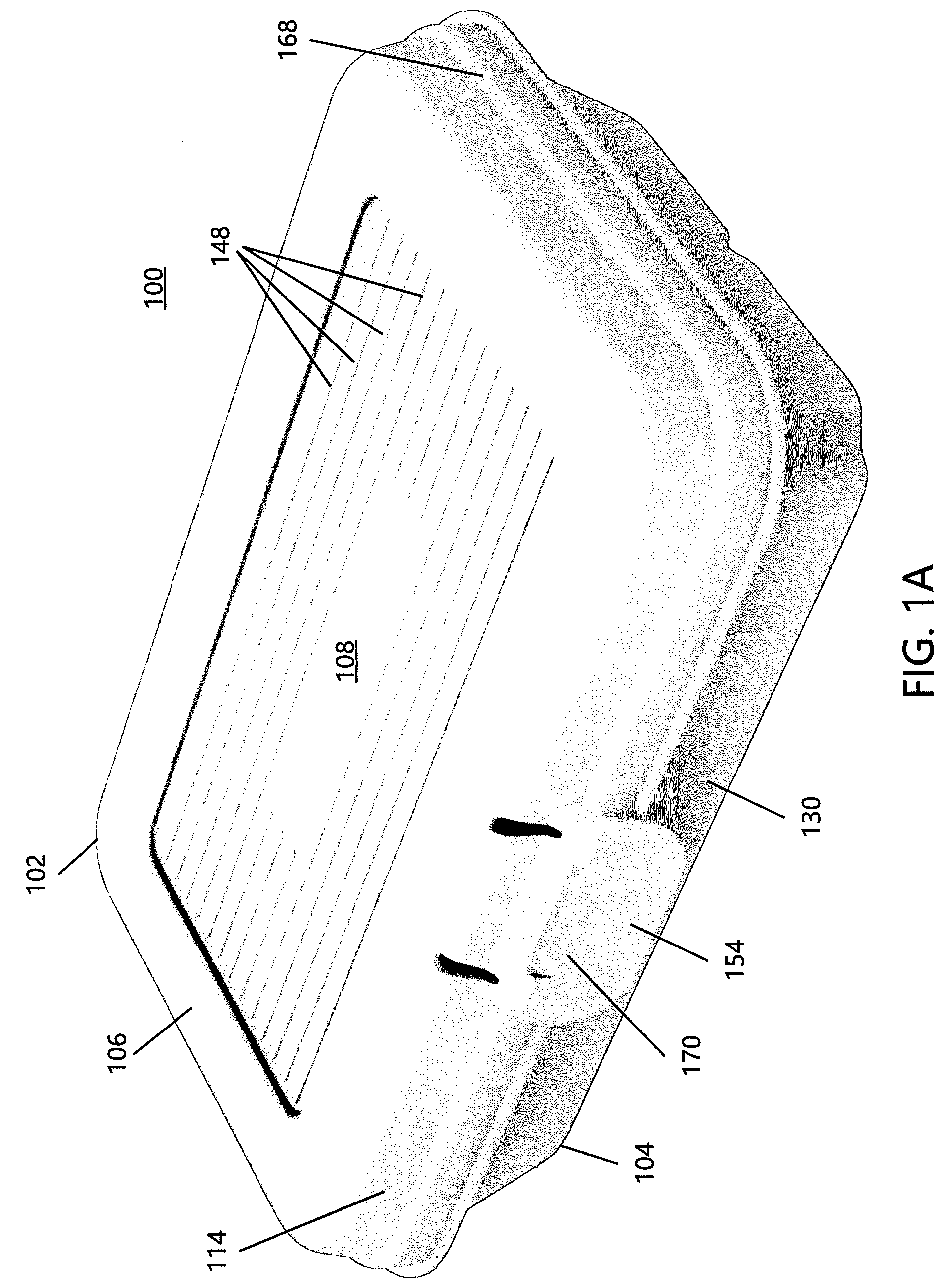
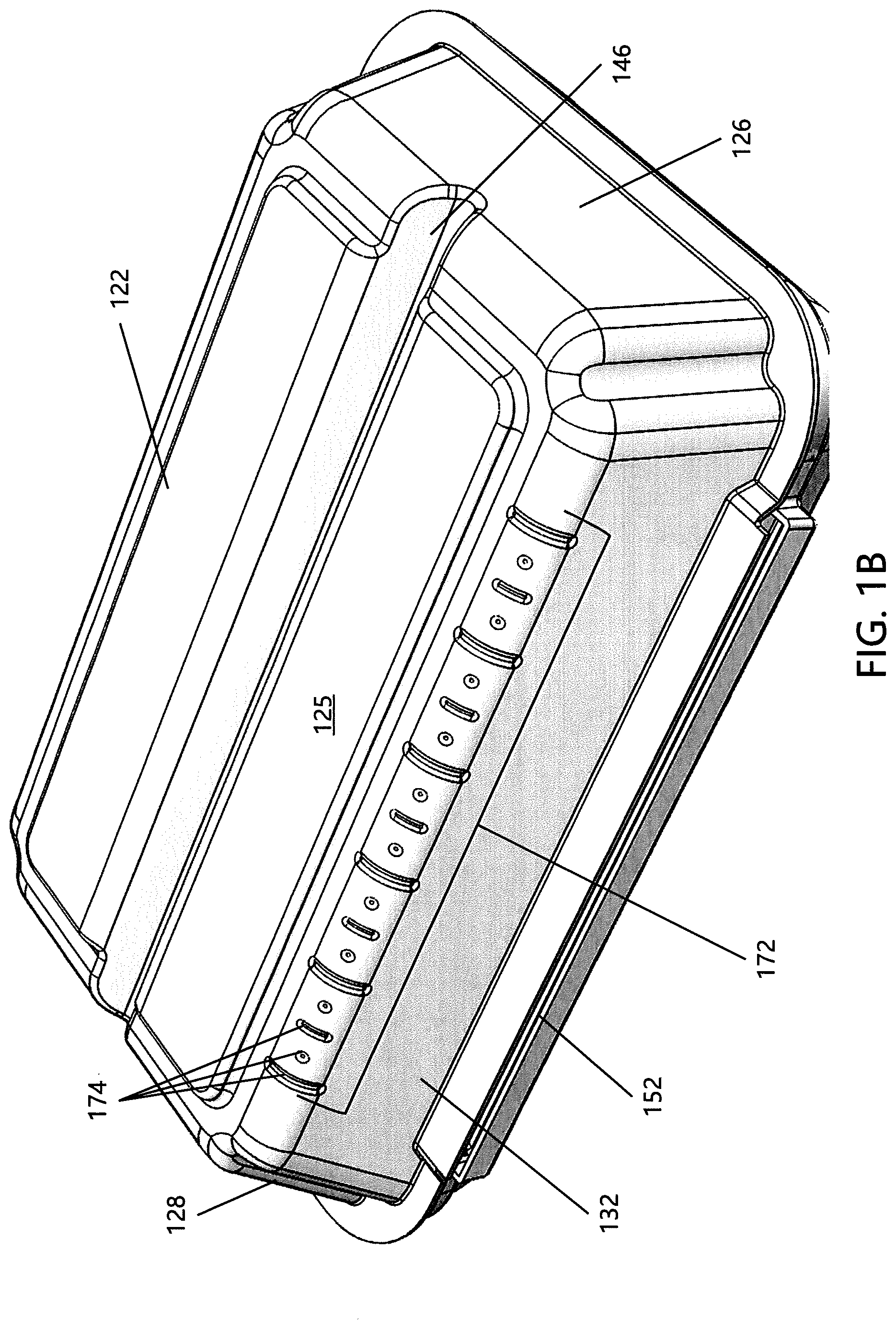
[0048] FIGS. 1A and 1B are illustrations according to one non-limiting embodiment of the present disclosure, where FIG. 1A shows a top perspective view of an exemplary storage box and FIG. 1B shows a bottom perspective view, where the storage box in both FIGS. 1A and 1B is in a closed configuration;
[0049] FIG. 2 is a detailed illustration of the storage box illustrated in FIGS. 1A and 1B which shows a close-up view of a latch mechanism thereof;
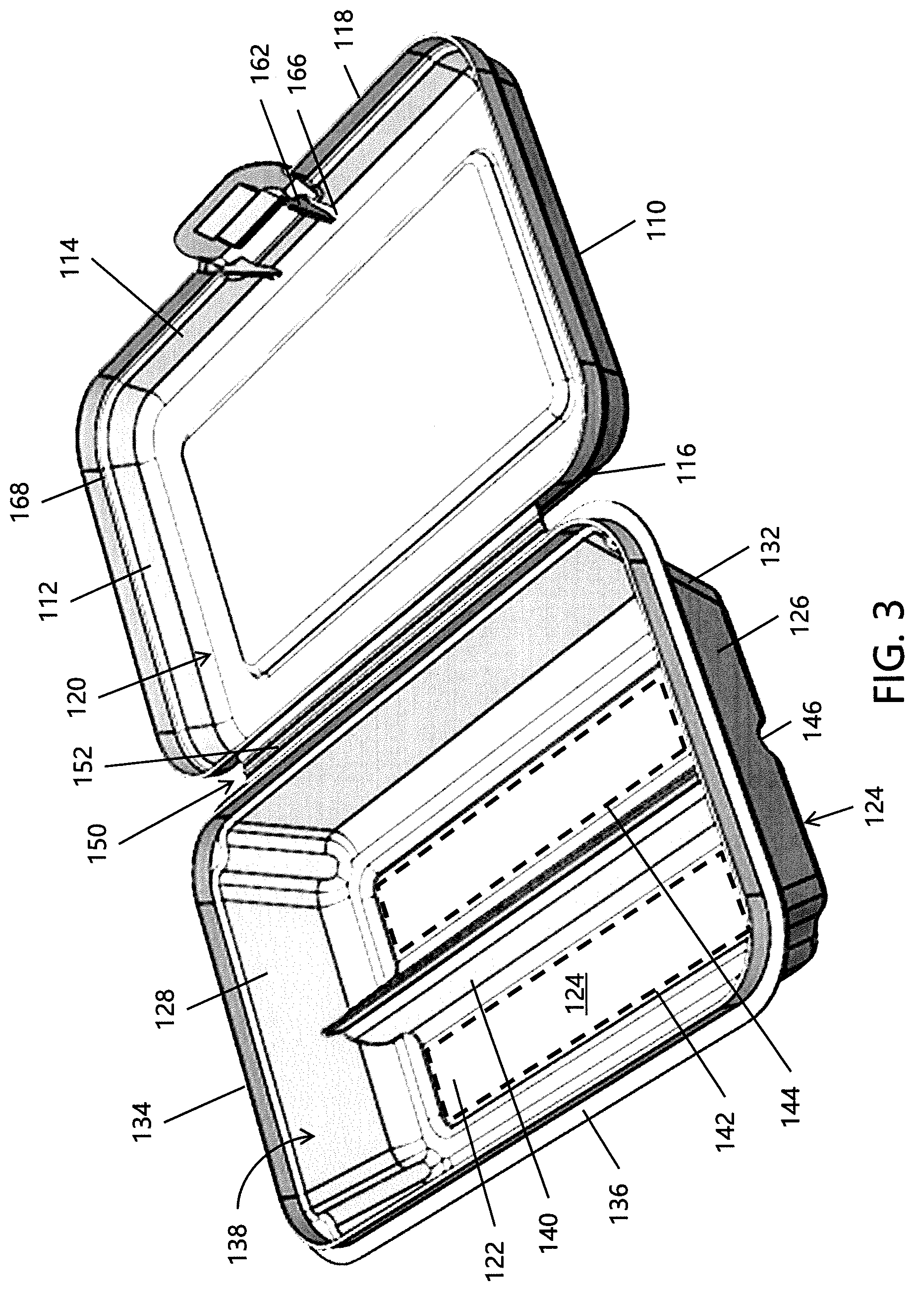
[0050] FIG. 3 is a perspective top view of the storage box illustrated in FIGS. 1A and 1B which shows the storage box in an open configuration;
[0051] FIG. 4 is a detailed illustration of the storage box illustrated in FIGS. 1A and 1B which shows a close-up view of a resiliently biased tab member of the latch mechanism illustrated in FIG. 2;
[0052] FIG. 5 is a partial cross-sectional side view of the storage box illustrated in FIGS. 1A and 1B which shows a detailed view of the latch mechanism when the storage box is in a closed configuration;
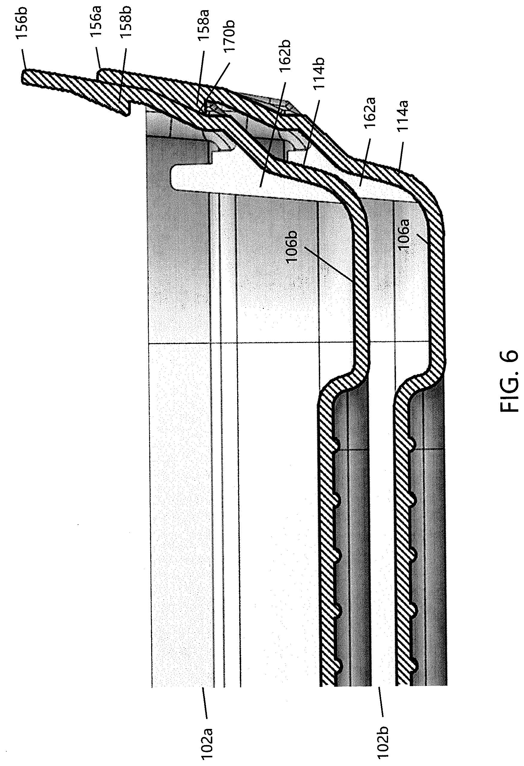
[0053] FIG. 6 is an illustration according to one non-limiting aspect of the present embodiment showing a partial cross-sectional side view of two storage boxes having the features of the storage box illustrated in FIGS. 1A and 1B, the two storage boxes being in a stacked/nested configuration;
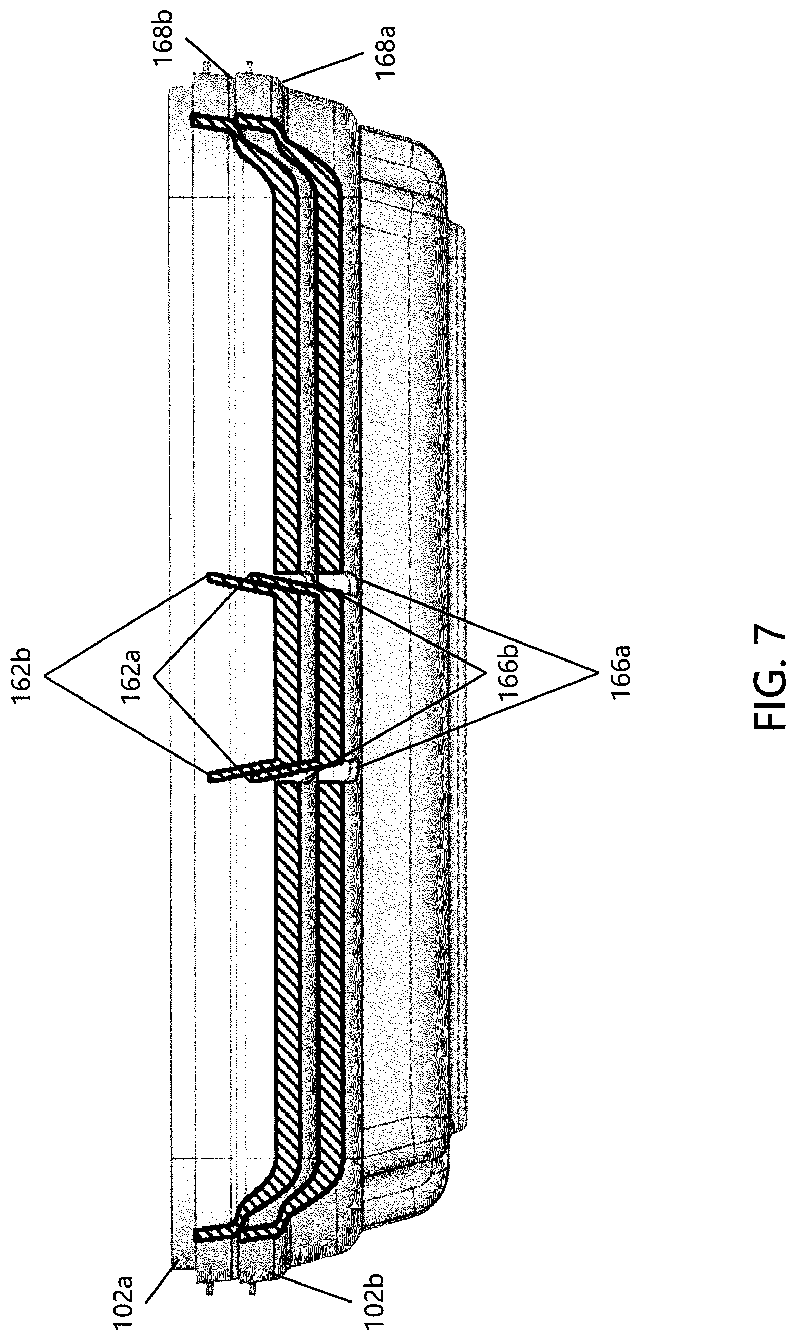
[0054] FIG. 7 is an illustration showing another view of the two storage boxes from FIG. 6; and,
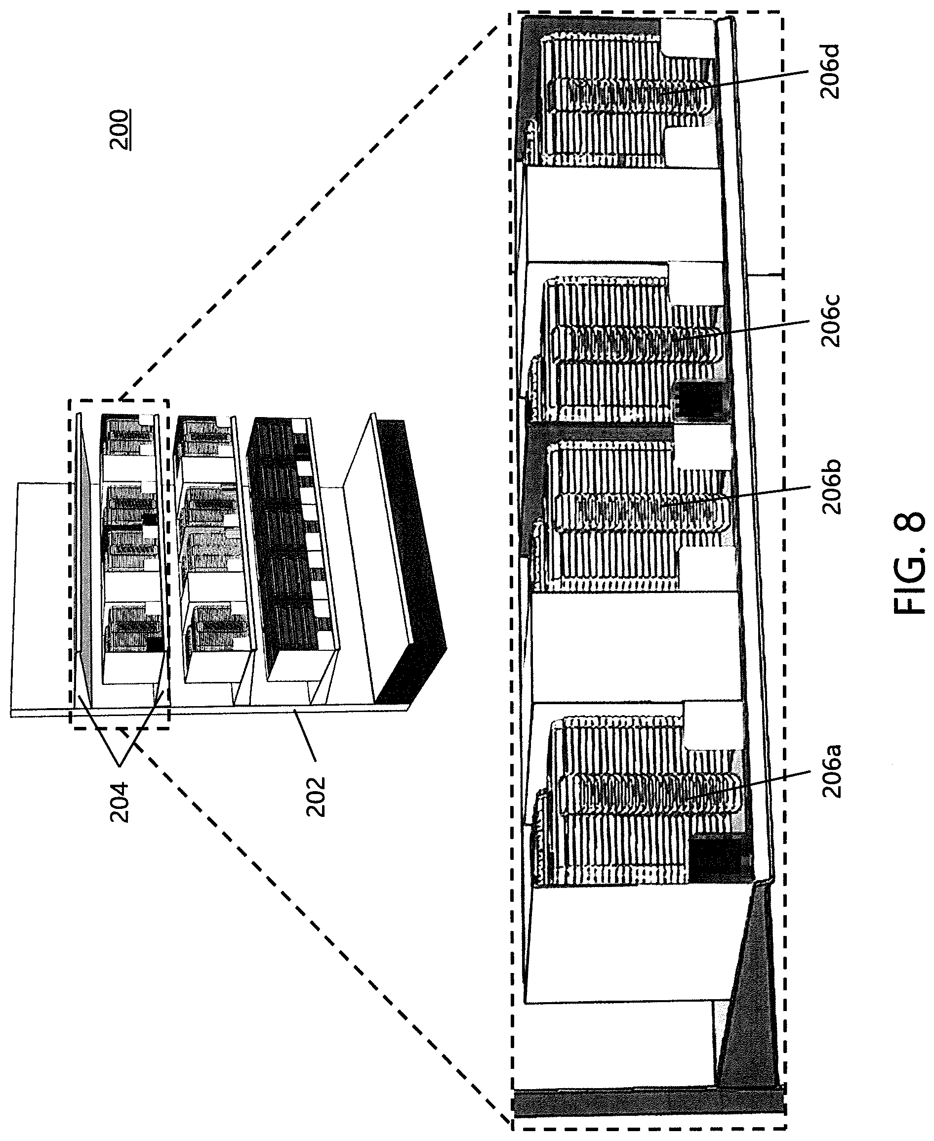
[0055] FIG. 8 is an illustration according to another non-limiting embodiment of the present disclosure, where a plurality of storage boxes in a stacked configuration, each having the features of the storage box illustrated in FIGS. 1A and 1B, are illustrated in a plurality of stacks on a shelf unit.
DETAILED DESCRIPTION
[0056] A more complete understanding of the articles/devices, processes, and components disclosed herein can be obtained by reference to the accompanying drawings. These figures are merely schematic representations based on convenience and the ease of demonstrating the present disclosure, and are, therefore, not intended to indicate relative size and dimensions of the devices or components thereof and/or to define or limit the scope of the exemplary embodiments.
[0057] Although specific terms are used in the following description for the sake of clarity, these terms are intended to refer only to the particular structure of the embodiments selected for illustration in the drawings and are not intended to define or limit the scope of the disclosure. In the drawings and the following description below, it is to be understood that like numeric designations refer to components of like function.
[0058] The singular forms "a," "an," and "the" include plural referents unless the context clearly dictates otherwise.
[0059] As used in the specification and in the claims, the term "comprising" may include the embodiments "consisting of" and "consisting essentially of." The terms "comprise(s)," "include(s)," "having," "has," "can," "contain(s)," and variants thereof, as used herein, are intended to be open-ended transitional phrases, terms, or words that require the presence of the named ingredients/steps and permit the presence of other ingredients/steps. However, such description should be construed as also describing compositions or processes as "consisting of" and "consisting essentially of" the enumerated ingredients/steps, which allows the presence of only the named ingredients/steps, along with any unavoidable impurities that might result therefrom, and excludes other ingredients/steps.
[0060] Numerical values in the specification and claims of this application should be understood to include numerical values which are the same when reduced to the same number of significant figures and numerical values which differ from the stated value by less than the experimental error of conventional measurement technique of the type described in the present application to determine the value.
[0061] All ranges disclosed herein are inclusive of the recited endpoint and independently combinable (for example, the range of "from 2 grams to 10 grams" is inclusive of the endpoints, 2 grams and 10 grams, and all the intermediate values).
[0062] The terms "about" and "approximately" can be used to include any numerical value that can vary without changing the basic function of that value. When used with a range, "about" and "approximately" also disclose the range defined by the absolute values of the two endpoints, e.g. "about 2 to about 4" also discloses the range "from 2 to 4." Generally, the terms "about" and "approximately" may refer to plus or minus 10% of the indicated number.
[0063] Referring now to FIGS. 1-7, there is illustrated a first non-limiting embodiment of a storage box 100. The primary components of the storage box 100 include, but are not limited to, a lid 102 and a base 104. A connection means 150 attaches the lid 102 to the base 104 on at least one side of the lid and base. The lid 102 and base 104 are configurable between an open configuration (as shown in FIG. 3) and a closed configuration (as shown in FIGS. 1A and 1B). The closed configuration is maintained by a latch mechanism 154. The latch mechanism 154 is adapted to temporarily secure the lid 102 to the base 104, generally on the side opposite to the connection means 150; however, such a configuration is non-limiting. The interior of the base includes a divider 140 configured to separate the interior of the box 100 into two or more interior storage portions. In some non-limiting configurations, when the lid 102 and base 104 are in the closed configuration, the divider 140 is adapted to prevent items stored in one of the two or more interior storage portions from moving into another one of the two or more interior storage portions. In this regard, the exemplary box 100 advantageously maintains the organization of items stored in the box when in the closed configuration.
[0064] Additional features of lid 102 and base 104 of the box 100 will now be discussed. The lid 102 is illustrated in FIGS. 1-7 as having a generally rectangular shape. However, the particular shape of the lid 102 is non-limiting and the lid can have any desired shape without departing from the scope of the present disclosure. The lid 102 is generally comprised of a top wall 106 with a top wall surface 108, first and second sidewalls 110 and 112, and front and back walls 114 and 116. A lid edge 118 outlines a lid perimeter defined by the bottoms of walls 110, 112, 114, and 116. There is no lower wall on the lid 102 such that the lid provides a hollow interior portion 120.
[0065] The base 104 is illustrated in FIGS. 1-7 as having a generally rectangular shape similar to lid 102; however, the particular shape of the base 104 is non-limiting and the base can have any desired shape without departing from the scope of the present disclosure. The base 104 is generally comprised of a bottom wall 122 with a bottom wall surface 122, first and second sidewalls 126 and 128, and front and back walls 130 and 132. A base edge 134 outlines a base perimeter that is generally defined by the tops of walls 126, 128, 130, and 132. There is no upper wall on the base 104 such that the base provides a hollow interior portion 138. An outwardly extending flange or rim 138 is disposed around substantially the entire perimeter of the base 104 adjacent to the tops of walls 126, 128, 130, and 132. A divider 140 is formed in the interior surface 124 of the bottom wall 122 and extends into the hollow interior portion 138 of the base 104, thereby dividing the base interior into two or more interior portions, such as first interior portion 142 and second interior portion 144. However, such a configuration is non-limiting, and it should be understood that divider 140 can optionally divide the interior portion 138 of the base 104 into any desired number of interior portions without departing from the scope of the present disclosure.
[0066] As illustrated in FIG. 1B, the storage box 100 includes an optional ruler 172. While the specific location is non-limiting, the ruler 172 is typically disposed an exterior surface of one of the walls of the base or lid. For example, in the non-limiting configuration shown in FIG. 1B, the ruler 172 is on the exterior of back wall 132 of the base 104 and disposed adjacent a lower portion thereof. In this regard, it is generally advantageous to position the ruler 172 near the lower portion of the base so that items on the same surface as the base can easily be measured. Moreover, while the upper measurable length limit of ruler 172 is non-limiting, the total measurable length is generally directly proportional to the size of the storage box 100. For example, large storage boxes could accommodate a ruler which measures up to 12 in., medium storage boxes could accommodate a ruler which measures up to 8 in., and small storage boxes could accommodate a ruler which measures up to 4 in.
[0067] The ruler 172 is also illustrated in FIG. 1B as generally being comprised of a plurality of indentations 174 or other demarcations formed on or into the exterior surface of the base 104. The plurality of indentations 174 are spaced apart from one another at distances representative of any desirable customary system of measuring length. For example, in one non-limiting configuration, the plurality of indentations 174 of the ruler 172 are spaced according to the United States customary system for measuring length. However, other measurement systems (e.g., metric) could also be used. In some non-limiting configurations, the size of individual indentations in the plurality 174 can correspond to the number type and value that each individual indentation represents. For example, the large elongated indentations in the plurality 174 correspond to whole number measurement intervals (e.g., 1 in., 1 cm, etc.), the small elongated indentations correspond to half-number/smaller unit measurement intervals (e.g., 1/2 in., 1/2 cm, etc.), and the small circular indentations correspond to fractional number/smaller unit measurement intervals (e.g., 1% in., 1 mm, etc.).
[0068] As mentioned above, the divider 140 is formed in the interior surface 124 of the bottom wall 122 and is generally not attached thereto as a separate component. In other words, the divider 140 and base 104 are generally formed as a single, integral component. In this regard, with respect to the interior portion 120 of the base 104, the divider 140 can also be described as one or more raised ridge portions configured to divide the base interior into two or more interior portions. With respect to the exterior surface 125 of the bottom wall 122, however, the divider 140 can be described as one or more recessed channel portions 146. The one or more recessed channel portions 146 are configured to provide a grip into which a user of the box 100 can place his or her fingers to more securely grasp the box. In other words, the underside of the divider 140 (i.e., the one or more raised ridge portions) provides the recessed grip 146 (i.e., the one or more recessed channels) on the exterior surface 125 of the bottom wall 122. Moreover, since the divider 140 is generally formed integrally with the base, the recessed grip 146 can also be described as being formed integrally with the base. The surface 108 of the top wall 106 can also be provided with one or more surface features 148 configured to provide additional grip for a user of the box 100. For example, the one or more surface features 148 can include a series of raised ridges formed on the top wall surface 108 of the lid 102. However, such a configuration is non-limiting.
[0069] The lid 102 and base 104 are attached to one another such that the box 100 is configurable between the open configuration illustrated in FIG. 3 and the closed configuration illustrated in FIGS. 1A and 1B. For example, a connection means 150 is disposed between at least one of the lid walls 110, 112, 114, and 116 and at least one of the base walls 126, 128, 130, and 132. As best illustrated in FIG. 3, the connection means 150 can comprise a hinge 152 rotatably connecting the back wall 116 of the lid 102 to the back wall 132 of the base 104, such that the lid is moveable with respect to the base in the open configuration. However, such a configuration is non-limiting.
[0070] A latch mechanism 154 is configured to temporarily secure the lid 102 to the base 104 and is generally disposed between at least one lid wall and at least one base wall that are opposite to the lid and base wall where the connection means 150 is disposed. As illustrated in FIGS. 1A-1B, 2, and 3, the latch mechanism 154 can be disposed between the front wall 114 of the lid 102 and the front wall 130 of the base 104; however, such a configuration is non-limiting. In some non-limiting embodiments, the latch mechanism 154 can be integrally formed with/on one or both the front wall 114 of the lid 102 and the back wall 130 of the base.
[0071] In one non-limiting configuration, as best illustrated in FIG. 4, the latch mechanism 154 includes a resiliently biased member or tab 156 formed on the front wall of the lid 102. The resiliently biased member or tab 156 of the latch mechanism 154 is configured to interact with a corresponding component of the base 104. In some non-limiting embodiments, the resiliently biased tab 156 includes a wedge-shaped barb 158 configured to interact with the flat, outwardly extending rim 136 of the base 104. With reference to FIG. 5, the closing of the lid 102 against the base 104 from the open configuration to the closed configuration is achieved by pushing the lid and resiliently biased tab 156 downward and against the outwardly extending rim 136 until the barb 158 engages or snaps into place against the bottom of the rim. Thus, when the box 100 is in the closed configuration, the wedge-shaped barb 158 is latched against the bottom of the rim 136 to thereby temporarily secure the lid 102 against the base 104.
[0072] A stop wall 160 disposed on the rim 136 and one or more corresponding retaining walls 162 disposed on the lid 102 are configured to prevent the lid 102 from over-extending past the base 104 in both the longitudinal and transverse directions. The stop wall 160 is spaced away from the distal edge of the rim 136, toward the interior portion 138 of the base 104, and is oriented generally perpendicular to the rim such that the stop wall and rim form an L-shape. The stop wall 160 extends upward from the rim 136 to interact with the one or more retaining walls 162 disposed in the interior portion 120 of the lid 102. The one or more retaining walls 162 generally extend from the top wall 106 and along the front wall 114 of the lid 102. A notch 164 is formed on each of the one or more retaining walls 162 and is configured to receive and engage with the stop wall 160 when the lid 102 is in the closed configuration. The one or more retaining walls 162 are thus configured to stabilize the front wall 114 of the lid 102 and keep the barb 158 secured to the rim 136 of the base 104.
[0073] The engagement of the stop wall 160 against the notch(es) 164 prevents the lid 102 from moving excessively downward in the longitudinal direction and from moving excessively sideways in the transverse direction. This longitudinal and transverse movement is prevented both during the securing of the lid 102 to the base 104 and after the latch mechanism 154 has secured the lid to the base in the closed configuration. For example, in a situation where a user accidentally drops the box 100, the engagement of the stop wall 160 against the notch(es) 164 of the one or more retaining walls 162 helps prevent the lid 102 from moving in the longitudinal and/or transverse direction to such a degree that the integrity of the latch mechanism 154 might otherwise be comprised, resulting in the unintended opening of the box from the closed configuration to the open configuration. On the other hand, intended opening of the box from the closed configuration to the open configuration is achieved by pulling on the resiliently biased tab 156 until the barb 158 disengages from the bottom of the rim 136, at which point the lid 102 can rotate freely about the hinged connection 152 to open the box 100.
[0074] In accordance with another aspect of the present disclosure, the exemplary storage box 100 includes one or more features which allow for the stacking of a plurality of storage boxes in the open configuration. For example, FIGS. 6 and 7 illustrate two storage boxes in a stacked or nested configuration, where lids 102a and 102b are shown in stacked relation to one another. As another example, FIG. 8 illustrates a plurality of storage boxes 200 in a stacked or nested configuration, where multiple stacks of storage boxes 206a-206d are shown on a shelf unit 202. When a plurality of storage boxes is provided, the one or more stacking features are generally configured to interact and engage with one another to enable stacking in a stable, space-saving manner. That is, with a plurality of storage boxes, generally the one or more stacking features on an upper lid (such as upper lid 102a in FIGS. 6 and 7) in a stack of boxes (such as box stacks 206a-206d in FIG. 8) are configured to engage with the one or more stacking features on a lower lid (such as lower lid 102b in FIGS. 6 and 7) in the stack of boxes. Various non-limiting embodiments of the one or more stacking features are discussed in greater detail below.
[0075] In one non-limiting configuration, the one or more stacking features include one or more apertures 166 which are best shown in FIG. 2. The apertures 166 are generally located on the top and front walls 106, 114 of the lid 102 and extend therethrough into the interior portion 120. In such configurations, the one or more stacking features also include the one or more retaining walls 162 discussed above with respect to the closing of the lid into the closed configuration. As best shown in FIG. 3, the retaining walls 162 are generally disposed adjacent to the apertures 166. In the context of a plurality of storage boxes in a stacked configuration, the apertures of an upper lid (e.g., apertures 166b of upper lid 102b shown in FIG. 7) in the stack are configured to engage with the retaining walls of a lower lid (e.g., retaining walls 162a of lower lid 102a shown in FIGS. 6 and 7). More particularly, the retaining walls 162a of lower lid 102a extend up through the apertures 166b of upper lid 102b, such that the portions of the upper lid wall which are adjacent to the apertures rest on and are supported by the retaining walls. As such, a plurality of storage boxes can be maintained in a stacked configuration in a stable, space-saving manner. Since the lower lid 102a in FIGS. 6 and 7 belongs to the last storage box in the stack, the apertures 166a of the lower lid 102a do not have retaining walls extending therethrough.
[0076] In another non-limiting configuration, the one or more stacking features include a ridge 168 extending around at least a portion of the perimeter of the lid 102 in a horizontal fashion. As best seen in FIGS. 1A and 3, the stack ridge 168 is generally formed on at least one of the lid walls 110, 112, 114, 116 such that a ridge is provided on both the interior portion 120 and the exterior portion of the lid 102. In the context of a plurality of storage boxes in a stacked configuration, the ridge on an upper lid (e.g., ridge 168b of upper lid 102b shown in FIG. 7) in the stack is configured to engage with the ridge of a lower lid (e.g., ridge 168a of lower lid 102a shown in FIG. 7). More particularly, the upper lid 102b is shaped to fit inside the lower lid 102a, such that the ridge 168b of the upper lid can rest on and be supported by the ridge 168a of the lower lid. As such, a plurality of storage boxes can be maintained in a stacked configuration in a stable, space-saving manner.
[0077] In an additional non-limiting configuration, the one or more stacking features include an indent 170 disposed on the lid 102. As best seen in FIG. 2, the indent 170 is generally located on the exterior of the resiliently biased tab 146. However, the specific location of the indent 170 is non-limiting. In such configurations, the one or more stacking features also include the wedge-shaped barb 158 discussed above with respect to the closing of the lid into the closed configuration. Generally, the barb 158 and indent 170 are disposed on opposing sides of a wall of the lid 102, such as front wall 114. In the context of a plurality of storage boxes in a stacked configuration, the indent of an upper lid (e.g., indent 170b of upper lid 102b shown in FIG. 6) in the stack of boxes is configured to engage with the barb of a lower lid (e.g., barb 158a of lower lid 102a shown in FIG. 6). More particularly, the barb 158a of the lower lid 102a is shaped to fit within the indent 170b of the upper lid 102b, such that the barb of the lower lid can rest on and be supported within the indent of the upper lid. As such, a plurality of storage boxes can be maintained in a stacked configuration in a stable, space-saving manner.
[0078] While FIGS. 1-7 generally illustrate the exemplary storage box 100 as including all the one or more stacking features discussed above, the present disclosure is not necessarily limited thereto. That is, the storage box could be provided with only one or a combination of any of the one or more stacking features without departing from the scope of the present disclosure.
[0079] Referring now to FIG. 8 and as briefly mentioned above, a non-limiting embodiment of a plurality of storage boxes 200 provided in a stacked configuration is shown. More particularly, FIG. 8 illustrates a shelf unit 202 that might be in a store which sells the exemplary storage boxes of the present disclosure. The shelf unit 202 includes one or more shelves 204, each of which can be provided with a plurality of stacked storage boxes 206a-206d. Each box in the plurality of stacked storage boxes 206a-206d has identical features to that of exemplary storage box 100 discussed above, including the aforementioned one or more stacking features which enable stacking in a stable, space-saving manner.
[0080] The storage boxes described herein can be made from any desired material, the particular material used being non-limiting. For example, the storage boxes can be made from plastic, polymer, rubber, metal, wood, etc., without departing from the scope of the present disclosure. Moreover, while the storage boxes described herein are particularly suitable to the organization and storing of school-related material such as pens, pencils, erasers, scissors, crayons, markers, etc., any desired item can be stored within the presently described boxes without departing from the scope of the present disclosure. Moreover, the dimensions of the storage boxes described in the present disclosure are non-limiting, and it should be understood that the exemplary storage boxes can be sized to have any desired dimension without departing from the scope of the present disclosure. In any event, however, the exemplary storage boxes should at least be dimensioned to be able to store common school-related supplies such as the pens, pencils, erasers, scissors, crayons, markers, etc., listed above.
[0081] It will thus be seen that the objects set forth above, among those made apparent from the preceding description, are efficiently attained, and since certain changes may be made in the constructions set forth without departing from the spirit and scope of the invention, it is intended that all matter contained in the above description and shown in the accompanying drawings shall be interpreted as illustrative and not in a limiting sense. The invention has been described with reference to preferred and alternate embodiments. Modifications and alterations will become apparent to those skilled in the art upon reading and understanding the detailed discussion of the invention provided herein. This invention is intended to include all such modifications and alterations insofar as they come within the scope of the present invention. It is also to be understood that the following claims are intended to cover all of the generic and specific features of the invention herein described and all statements of the scope of the invention, which, as a matter of language, might be said to fall there between. The invention has been described with reference to the preferred embodiments. These and other modifications of the preferred embodiments as well as other embodiments of the invention will be obvious from the disclosure herein, whereby the foregoing descriptive matter is to be interpreted merely as illustrative of the invention and not as a limitation. It is intended to include all such modifications and alterations insofar as they come within the scope of the appended claims.
* * * * *
D00000
D00001
D00002
D00003
D00004
D00005
D00006
D00007
D00008
D00009
XML
uspto.report is an independent third-party trademark research tool that is not affiliated, endorsed, or sponsored by the United States Patent and Trademark Office (USPTO) or any other governmental organization. The information provided by uspto.report is based on publicly available data at the time of writing and is intended for informational purposes only.
While we strive to provide accurate and up-to-date information, we do not guarantee the accuracy, completeness, reliability, or suitability of the information displayed on this site. The use of this site is at your own risk. Any reliance you place on such information is therefore strictly at your own risk.
All official trademark data, including owner information, should be verified by visiting the official USPTO website at www.uspto.gov. This site is not intended to replace professional legal advice and should not be used as a substitute for consulting with a legal professional who is knowledgeable about trademark law.