Supporting Frame And Packing Box
Lai; Po-Hsun ; et al.
U.S. patent application number 16/543632 was filed with the patent office on 2020-02-27 for supporting frame and packing box. This patent application is currently assigned to Coretronic Corporation. The applicant listed for this patent is Coretronic Corporation. Invention is credited to Po-Hsun Lai, Yung-Chuan Tseng.
| Application Number | 20200062441 16/543632 |
| Document ID | / |
| Family ID | 66831651 |
| Filed Date | 2020-02-27 |

| United States Patent Application | 20200062441 |
| Kind Code | A1 |
| Lai; Po-Hsun ; et al. | February 27, 2020 |
SUPPORTING FRAME AND PACKING BOX
Abstract
A supporting frame disposed in a packing box used for packing an object is provided. The supporting frame includes a substrate and a cushion assembly. The substrate includes a bottom plate, where the bottom plate has a first surface and a second surface opposite to each other. The cushion assembly includes a first portion and a second portion, the first portion is fixed at four corners of the first surface of the bottom plate, and the second portion is fixed at four corners of the second surface of the bottom plate, where at least an inner contour of the first portion of the cushion assembly partially corresponds to an outer contour of the object. A packing box is further provided. The supporting frame and the packing box provide good support and cushioning effect.
| Inventors: | Lai; Po-Hsun; (Hsin-Chu, TW) ; Tseng; Yung-Chuan; (Hsin-Chu, TW) | ||||||||||
| Applicant: |
|
||||||||||
|---|---|---|---|---|---|---|---|---|---|---|---|
| Assignee: | Coretronic Corporation Hsin-Chu TW |
||||||||||
| Family ID: | 66831651 | ||||||||||
| Appl. No.: | 16/543632 | ||||||||||
| Filed: | August 19, 2019 |
| Current U.S. Class: | 1/1 |
| Current CPC Class: | B65D 81/022 20130101; B65D 5/5028 20130101; B65D 5/4608 20130101; B65D 81/107 20130101; B65D 5/566 20130101 |
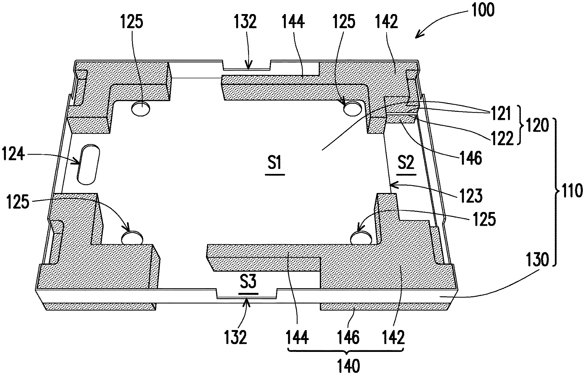
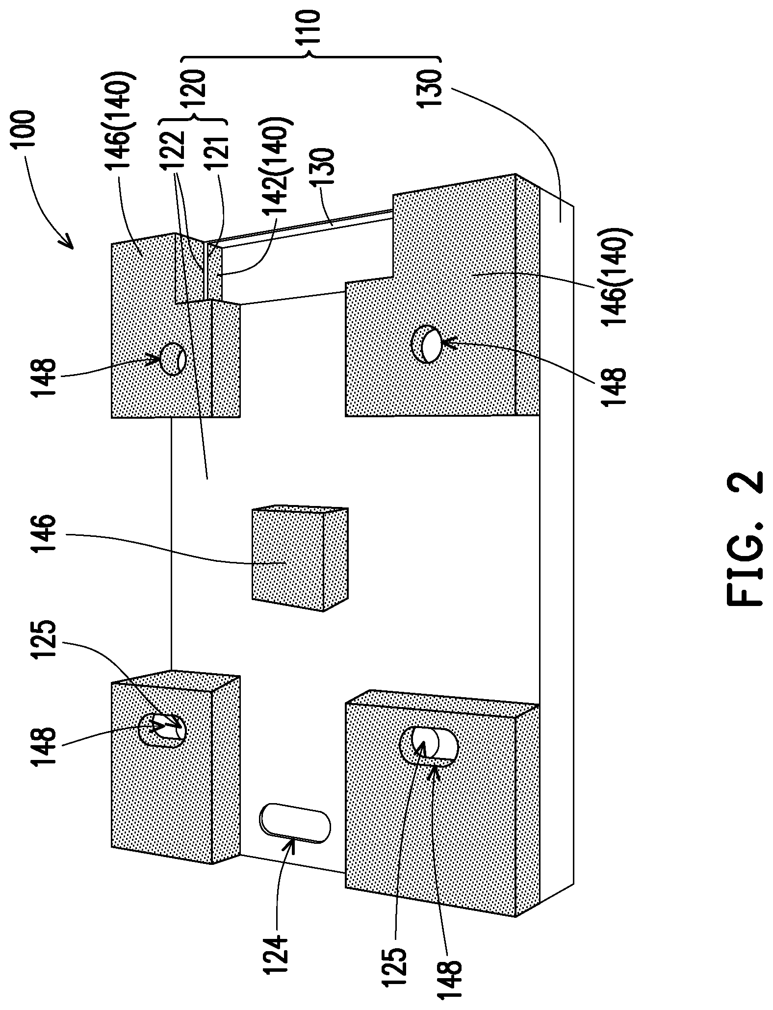
| International Class: | B65D 5/50 20060101 B65D005/50; B65D 81/02 20060101 B65D081/02 |
Foreign Application Data
| Date | Code | Application Number |
|---|---|---|
| Aug 27, 2018 | CN | 201821381333.3 |
Claims
1. A supporting frame, disposed in a packing box and used for packing an object, the supporting frame comprising: a substrate, comprising a bottom plate, wherein the bottom plate has a first surface and a second surface opposite to each other; and a cushion assembly, comprising a first portion and a second portion, the first portion being fixed at four corners of the first surface of the bottom plate, and the second portion being fixed at four corners of the second surface of the bottom plate, wherein at least an inner contour of the first portion of the cushion assembly partially corresponds to an outer contour of the object.
2. The supporting frame of claim 1, wherein the substrate further comprises a plurality of sidewalls surrounding a periphery of the bottom plate, and the sidewalls surround the first portion of the cushion assembly.
3. The supporting frame of claim 2, wherein the sidewalls are equal to the first portion of the cushion assembly in height.
4. The supporting frame of claim 2, wherein the first portion of the cushion assembly comprises an extension section, the extension section extends from one of the first portions located at the four corners of the first surface of the bottom plate, and an accommodation space for an accessory is defined between the extension section and one of the sidewalls.
5. The supporting frame of claim 4, wherein the one of the sidewalls corresponding to the extension section has a first notch, and the first notch is recessed downward from a part of the one of the sidewalls away from the bottom plate, so that a height of the first notch is lower than a height of the extension section.
6. The supporting frame of claim 2, wherein the bottom plate has a second notch recessed inward from a side, and the bottom plate is not connected to the one of the sidewalls at the second notch.
7. The supporting frame of claim 6, wherein the bottom plate has a through handle at a part away from the second notch.
8. The supporting frame of claim 1, wherein the second portion of the cushion assembly is further fixed to a central region of the second surface of the bottom plate.
9. The supporting frame of claim 1, wherein the bottom plate has first through holes, and positions of the first through holes correspond to positions of supporting legs of the object, so as to allow the supporting legs passing through.
10. The supporting frame of claim 9, wherein the second portion of the cushion assembly has second through holes, and positions of the second through holes correspond to the positions of the first through holes of the bottom plate.
11. A packing box, adapted to pack an object, comprising: an outer box; a first supporting frame, disposed in the outer box; and a second supporting frame, wherein the first supporting frame and the second supporting frame are disposed in the outer box in a stack manner, and the object is disposed between the first supporting frame and the second supporting frame, and any one of the first supporting frame and the second supporting frame comprises a substrate and a cushion assembly, wherein the substrate comprises a bottom plate, and the bottom plate has a first surface and a second surface opposite to each other; and the cushion assembly comprises a first portion and a second portion, the first portion is fixed at four corners of the first surface of the bottom plate, and the second portion is fixed at four corners of the second surface of the bottom plate, wherein at least an inner contour of the first portion of the cushion assembly partially corresponds to an outer contour of the object.
12. The packing box of claim 11, further comprising: a surrounding multi-plate reinforcement, configured in the outer box, and surrounding the first supporting frame and the second supporting frame.
13. The packing box of claim 12, wherein the outer box has a U-shaped slit located on a sidewall, and a portion of the sidewall surrounded by the U-shaped slit is folded to form a first opening, and the surrounding multi-plate reinforcement has a second opening corresponding to the first opening.
14. The packing box of claim 11, wherein the substrate of the first supporting frame is the same to the substrate of the second supporting frame, and a configuration position of the cushion assembly of the first supporting frame on the substrate of the first supporting frame is the same to a configuration position of the cushion assembly of the second supporting frame on the substrate of the second supporting frame.
15. The packing box of claim 11, wherein each of the substrates comprises a plurality of sidewalls surrounding a periphery of the bottom plate, and the plurality of sidewalls surround the first portion of the cushion assembly.
16. The packing box of claim 15, wherein the sidewalls are equal to the first portion of the cushion assembly in height.
17. The packing box of claim 15, wherein the first portion of each of the cushion assemblies comprises an extension section, the extension section extends from one of the first portions located at the four corners of the first surface of the bottom plate, and an accommodation space for an accessory is defined between the extension section and the one of the sidewalls.
18. The packing box of claim 17, wherein the one of the sidewalls corresponding to the extension section has a first notch, and the first notch is recessed downward from a part of the one of the sidewalls away from the bottom plate, so that a height of the first notch is lower than a height of the extension section.
19. The packing box of claim 15, wherein each of the bottom plates has a second notch recessed inward from a side, and the bottom plate is not connected to the one of the sidewalls at the second notch.
20. The packing box of claim 19, wherein each of the bottom plates has a through handle at a part away from the second notch.
21. The packing box of claim 11, wherein the second portion of each of the cushion assemblies is further fixed to a central region of the second surface of the bottom plate.
22. The packing box of claim 11, wherein each of the bottom plates has first through holes, and positions of the first through holes correspond to positions of supporting legs of the object, so as to allow the supporting legs passing through.
23. The packing box of claim 22, wherein the second portion of each of the cushion assemblies has second through holes, and positions of the second through holes correspond to the positions of the first through holes of the bottom plate.
Description
CROSS-REFERENCE TO RELATED APPLICATION
[0001] This application claims the priority benefit of China application serial no. 201821381333.3, filed on Aug. 27, 2018. The entirety of the above-mentioned patent application is hereby incorporated by reference herein and made a part of this specification.
BACKGROUND OF THE INVENTION
Field of the Invention
[0002] The invention relates to a supporting frame and a packing box, and particularly relates to a supporting frame and a packing box with the supporting frames stacked for enhanced support and protection.
Description of Related Art
[0003] Generally, when an object such as an electronic device, etc., is packaged, a cushion member made of a low density Expandable Polyethylene (EPE) material is generally disposed on the top or bottom of the object, and the cushion member and the object are altogether placed into a paper carton. Support for such a packing box is mainly provided by the structural strength of the paper carton itself. Moreover, the cushion member in the paper carton is mainly used for reducing the impact to the object that may be caused by a shake or strike.
[0004] However, since the objects may be stacked layer by layer during transportation or storage, the paper cartons located at lower layers need to support weights of the objects on upper layers. During an air transportation, the cushion member is easily contracted due to an air pressure, such that the paper cartons located at the lower layers cannot support the weights of the objects on the upper layer, resulting in paper carton deformation. Moreover, the paper carton itself may also be dampened due to weather factors, resulting in insufficient support and deformation. In addition, the cushion member with a certain thickness may increase a height of the paper carton, such that the number of layers of the paper cartons that may be placed in a container is limited.
[0005] The information disclosed in this BACKGROUND section is only for enhancement of understanding of the BACKGROUND section of the described technology and therefore it may contain information that does not form the prior art that is already known to a person of ordinary skill in the art. Further, the information disclosed in the BACKGROUND section does not mean that one or more problems to be resolved by one or more embodiments of the disclosure were acknowledged by a person of ordinary skill in the art.
SUMMARY OF THE INVENTION
[0006] The invention is directed to a supporting frame, to provide enhanced support and cushioning effect for an object.
[0007] The invention is directed to a packing box, which adopts the above supporting frame to achieve an enhanced support effect and a smaller height.
[0008] Other objects and advantages of the invention may be further illustrated by the technical features broadly embodied and described as follows.
[0009] In order to achieve one or a part or all the objectives or other objectives, an embodiment of the invention provides a supporting frame, which is disposed in a packing box used for packing an object. The supporting frame includes a substrate and a cushion assembly. The substrate includes a bottom plate, where the bottom plate has a first surface and a second surface opposite to each other. The cushion assembly includes a first portion and a second portion, the first portion is fixed at four corners of the first surface of the bottom plate, and the second portion is fixed at four corners of the second surface of the bottom plate, where at least an inner contour of the first portion of the cushion assembly partially corresponds to an outer contour of the object.
[0010] In order to achieve one or a portion of or all of the objects or other objects, an embodiment of the invention provides a packing box adapted to pack an object. The packing box includes an outer box, a first supporting frame and a second supporting frame. The first supporting frame is disposed in the outer box, the first supporting frame and the second supporting frame are disposed in the outer box in a stack manner, and the object is disposed between the first supporting frame and the second supporting frame, and any one of the first supporting frame and the second supporting frame includes a substrate and a cushion assembly. The substrate includes a bottom plate, where the bottom plate has a first surface and a second surface opposite to each other. The cushion assembly includes a first portion and a second portion, the first portion is fixed at four corners of the first surface of the bottom plate, and the second portion is fixed at four corners of the second surface of the bottom plate, where at least an inner contour of the first portion of the cushion assembly partially corresponds to an outer contour of the object.
[0011] Based on the above description, instead of a supporting structure comprised of merely cushiony material, the supporting frame of the invention uses the combination of the substrate and the cushion assembly. Conventionally, the supporting structure comprised of merely cushiony material is required to have a significantly thickness so as to achieve an effective support. In the supporting frame of the invention, the thinner substrate itself provides a good structural strength and thus an effective support. Moreover, a first portion of the cushion assembly is disposed at four corners of the first surface of the bottom plate of the substrate, and at least the inner contour of the first portion of the cushion assembly partially corresponds to the outer contour of the object, so as to fix and protect the object. The second portion of the cushion assembly is fixed at the four corners of the second surface of the bottom plate, so that an impact or a shock may be preferably absorbed effectively. The packing box of the invention has the aforementioned supporting frame, so that a thinner packing box may provide an effective support and cushioning. Therefore, in a limited storage space, the packing boxes of the invention may be stacked in more layers, so as to increase the amount of boxes to be delivered and decrease the cost thereof.
[0012] Other objectives, features and advantages of the present invention will be further understood from the further technological features disclosed by the embodiments of the present invention wherein there are shown and described preferred embodiments of this invention, simply by way of illustration of modes best suited to carry out the invention.
BRIEF DESCRIPTION OF THE DRAWINGS
[0013] The accompanying drawings are included to provide a further understanding of the invention, and are incorporated in and constitute a part of this specification. The drawings illustrate embodiments of the invention and, together with the description, serve to explain the principles of the invention.
[0014] FIG. 1 is a three-dimensional view from a front side of a supporting frame according to an embodiment of the invention.
[0015] FIG. 2 is a three-dimensional view from a back side of the supporting frame of FIG. 1.
[0016] FIG. 3 is a schematic view of a packing box according to an embodiment of the invention.
[0017] FIG. 4 is a schematic view of a surrounding multi-plate reinforcement of the packing box of FIG. 3.
[0018] FIG. 5 is a schematic view of the surrounding multi-plate reinforcement of the packing box of FIG. 3 in an outer box.
[0019] FIG. 6 is a schematic view of the supporting frame of FIG. 1 placed in the outer box of FIG. 5.
[0020] FIG. 7 is a schematic view of another supporting frame placed in the outer box of FIG. 6.
DESCRIPTION OF EMBODIMENTS
[0021] In the following detailed description of the preferred embodiments, reference is made to the accompanying drawings which form a part hereof, and in which are shown by way of illustration specific embodiments in which the invention may be practiced. In this regard, directional terminology, such as "top," "bottom," "front," "back," etc., is used with reference to the orientation of the Figure(s) being described. The components of the present invention can be positioned in a number of different orientations. As such, the directional terminology is used for purposes of illustration and is in no way limiting. On the other hand, the drawings are only schematic and the sizes of components may be exaggerated for clarity. It is to be understood that other embodiments may be utilized and structural changes may be made without departing from the scope of the present invention. Also, it is to be understood that the phraseology and terminology used herein are for the purpose of description and should not be regarded as limiting. The use of "including," "comprising," or "having" and variations thereof herein is meant to encompass the items listed thereafter and equivalents thereof as well as additional items. Unless limited otherwise, the terms "connected," "coupled," and "mounted" and variations thereof herein are used broadly and encompass direct and indirect connections, couplings, and mountings. Similarly, the terms "facing," "faces" and variations thereof herein are used broadly and encompass direct and indirect facing, and "adjacent to" and variations thereof herein are used broadly and encompass directly and indirectly "adjacent to". Therefore, the description of "A" component facing "B" component herein may contain the situations that "A" component directly faces "B" component or one or more additional components are between "A" component and "B" component. Also, the description of "A" component "adjacent to" "B" component herein may contain the situations that "A" component is directly "adjacent to" "B" component or one or more additional components are between "A" component and "B" component. The terms used herein such as "above," "below," "front," "back," "left," and "right" are for the purpose of describing directions in the figures only. Accordingly, the drawings and descriptions will be regarded as illustrative in nature and not as restrictive.
[0022] Generally, objects are stacked into layers during a delivery or storage process, and packing boxes located at lower layers need to support weights of the objects on upper layers. Therefore, the affordability of the packing box at a lower layer for the weight placed thereon is required to satisfy the following equation: the affordability of the packing box at a lower layer for the weight placed thereon (box pressure).gtoreq.a safety coefficient.times.a package weight.times.(the number of stacked layers-1), where the number of the stacked layers.gtoreq.2. The safety coefficient is influenced by factors such as a storage time, a stacking manner, a delivery manner, etc. The safety coefficient may be generally about 4 to 8 in use.
[0023] For example, if the package weight of the object is 50 kg, the safety coefficient is 8, the number of stacked layers is 5, it may be calculated that the weight required to be withstood by the packing box at the lowermost layer is 1600 kg, which means that the packing box at the lowermost layer should be able to withstand a weight of at least 1600 kg. However, it is difficult to meet the above requirements by the paper-made outer box.
[0024] The supporting frame of the embodiment may be disposed in an outer box to enhance an overall structural strength of the packing box, so as to provide an effective support to satisfy a weight bearing demand. Moreover, the supporting frame of the embodiment may be used for wrapping the object to provide good protection and cushioning for the object. A supporting frame 100 is described below.
[0025] FIG. 1 is a three-dimensional view from a front side of a supporting frame according to an embodiment of the invention. FIG. 2 is a three-dimensional view of a back side from the supporting frame of FIG. 1. Referring to FIG. 1 and FIG. 2, in the embodiment, the supporting frame 100 includes a substrate 110 and a cushion assembly 140 disposed on the substrate 110. In the embodiment, a material of the substrate 110 is, for example, corrugated paper which may provide effective support and may have effectively increased strength to support the pressure, such that the overall weight affordability of the packing box 10 may be increased, and the thickness of the supporting frame 100 may be decreased. A material of the cushion assembly 140 is, for example, a low density Expandable Polyethylene (EPE) material which may provide preferable cushioning due to the ability of shape recovery after being compressed. Certainly, the materials of the substrate 110 and the cushion assembly 140 are not limited thereto. In other embodiments, the substrate 110 may also be a plastic member, and the cushion assembly 140 may be rubber, silica gel, a foam material or a spring.
[0026] In the embodiment, the substrate 110 includes a bottom plate 120. The bottom plate 120 has a first surface 121 and a second surface 122 opposite to each other. The cushion assembly 140 includes a first portion 142 and a second portion 146. As shown in FIG. 1, the first portion 142 of the cushion assembly 140 is at least fixed at four corners of the first surface 121 of the bottom plate 120. In the embodiment, an object (not shown, which is, for example, an electronic device such as a projector, etc., though the invention is not limited thereto) is placed on the first surface 121 of the bottom plate 120, and at least a part of the first portion 142 of the cushion assembly 140 surrounds the object to provide protection.
[0027] To be more specific, as shown in FIG. 1, in the embodiment, a main accommodation space S1 is formed and surrounded by a part of the first portion 142 of the cushion assembly 140, and the object may be placed in the main accommodation space S1. At least an inner contour of the first portion 142 of the cushion assembly 140 (such as the part surrounding the main accommodation space S1) may partially correspond to an outer contour of the object, so as to fix the object. Moreover, as shown in FIG. 2, in the embodiment, the second portion 146 of the cushion assembly 140 is at least fixed at four corners of the second surface 122 of the bottom plate 120, so that an impact or a shock may be preferably absorbed effectively.
[0028] Instead of a supporting structure comprised of merely cushiony material, the supporting frame 100 of the embodiment uses the combination the substrate 110 and the cushion assembly 140. Since the substrate 110 itself may provide a good structural strength, good support may be provided under the premise of a smaller thickness.
[0029] Moreover, as shown in FIG. 1, the substrate 110 further includes a plurality of sidewalls 130 surrounding a periphery of the bottom plate 120, and the sidewalls 130 surround the first portion 142 of the cushion assembly 140. In the embodiment, the substrate 110 has four sidewalls 130 connected in pairs, and the four sidewalls 130 respectively extend from four edges of the bottom plate 120 toward a direction protruding out of the first surface 121. In the embodiment, the four sidewalls 130 and the bottom plate 120 commonly construct, for example, a short box structure. The sidewalls 130 are connected to each other and connected to the bottom plate 120, so as to effectively increase an overall structural strength of the substrate 110. In the embodiment, the bottom plate 120 and the sidewalls 130 are, for example, formed integrally. Certainly, the relationship between the bottom plate 120 and the sidewalls 130 of the substrate 110 is not limited thereto.
[0030] Moreover, according to FIG. 1, in the embodiment, the sidewalls 130 are equal to the first portion 142 of the cushion assembly 140 in height. In the above configuration, the sidewalls 130 of the supporting frame 100 and the first portion 142 of the cushion assembly 140 may together provide the support. Certainly, in other embodiments, the first portion 142 of the cushion assembly 140 may also be slightly lower than the sidewalls 130, which is not limited to the invention.
[0031] As shown in FIG. 2, in the embodiment, the second portion 146 of the cushion assembly 140 further includes a portion fixed to a central region of the second surface 122 of the bottom plate 120. Since the second portion 146 located at the central region of the second surface 122 is overlapped with the object, it may provide better cushioning for the object and the object may also be well fixed.
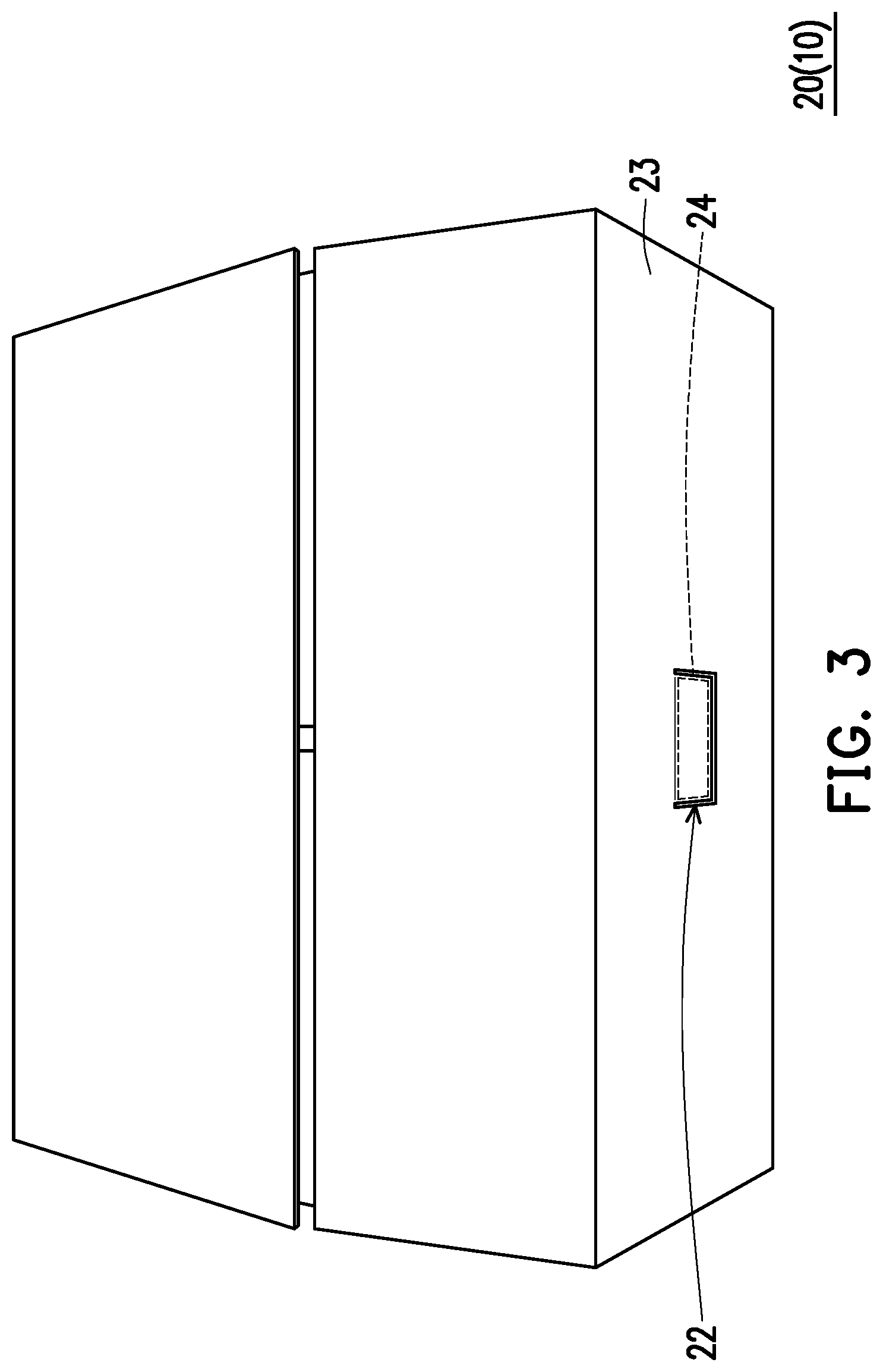
[0032] Moreover, since the packed object is, for example, a projector, and the projector has supporting legs for being used on a table. In the embodiment, as shown in FIG. 1, the bottom plate 120 has first through holes 125, and positions of the first through holes 125 correspond to positions of the supporting legs of the object, such that the supporting legs may pass through and an overall height of the package may be decreased. According to FIG. 2, the second portion 146 of the cushion assembly 140 has second through holes 148, and positions of the second through holes 128 correspond to the first through holes 125 of the bottom plate 120, such that the supporting legs of the object may pass through.
[0033] FIG. 3 is an appearance schematic view of a packing box according to an embodiment of the invention. Referring to FIG. 3, the packing box 10 of the embodiment is used for packing an object (not shown), and used for providing protection for the object, such that the delivery of the object may be easier. For example, the object is an electronic device such as a projector, though the type of the object is not limited thereto. In the embodiment, the packing box 10 includes an outer box 20 and two supporting frames 100 (shown in FIG. 6 and FIG. 7) disposed in the outer box 20. The components configured in the outer box 20 are described in detail below.
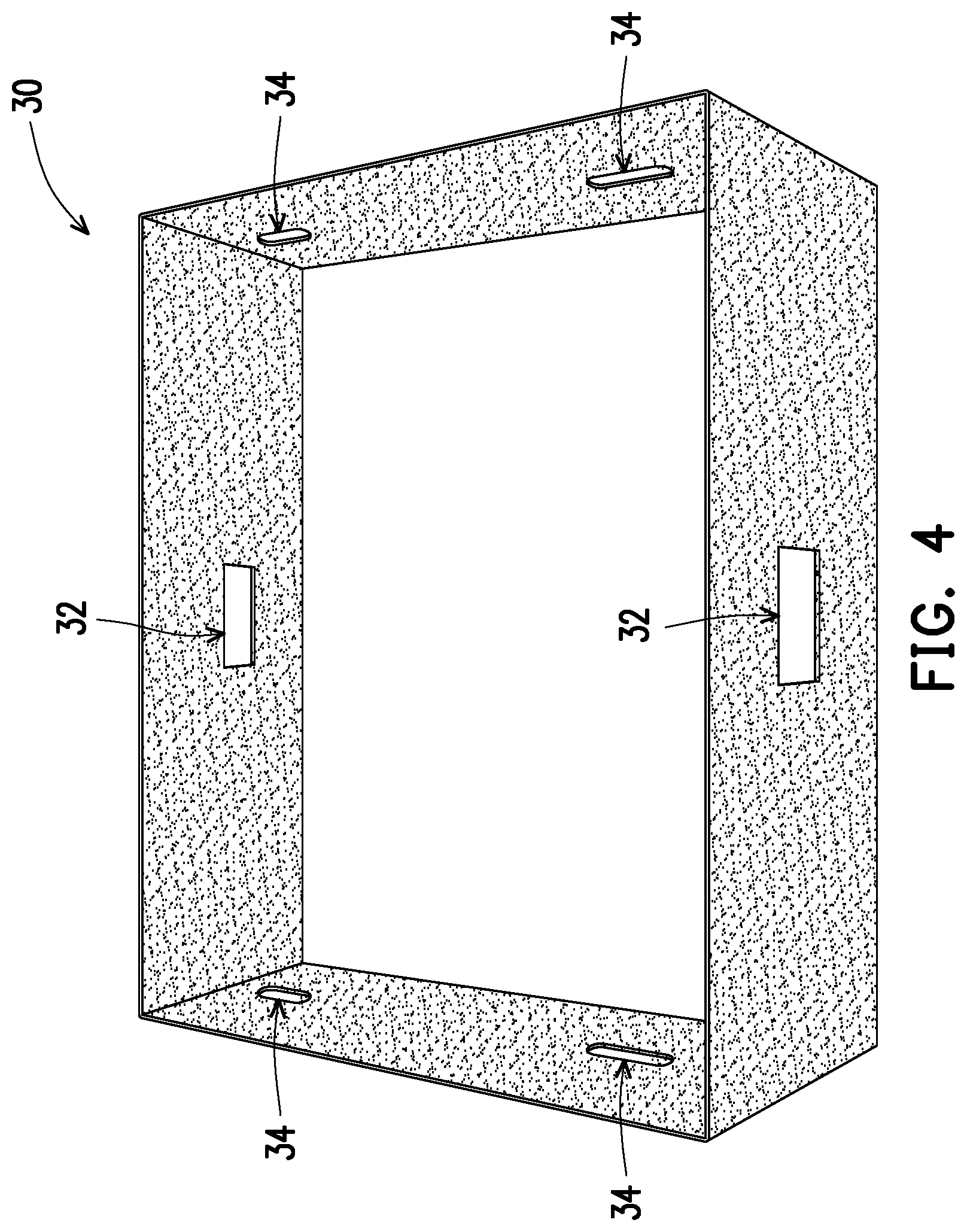
[0034] FIG. 4 is a schematic view of a surrounding multi-plate reinforcement of the packing box of FIG. 3. FIG. 5 is a schematic view of the surrounding multi-plate reinforcement of the packing box of FIG. 3 in the outer box. Referring to FIG. 4 and FIG. 5, in the embodiment, the packing box 10 may optionally include a surrounding multi-plate reinforcement 30, which is configured in the outer box 20 and corresponds to sidewalls 23 of the outer box 20. In the embodiment, a material of the surrounding multi-plate reinforcement 30 is, for example, a corrugated paper, though the material of the surrounding multi-plate reinforcement 30 is not limited thereto. Moreover, in the embodiment, a height of the surrounding multi-plate reinforcement 30 is close to a height of the sidewalls 23 of the packing box 10. The surrounding multi-plate reinforcement 30 is configured to increase a structural strength of the packing box 10, so that the weight affordability of the packing box 10 may be increased. Moreover, in the embodiment, the surrounding multi-plate reinforcement 30 includes a plurality of handle holes 34, and positions of the handle holes 34 correspond to positions of handle holes (not shown) on the outer box 20, which are disposed for the convenience of a user to lift the structure.
[0035] FIG. 6 is a schematic view of the supporting frame of FIG. 1 placed in the outer box of FIG. 5. FIG. 7 is a schematic view of another supporting frame placed in the outer box of FIG. 6. Referring to FIG. 6 and FIG. 7, in the embodiment, the supporting frame 100 in FIG. 6 and the supporting frame 100 in FIG. 7 are both illustrated as examples of the supporting frames 100 shown in FIG. 1 and FIG. 2. Namely, in the embodiment, the two supporting frames 100 are identical. To be more specific, the shape of the substrate 110 of the supporting frame 100 located at a lower position is the same as the shape of the substrate 110 of the supporting frame 100 located at an upper position, and the configuration position of the cushion assembly 140 of the supporting frame 100 located at the lower position on the substrate 110 is the same as the configuration position of the cushion assembly 140 of the supporting frame 100 located at the upper position on the substrate 110. In such configuration, simple manufacture and mistake-prevention (error-prevention) during assembling may be advantageously achieved.
[0036] Certainly, in other embodiments, the supporting frame located at the lower position may be different from the supporting frame located at the upper position. Namely, shapes of the substrates 110 of the two supporting frames 100, or/and configuration positions of the two cushion assemblies 140 on the two substrates 110 may be different. As long as each of the supporting frames 100 includes a substrate 110 and a cushion assembly 140, the first portion 142 of the cushion assembly 140 is at least fixed at the four corners of the first surface 121 of the bottom plate 120, and the second portion 146 of the cushion assembly is at least fixed at the four corners of the second surface 122 of the bottom plate 120, it is considered to be within the scope of the invention.
[0037] In the embodiment, two supporting frames 100 are stacked in the outer box 20, and an object is disposed between the two supporting frames 100. To be specific, in the embodiment, when a worker assembles the packing box 10, the worker may first places one supporting frame 100 in the outer box 20 as that shown in FIG. 6. The second surface 122 of the supporting frame 100 faces a bottom wall 21 of the outer box 20. Namely, the first surface 21 of the supporting frame 100 faces upward. Then, the object is placed in the main accommodation space S1 of the supporting frame 100. Thereafter, as shown in FIG. 7, another supporting frame 100 is placed on the object. As for the supporting frame 100 located at the upper position, the first surface 121 thereof faces the object, and the second surface 122 thereof faces upward.
[0038] Therefore, in the embodiment, when the object is disposed between the two supporting frames 100, two first surfaces 121 of two supporting frames 100 both face the object. The object is located in the two main accommodation spaces S1 of the two supporting frames 100. Moreover, when the two supporting frames 100 are stacked to each other, the supporting frame 100 located at the lower position may support, using the four sidewalls 130 thereof, the four sidewalls 130 of the supporting frame 100 located at the upper position, so that the two supporting frames 100 are firmly stacked in an up and down manner. According to FIG. 7, sidewalls 23 and the surrounding multi-plate reinforcement 30 all surround the two supporting frames 100, to provide a lateral support for the two supporting frames 100.
[0039] It should be noted that, in order to make the packing box 10 to have a margin to add accessories at any time, referring to FIG. 3, in the embodiment, the outer box 20 has a U-shaped slit 22 located on the sidewall 23, and a portion of the sidewall 23 surrounded by the U-shaped slit 22 is adapted to be folded to form a first opening 24. With reference of FIG. 4, in the embodiment, the surrounding multi-plate reinforcement 30 has a second opening 32 corresponding to the first opening 24. Referring back to FIG. 1, in the embodiment, the cushion assembly 140 of the supporting frame 100 further includes an extension section 144 of the first portion 142, which extends from one of the first portions 142 located the four corners. According to FIG. 1, the extension section 144 of the first portion 142 extends from a right corner of FIG. 1 toward a central position, and an accommodation space S3 for an accessory is defined between the extension section 144 and the corresponding sidewall 130. Moreover, in the supporting frame 100 of the embodiment, the sidewall 130 corresponding to the extension section 144 has a first notch 132, and the first notch 132 is recessed downward from a part of the sidewall 130 located away from the bottom plate 120, so that a height of the first notch 132 is lower than a height of the extension section 144. When the two supporting frames 100 are stacked in the outer box 20, where one of the supporting frames 100 is placed facing up and another facing down, two first notches 132 of the two supporting frames 100 may be combined to form one big opening.
[0040] Therefore, in the packing box 10 of the embodiment, in an inward direction, the first opening 24 (shown in FIG. 3) of the sidewall 23 of the outer box 20 sequentially corresponds to the second opening 32 (shown in FIG. 4) of the surrounding multi-plate reinforcement 30, the big opening formed by combining the two first notches 132 (shown in FIG. 1) of the two supporting frames 100 and the two accommodation spaces S3 for accessories of the two supporting frames 100. After a cover of the outer box 20 is closed, through the first opening 24 on the sidewall 23 of the outer box 20, the above connected and corresponding openings and spaces allow the user to place additional accessories into the accommodation space S3 for accessories of the supporting frame 100. Therefore, convenience for adding accessories at any time may be provided.
[0041] For example, different power cord plugs may be used in different countries. In a standard configuration, a commonly used power cord plug is probably provided, and in the packing box 10, a most commonly used power cord plug may be probably placed in an accessory box 12 shown in FIG. 7. However, in case that the packing box 10 is delivered to a different country where a different type of power cord plug is required, a local supplier may add a required power cord plug into the accommodation space S3 for an accessory of the packing box 10 without opening the packing box 10. Certainly, power cord plugs are only examples, and the type of the accessory is not limited to the power cord plugs.
[0042] Moreover, as shown in FIG. 1, in the embodiment, the bottom plate 120 has a second notch 123 recessed inward from a side, the bottom plate 120 is hollow at the second notch 123 without connecting to a corresponding sidewall 130. Referring to FIG. 1 and FIG. 7, in the embodiment, the second notch 123 may serve as an accommodation space S2 for an accessory to accommodate the accessory box 12. In the embodiment, since the second notch 123 is a hollow portion of the bottom plate 120, in the packing box 10, positions of the two second notches 123 of the two supporting frames 100 correspond to each other, so as to provide a space for accommodating the accessory box 12 with a height close to a height of the outer box. Certainly, the type of the second notch 123 is not limited thereto. In the embodiment, the position of the accessory box 120 and the position of the object are in a same plane, and such configuration may reduce the height of the packing box 10, so that more layers of the packing boxes 10 may be stacked under a limited container volume. Moreover, in the embodiment, the bottom plate 120 of the supporting frame 100 has a through handle 124 at a part away from the second notch 123, so as to allow the user to take the supporting frame 100 easily. Therefore, the assembling and disassembling of the supporting frame 100 is easy.
[0043] In summary, instead of a supporting structure comprised of merely cushiony material, the supporting frame of the invention uses the combination of the substrate and the cushion assembly. Conventionally, the supporting structure comprised of merely cushiony material is required to have a significantly thickness so as to achieve an effective support. In the supporting frame of the invention, the thinner substrate itself provides a good structural strength and thus an effective support. Moreover, a first portion of the cushion assembly is disposed at four corners of the first surface of the bottom plate of the substrate, and at least the inner contour of the first portion of the cushion assembly partially corresponds to the outer contour of the object, so as to fix and protect the object. The second portion of the cushion assembly is fixed at the four corners of the second surface of the bottom plate, so that an impact or a shock may be preferably absorbed effectively. The packing box of the invention has the aforementioned supporting frame, so that a thinner packing box may provide an effective support and cushioning. Therefore, in a limited storage space, the packing boxes of the invention may be stacked in more layers, so as to increase the amount of boxes to be delivered and decrease the cost thereof.
[0044] The foregoing description of the preferred embodiments of the disclosure has been presented for purposes of illustration and description. It is not intended to be exhaustive or to limit the disclosure to the precise form or to exemplary embodiments disclosed. Accordingly, the foregoing description should be regarded as illustrative rather than restrictive. Obviously, many modifications and variations will be apparent to practitioners skilled in this art. The embodiments are chosen and described in order to best explain the principles of the disclosure and its best mode practical application, thereby to enable persons skilled in the art to understand the disclosure for various embodiments and with various modifications as are suited to the particular use or implementation contemplated. It is intended that the scope of the disclosure be defined by the claims appended hereto and their equivalents in which all terms are meant in their broadest reasonable sense unless otherwise indicated. Therefore, the term "the disclosure", "the present disclosure" or the like does not necessarily limit the claim scope to a specific embodiment, and the reference to particularly preferred exemplary embodiments of the disclosure does not imply a limitation on the disclosure, and no such limitation is to be inferred. The disclosure is limited only by the spirit and scope of the appended claims. Moreover, these claims may refer to use "first", "second", etc. following with noun or element. Such terms should be understood as a nomenclature and should not be construed as giving the limitation on the number of the elements modified by such nomenclature unless specific number has been given. The abstract of the disclosure is provided to comply with the rules requiring an abstract, which will allow a searcher to quickly ascertain the subject matter of the technical disclosure of any patent issued from this disclosure. It is submitted with the understanding that it will not be used to interpret or limit the scope or meaning of the claims. Any advantages and benefits described may not apply to all embodiments of the disclosure. It should be appreciated that variations may be made in the embodiments described by persons skilled in the art without departing from the scope of the present disclosure as defined by the following claims. Moreover, no element and component in the present disclosure is intended to be dedicated to the public regardless of whether the element or component is explicitly recited in the following claims.
* * * * *
D00000
D00001
D00002
D00003
D00004
D00005
D00006
D00007
XML
uspto.report is an independent third-party trademark research tool that is not affiliated, endorsed, or sponsored by the United States Patent and Trademark Office (USPTO) or any other governmental organization. The information provided by uspto.report is based on publicly available data at the time of writing and is intended for informational purposes only.
While we strive to provide accurate and up-to-date information, we do not guarantee the accuracy, completeness, reliability, or suitability of the information displayed on this site. The use of this site is at your own risk. Any reliance you place on such information is therefore strictly at your own risk.
All official trademark data, including owner information, should be verified by visiting the official USPTO website at www.uspto.gov. This site is not intended to replace professional legal advice and should not be used as a substitute for consulting with a legal professional who is knowledgeable about trademark law.