Pipe End Processing Device
LIU; Jining ; et al.
U.S. patent application number 16/609781 was filed with the patent office on 2020-02-27 for pipe end processing device. The applicant listed for this patent is SANOH INDUSTRIAL CO., LTD.. Invention is credited to Jining LIU, Kazuhiko NAKAZATO.
| Application Number | 20200061902 16/609781 |
| Document ID | / |
| Family ID | 65040475 |
| Filed Date | 2020-02-27 |


| United States Patent Application | 20200061902 |
| Kind Code | A1 |
| LIU; Jining ; et al. | February 27, 2020 |
PIPE END PROCESSING DEVICE
Abstract
A pipe end processing device includes a female die and a male die. The female die has a through hole with one side thereof being radially increased, the through hole having the molding surface for forming the protrusion formed on an inner circumference on the one side of the through hole. The male die includes a metal core passed through the through hole of the female die and configured to be axially moved, and a tubular elastic body fitted on one end part of the metal core and protruding from the one side of the female die. The tubular elastic body is configured to be axially compressed by a movement of the metal core to radially expand by deformation thereby to press the surface to be processed of the pipe against the molding surface of the female die.
| Inventors: | LIU; Jining; (Koga-shi, Ibaraki, JP) ; NAKAZATO; Kazuhiko; (Koga-shi, Ibaraki, JP) | ||||||||||
| Applicant: |
|
||||||||||
|---|---|---|---|---|---|---|---|---|---|---|---|
| Family ID: | 65040475 | ||||||||||
| Appl. No.: | 16/609781 | ||||||||||
| Filed: | April 23, 2018 | ||||||||||
| PCT Filed: | April 23, 2018 | ||||||||||
| PCT NO: | PCT/JP2018/016501 | ||||||||||
| 371 Date: | October 31, 2019 |
| Current U.S. Class: | 1/1 |
| Current CPC Class: | B29L 2023/22 20130101; B21D 41/028 20130101; B29C 57/06 20130101; B21D 37/16 20130101; B29K 2995/0046 20130101 |
| International Class: | B29C 57/06 20060101 B29C057/06 |
Foreign Application Data
| Date | Code | Application Number |
|---|---|---|
| Jul 28, 2017 | JP | 2017-146654 |
Claims
1. A pipe end processing device comprising: a female die having a molding surface for forming a protrusion; and a male die that presses a surface to be processed of a pipe against the molding surface of the female die, the female die having a through hole with one side thereof being radially increased, the through hole having the molding surface for forming the protrusion formed on an inner circumference on the one side of the through hole, and the male die including a metal core passed through the through hole of the female die and configured to be axially moved by a drive device provided on another side of the female die, and a tubular elastic body fitted on one end part of the metal core, the one end part protruding from the one side of the female die, the tubular elastic body being configured to be axially compressed by a movement of the metal core to radially expand by deformation thereby to press the surface to be processed of the pipe against the molding surface of the female die.
2. The pipe end processing device according to claim 1, wherein the metal core is formed into tubular shape to allow a high-temperature fluid to flow into a pipe being processed via the tubular metal core.
3. The pipe end processing device according to claim 1, wherein the tubular elastic body is made of any one of silicone rubber, ethylene rubber, butyl rubber, and chloroprene rubber.
4. The pipe end processing device according to claim 1, further comprising a chuck that clamps an end part of the pipe in addition to the female die and the male die.
Description
TECHNICAL FIELD
[0001] The present invention relates to a pipe end processing device, and more particularly to a pipe end processing device that allows a protrusion such as a flare, bulge, spool and the like to be formed to an end part of a pipe, while also being capable of clamping the end part of the pipe.
BACKGROUND ART
[0002] It is a conventional practice to form protrusions that are called flare, bulge, or spool on end parts of steel or synthetic resin pipes used in various types of tubing such as automotive tubing, for connection with rubber hoses or the like, or with a connection component called "quick connector", in a process of setting up a tubing system. When applied to connection with a rubber hose or the like, the protrusion can ensure and maintain an airtight seal in the connected parts, as well as serves to prevent unwanted disconnection of the hose or the like from the pipe by increasing the friction resistance.
[0003] Hydroforming has been known before as a method of forming protrusions on pipes. In this forming method, the pipe set in the mold is filled with a pressurized liquid while being compressed from both ends by pistons advanced from left and right so as to transform the pipe to conform to the recess formed in the mold (see, for example, PTL 1).
CITATION LIST
Patent Literature
[0004] [PTL 1] Japanese Patent Application Laid-open No. 2002-239645
SUMMARY OF INVENTION
Technical Problem
[0005] The problem with the conventional hydroforming method for forming protrusions described above was that it required a sturdy sealing structure for hermetically containing the high-pressure oil, and since the pipe was axially compressed by applying forces from both ends, the equipment tended to have a complex and bulky structure and the facility cost was high. Another problem was that it was hard to form a protrusion close to an end of the pipe, or to form a protrusion on a pipe that has already been bent, because of the need to clamp both ends of the pipe.
[0006] The present invention was made in view of the problems encountered by the background art described above. An object of the present invention is to provide a pipe end processing device that allows a protrusion to be formed on a pipe by applying a force only from one end, thus allowing a facility cost reduction through size reduction and simplification of the processing device, enables formation of a protrusion close to an end of a pipe or on a pipe that has already been bent, and serves also as a device for clamping an end part of a pipe.
Solution to Problem
[0007] To achieve the object noted above, the present invention provides a pipe end processing device as set forth in the following (1) to (4).
[0008] (1) A pipe end processing device including: a female die having a molding surface for forming a protrusion; and a male die that presses a surface to be processed of a pipe against the molding surface of the female die, the female die having a through hole with one side thereof being radially increased, the through hole having the molding surface for forming the protrusion formed on an inner circumference on the one side of the through hole, and the male die including a metal core passed through the through hole of the female die and configured to be axially moved by a drive device provided on another side of the female die, and a tubular elastic body fitted on one end part of the metal core, the one end part protruding from the one side of the female die, the tubular elastic body being configured to be axially compressed by a movement of the metal core to radially expand by deformation thereby to press the surface to be processed of the pipe against the molding surface of the female die.
[0009] (2) The pipe end processing device set forth in (1) above, wherein the metal core is formed into tubular shape to allow a high-temperature fluid to flow into a pipe being processed via the tubular metal core.
[0010] (3) The pipe end processing device set forth in (1) above, wherein the tubular elastic body is made of any one of silicone rubber, ethylene rubber, butyl rubber, and chloroprene rubber.
[0011] (4) The pipe end processing device set forth in (1) above, further including a chuck that clamps an end part of the pipe in addition to the female die and the male die.
Advantageous Effects of Invention
[0012] The pipe end processing device according to the present invention described above allows a protrusion to be formed on a pipe by applying a force only from one end, thus allowing a facility cost reduction through size reduction and simplification of the processing device, enables formation of a protrusion close to an end of a pipe or on a pipe that has already been bent, and serves also as a device for clamping an end part of a pipe.
BRIEF DESCRIPTION OF DRAWINGS
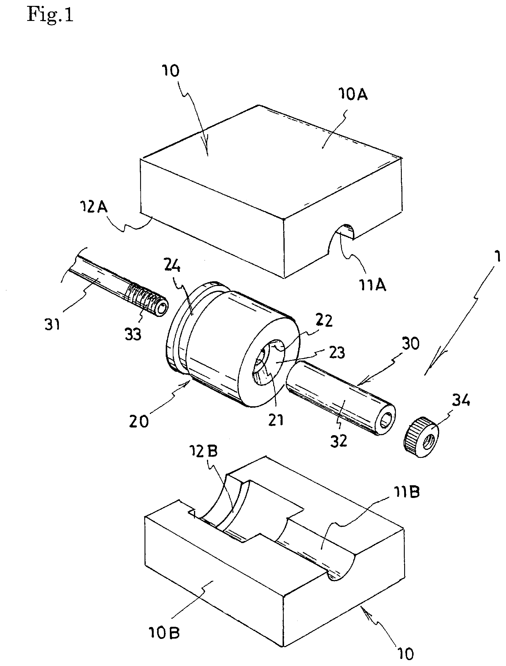
[0013] FIG. 1 is an exploded perspective view illustrating one embodiment of the pipe end processing device according to the present invention.
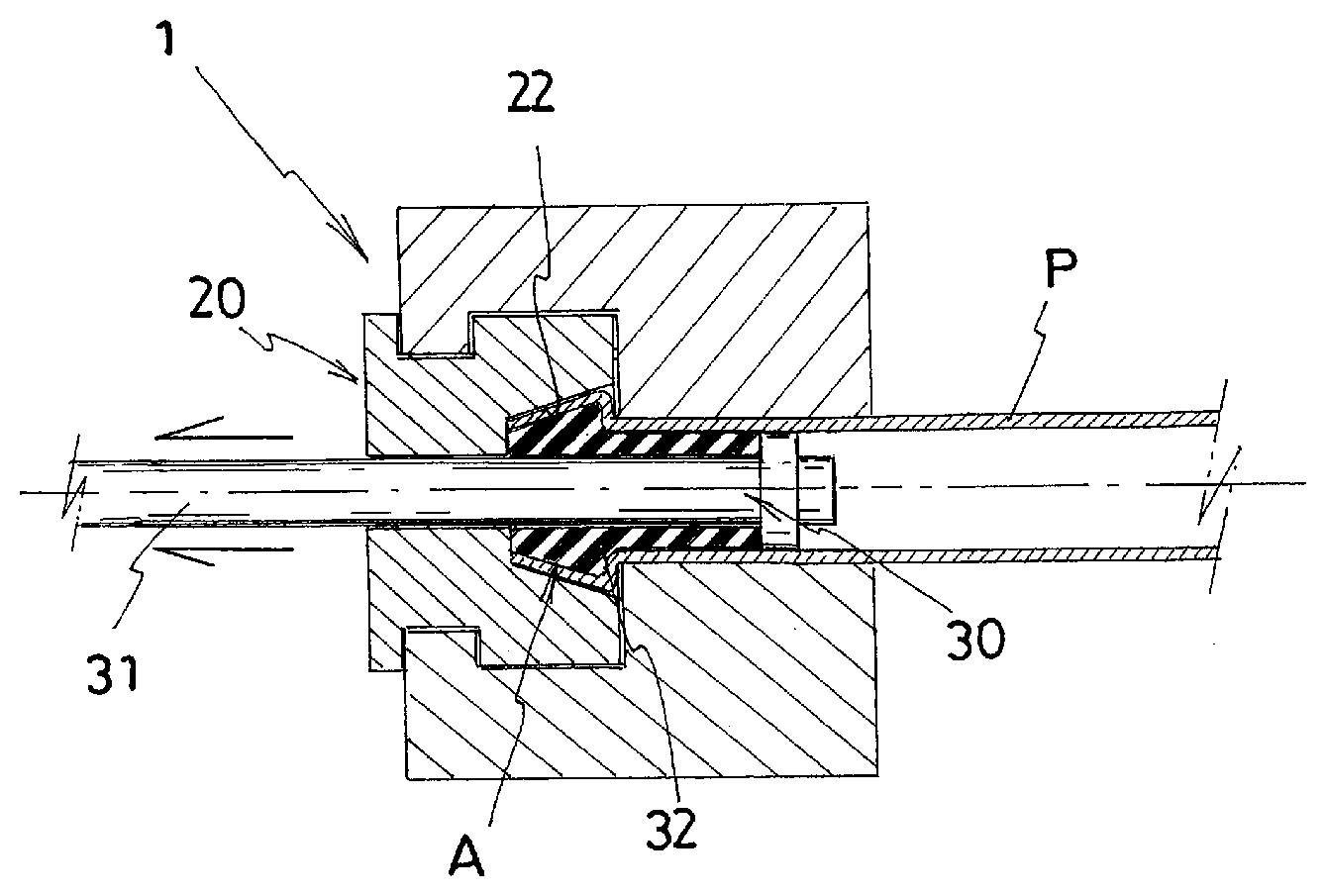
[0014] FIG. 2 is a longitudinal cross-sectional view of the pipe end processing device shown in FIG. 1.
[0015] FIG. 3 is a cross-sectional view illustrating a step of operation of the pipe end processing device shown in FIG. 1, wherein the chuck is opened.
[0016] FIG. 4 is a cross-sectional view illustrating a step of operation of the pipe end processing device shown in FIG. 1, wherein a pipe is attached to the pipe end processing device.
[0017] FIG. 5 is a cross-sectional view illustrating a step of operation of the pipe end processing device shown in FIG. 1, wherein the chuck is closed.
[0018] FIG. 6 is a cross-sectional view illustrating a step of operation of the pipe end processing device shown in FIG. 1, wherein the pipe is processed by the pipe end processing device.
[0019] FIG. 7 is a cross-sectional view illustrating a step of operation of the pipe end processing device shown in FIG. 1, wherein a tubular elastic body is released from stress to stop its deformation.
[0020] FIG. 8 is a cross-sectional view illustrating a step of operation of the pipe end processing device shown in FIG. 1, wherein the chuck is opened.
[0021] FIG. 9 is a cross-sectional view illustrating a step of operation of the pipe end processing device shown in FIG. 1, wherein the pipe is pulled out of the pipe end processing device.
[0022] FIG. 10 is an enlarged cross-sectional view of essential parts of FIG. 6.
DESCRIPTION OF EMBODIMENTS
[0023] Hereinafter, an embodiment of the pipe end processing device according to the present invention will be described in detail with reference to the drawings.
[0024] The drawings illustrate one embodiment of the pipe end processing device according to the present invention, wherein the illustrated pipe end processing device 1 includes a chuck 10, a female die 20, and a male die 30.
[0025] The chuck 10 is made up of a pair of combined chuck splits 10A and 10B so that it can be split into upper half and lower half. The chuck splits 10A and 10B are respectively formed with grooves 11A and 11B for holding a pipe P and female die receiving grooves 12A and 12B in which the female die 20 fits. The chuck splits 10A and 10B that form the chuck 10 are configured to move up and down respectively by a drive device (not shown) to clamp or release an end part of a pipe P.
[0026] The female die 20 is formed in a columnar shape, with a through hole 21 in the axial center. The through hole 21 has a radially increasing inner circumferential surface on one side where there is a molding surface 22 that imparts a form to a pipe P. In the illustrated embodiment, this molding surface 22 is a cavity 23 formed by an annular recess for forming an annular protrusion A called bulge to an end part of the pipe P. The female die 20 also has a position restricting groove 24 on an outer circumferential surface. The female die 20 should preferably be made of a material that has rigidity and good heat conductivity, for example a metal having heat-resistant and pressure-resistant characteristics such as aluminum, copper, SUS, brass, etc.
[0027] The male die 30 is made up of a metal core 31 inserted into the through hole 21 in the female die 20 described above, and a tubular elastic body 32 fitted on this metal core 31. In the illustrated embodiment, external threads 33 are formed at the distal end of the metal core 31, and with a nut 34 that doubles as a pressing plate for pressing the tubular elastic body 32 screwed on the external threads 33, the tubular elastic body 32 fitted on the metal core 31 is supported thereon.
[0028] The metal core 31 is configured to move along the axial direction by a drive device (not shown) provided on the other side of the female die 20 (left side in the drawing). The tubular elastic body 32 fitted on the metal core 31 is axially compressed by the movement of the metal core 31 to radially expand by deformation, thereby pressing a surface to be processed of the pipe P against the molding surface 22 of the female die 20 and causing a plastic deformation of the pipe P. The metal core 31 is formed into tubular shape so that it allows a fluid to pass through therein, and configured to allow a high-temperature fluid Z to be introduced into the attached pipe P via the tubular metal core 31.
[0029] The tubular elastic body 32 is formed as a tubular member having an outside diameter that is equal to or slightly smaller than the inside diameter of the pipe P to be processed, and an inside diameter that is equal to or slightly larger than the outside diameter of the metal core 31. The tubular elastic body 32 should preferably be formed of silicone rubber, ethylene rubber, butyl rubber, or chloroprene rubber, from the viewpoints of elasticity, and shock-resistant and heat-resistant characteristics. The tubular elastic body 32 need not necessarily be made of a single material and may have a double-layer structure using different materials for inner layer and outer layer.
[0030] The pipe end processing device 1 according to the present invention configured as described above is operated as follows wherein it processes an end part of the pipe P as well as clamps the end part.
[0031] First, as shown in FIG. 3, the chuck splits 10A and 10B that form the chuck 10 are moved up and down respectively by the drive device (not shown) to open the chuck 10 so that there is formed a space for inserting a pipe P. Then, the pipe P is moved by a robot hand or the like (not shown), and as shown in FIG. 4, an end part of the pipe P is attached to the tubular elastic body 32 of the male die 30 and inserted into the cavity 23 inside the molding surface 22 of the female die 20.
[0032] Next, as shown in FIG. 5, the chuck 10 is closed by the drive device (not shown) to clamp the end part of the pipe P with the chuck splits 10A and 10B. In this state, as shown in FIG. 6, the metal core 31 is pulled outward (leftward in the drawing) by the drive device (not shown) to axially compress the tubular elastic body 32 fitted on the metal core 31 so that the elastic body deforms to radially expand and presses the surface to be processed of the pipe P against the molding surface 22 of the female die 20, whereby an annular protrusion A called bulge is formed by the molding surface 22 on the end part of the pipe P. At this time, as shown in FIG. 10 to a larger scale, a high-temperature fluid (e.g., heated steam at a temperature of 110.degree. C. to 170.degree. C. and a pressure of 0.1 to 0.6 MPa) Z can be introduced into the pipe P via the tubular metal core 31. This causes thermal expansion of the tubular elastic body 32 so that the pressing force is increased, enabling more precise processing of the pipe P and enhancing the clamping force. Also, the heating of the entire pipe P allows certain processing such as bending to be performed to the pipe P.
[0033] When the intended processing operation to the pipe P is finished, the grip by the pipe end processing device 1 according to the present invention is loosened and the pipe P is pulled out. To release the pipe P from the hold, first, the pulling of the metal core 31 by the drive device (not shown) is stopped so that the tubular elastic body 32 that has deformed and expanded returns to its original state by its elasticity, as shown in FIG. 7. The supply of a high-temperature fluid Z, if any, into the pipe P through the metal core 31 is stopped. Next, the chuck 10 is opened by the drive device (not shown) to release the pipe P from the grip by the chuck splits 10A and 10B as shown in FIG. 8. Next, the pipe P is pulled out of the pipe end processing device 1 by the robot hand or the like (not shown) as shown in FIG. 9.
[0034] The annular protrusion A called bulge formed to the end part of the pipe P as described above is formed by the molding surface 22 of the female die 20 that has a uniform surface without joints, so that a very smooth annular protrusion A without irregularities such as burrs can be formed, and the protrusion A, which does not require any secondary processing such as polishing, when applied to connection with a rubber hose or the like, can ensure and maintain an airtight seal in the connected parts, as well as serves to prevent unwanted disconnection of the hose or the like from the pipe P by increasing the friction resistance.
[0035] The pipe end processing device 1 according to the present invention described above allows the protrusion A to be formed on the pipe P by applying a force only from one end, i.e., allows a facility cost reduction through size reduction and simplification of the processing device. Moreover, it enables formation of a protrusion A close to an end of a pipe P or on a pipe P that has already been bent, and since it serves also as a device for clamping an end part of a pipe P, the device can be used also as a chuck device when bending or otherwise processing the pipe P.
[0036] While one embodiment of the chuck device according to the present invention has been described, it goes without saying that the technical scope of the present invention is not limited to the embodiment described above. It will be obvious to a person skilled in the art that various modifications and improvements can be made to the embodiment described above, and as will be clear from the wordings of the claims, the forms with these modifications and improvements can also be included in the technical scope of the present invention.
Industrial Applicability
[0037] The pipe end processing device according to the present invention described above allows a facility cost reduction through size reduction and simplification, enables formation of a protrusion close to an end of a pipe or on a pipe that has already been bent, and also serves as a device for clamping an end part of a pipe, so that it can be suitably used as a device for processing an end part of a steel or synthetic resin pipe used in various types of tubing such as automotive tubing, or as a chuck device for clamping the end part when bending or otherwise processing the pipe.
REFERENCE SIGNS LIST
[0038] 1 Pipe end processing device
[0039] 10 Chuck
[0040] 10A, 10B Chuck split
[0041] 11A, 11B Groove for holding pipe
[0042] 12A, 12B Female die receiving groove
[0043] 20 Female die
[0044] 21 Through hole
[0045] 22 Molding surface
[0046] 23 Cavity
[0047] 30 Male die
[0048] 31 Metal core
[0049] 32 Tubular elastic body
[0050] 33 External threads
[0051] 34 Nut (pressing plate)
[0052] P Pipe
[0053] A Annular protrusion (bulge)
[0054] Z High-temperature fluid (heated steam)
* * * * *
D00000
D00001
D00002
D00003
D00004
D00005
D00006
D00007
XML
uspto.report is an independent third-party trademark research tool that is not affiliated, endorsed, or sponsored by the United States Patent and Trademark Office (USPTO) or any other governmental organization. The information provided by uspto.report is based on publicly available data at the time of writing and is intended for informational purposes only.
While we strive to provide accurate and up-to-date information, we do not guarantee the accuracy, completeness, reliability, or suitability of the information displayed on this site. The use of this site is at your own risk. Any reliance you place on such information is therefore strictly at your own risk.
All official trademark data, including owner information, should be verified by visiting the official USPTO website at www.uspto.gov. This site is not intended to replace professional legal advice and should not be used as a substitute for consulting with a legal professional who is knowledgeable about trademark law.