Apparatus And Method For Applying Ceramic Foam Filters For The Removal Of Unwanted Inclusions From Metal Melts
TUNDAL; Ulf Hakon ; et al.
U.S. patent application number 16/611648 was filed with the patent office on 2020-02-27 for apparatus and method for applying ceramic foam filters for the removal of unwanted inclusions from metal melts. This patent application is currently assigned to NORSK HYDRO ASA. The applicant listed for this patent is NORSK HYDRO ASA. Invention is credited to John Olav FAGERLIE, Terje HAUGEN, Idar Kjetil STEEN, Ulf Hakon TUNDAL.
| Application Number | 20200061697 16/611648 |
| Document ID | / |
| Family ID | 62167336 |
| Filed Date | 2020-02-27 |


| United States Patent Application | 20200061697 |
| Kind Code | A1 |
| TUNDAL; Ulf Hakon ; et al. | February 27, 2020 |
APPARATUS AND METHOD FOR APPLYING CERAMIC FOAM FILTERS FOR THE REMOVAL OF UNWANTED INCLUSIONS FROM METAL MELTS
Abstract
Apparatus and a method for filtering molten metal, in particular aluminium, including a container (1) with a removable lid (20) provided on top of the container to keep the container sealed (air tight) during operation, the container (1) being provided with an inlet chamber (2) having an inlet opening (5) receiving metal from a metal supply launder (10) and outlet chamber (3) with outlet opening (6) connected to a launder segment (10'). The container further being provided with partition wall (8) between the inlet chamber (2) and outlet chamber (3) and with ceramic foam filter (17) mounted in the outlet chamber. The inlet chamber (2) and outlet chamber (3) are provided side by side within the container (1) and being split by the partition wall (8) extending from the bottom of the container and upwardly to a preset level of the container interior height. The container (1) is connected in parallel with the metal supply launder (10) via stubs (5', 6') that communicates with the inlet (5) and outlet (6) openings respectively, the launder (10) being provided with a dam (14) or valve device downstream the outlet (6) of the container (1) and another dam or valve device (13) between the said launder stubs (5' and 6'). Inside the container (1) there is further arranged a second outlet chamber (4) with a filter (17') that when in use, communicates with the first outlet chamber (3) via a space above a partition wall (8) extending from the bottom of the container and upwardly to a preset level of the container interior height, where the second outlet chamber (4) has one outlet (7) provided by a stub (7') connected to a launder segment (10'') being in connection with metal supply launder (10). The second outlet chamber (4) is used for increasing the filter capacity when producing metal with a high cleanliness.
| Inventors: | TUNDAL; Ulf Hakon; (Sunndalsora, NO) ; STEEN; Idar Kjetil; (Sunndalsora, NO) ; FAGERLIE; John Olav; (Sunndalsora, NO) ; HAUGEN; Terje; (Surnadal, NO) | ||||||||||
| Applicant: |
|
||||||||||
|---|---|---|---|---|---|---|---|---|---|---|---|
| Assignee: | NORSK HYDRO ASA Oslo NO |
||||||||||
| Family ID: | 62167336 | ||||||||||
| Appl. No.: | 16/611648 | ||||||||||
| Filed: | May 15, 2018 | ||||||||||
| PCT Filed: | May 15, 2018 | ||||||||||
| PCT NO: | PCT/EP2018/062453 | ||||||||||
| 371 Date: | November 7, 2019 |
| Current U.S. Class: | 1/1 |
| Current CPC Class: | C22B 21/066 20130101; C22B 9/023 20130101; B22D 11/119 20130101; C22B 21/0084 20130101; B22D 43/004 20130101 |
| International Class: | B22D 11/119 20060101 B22D011/119; C22B 21/06 20060101 C22B021/06; C22B 21/00 20060101 C22B021/00; C22B 9/02 20060101 C22B009/02; B22D 43/00 20060101 B22D043/00 |
Foreign Application Data
| Date | Code | Application Number |
|---|---|---|
| May 31, 2017 | NO | 20170897 |
Claims
1. Apparatus for filtering molten metal, in particular aluminium, including a container (1) with an outer shell or casing of metal and an inner thermally insulated interior cladding or wall construction made of heat resistant insulation and refractory material, a removable lid (20) provided on top of the container to keep the container sealed (air tight) during operation, the container (1) being provided with an inlet chamber (2) having an inlet opening (5) receiving metal from a metal supply launder (10) and outlet chamber (3) with outlet opening (6) connected to a launder segment (10'), the container further being provided with partition wall (8) between the inlet chamber (2) and outlet chamber (3) and with ceramic foam filter (17) mounted in the outlet chamber, the inlet chamber (2) and outlet chamber (3) are provided side by side within the container (1) and being split by the partition wall (8) extending from the bottom of the container and upwardly to a preset level of the container interior height, whereby the container (1) is connected in parallel with the metal supply launder (10) via stubs (5', 6') that communicates with the inlet (5) and outlet (6) openings respectively, the launder (10) being provided with a dam (14) or valve device downstream the outlet (6) of the container (1) and another dam or valve device (13) between the said launder stubs (5' and 6'), characterised in that inside the container (1) there is further arranged a second outlet chamber (4) with a filter (17') that when in use, communicates with the first outlet chamber (3) via a space above a partition wall (8) extending from the bottom of the container and upwardly to a preset level of the container interior height, where the second outlet chamber (4) has one outlet (7) provided by a stub (7') connected to a launder segment (10'') being in connection with metal supply launder (10).
2. Apparatus according to claim 1, characterised in that the second outlet chamber (4), when not in use can be separated from the first outlet chamber (3) by a segment (21) that is arranged at the top of the partition wall 9 to avoid that metal flows into the said second outlet chamber (4) and that the outlet (7) of said chamber can be closed by an air tight sealing (16).
3. Apparatus according to claim 2, characterised in that the launder segment 10'' can be removed and that the launder segment (10') can be sealed by a dam (15).
4. Apparatus according to claim 2, characterised in that the filter (17') can be removed from said second chamber (4).
5. Apparatus according to claim 1, characterised in that the grade of the filters (17, 17') when both chambers are operated can be 60-80 ppi.
6. Apparatus according to claim 1, characterised in that the grade of the filter (17) when only the first chamber is operated can be 30-50 ppi.
7. A method for filtering molten metal, in particular aluminium, including a container (1) with an outer shell or casing of metal and an inner thermally insulated interior cladding or wall construction made of heat resistant insulation and refractory material, a removable lid (20) provided on top of the container to keep the container sealed (air tight) during operation, the container (1) being provided with an inlet chamber (2) having an inlet opening (5) receiving metal from a metal supply launder (10) and outlet chamber (3) with outlet opening (6) connected to a launder segment (10'), the container further being provided with partition wall (8) between the inlet chamber (2) and outlet chamber (3) and with ceramic foam filter (17) mounted in the outlet chamber, the inlet chamber (2) and outlet chamber (3) are provided side by side within the container (1) and being split by the partition wall (8) extending from the bottom of the container and upwardly to a preset level of the container interior height, whereby the container (1) is connected in parallel with the metal supply launder (10) via stubs (5', 6') that communicates with the inlet (5) and outlet (6) openings respectively, the launder (10) being provided with a dam (14) or valve device downstream the outlet (6) of the container (1) and another dam or valve device (13) between the said launder stubs (5' and 6'), characterised in that inside the container (1) there is arranged a second outlet chamber (4) with a filter (17') that is used for increasing the filter capacity when producing metal with a high cleanliness where said second outlet chamber (4) communicates with the first outlet chamber (3) via a space above a partition wall (8) extending from the bottom of the container and upwardly to a preset level of the container interior height, where the second outlet chamber (4) has one outlet (7) provided by a stub (7') connected to a launder segment (10'') being in connection with metal supply launder (10).
8. Method according to claim 7, characterised in that the filters (17, 17') are primed as follows; as the first metal is released from the furnace the dam (14) is closed whereas the dam (13) between the inlet (5) and outlet openings (6, 7) is open, as soon as the metal level is above the inlet and the outlet openings (5, 6 and 7), air inside the box (1) is evacuated whereby the metal in the inlet (2) and outlet (3, 4) chambers is lifted, the metal will stop against the bottom of the filters (17, 17') in the outlet chambers because there is a resistance for the metal to enter into a filter with small pores, in the inlet chamber (2) the metal will continue to rise as the under-pressure increases, as the height difference between the bottom of the filters (17, 17') and the metal inside the inlet chamber (2) has reached a certain level, the pressure on the bottom of the filters will be high enough to prime the filters, i.e. metal starts to penetrate into the filters.
9. Method according to claim 7, characterised in that the grade of the filters (17, 17') when both chambers are operated can be 60-80 ppi.
Description
[0001] The present invention concerns an apparatus and a method for applying ceramic foam filters for the removal of unwanted inclusions from metal melts by filtration.
[0002] It is generally known to remove small inclusions from molten metal such as molten aluminium by filtration. A typical material used for such filters is porous ceramic, commonly referred to as CFF (Ceramic Foam Filters). These CF (Ceramic Foam) filters are not easily wetted by the molten metal and since such materials have relatively fine pores, considerable difficulties are encountered in initiating the flow of metal through the filter (priming the filter). It is therefore generally known to use deep filter boxes to generate sufficient metal head by gravitation to force the metal through the filter.
[0003] WO2016/126165A1 (of the present applicant), describes an apparatus and a method that operates in a different way than CFF boxes as mentioned above. By lifting the metal with the use of underpressure in the filter box it is possible to avoid drainage of metal after the cast has been finished. In addition, the new CF filter concept provides a different and a very good priming of the filter, as the metal flow through the filter during priming is in the opposite direction as that during ordinary operation.
[0004] The present invention is based on the same principles for priming the filter as WO2016/126165A1 filter box but relates to further improvements by making the CFF box flexible. It is built as a double CFF box but it can also be operated as a single CFF box (or built as a triple box and also operated as a double box)
[0005] The invention is characterized by the features as defined in the independent claim 1. Dependent claims x-y define preferred embodiments of the invention.
[0006] The invention will be further described in the following with reference to the drawings where:
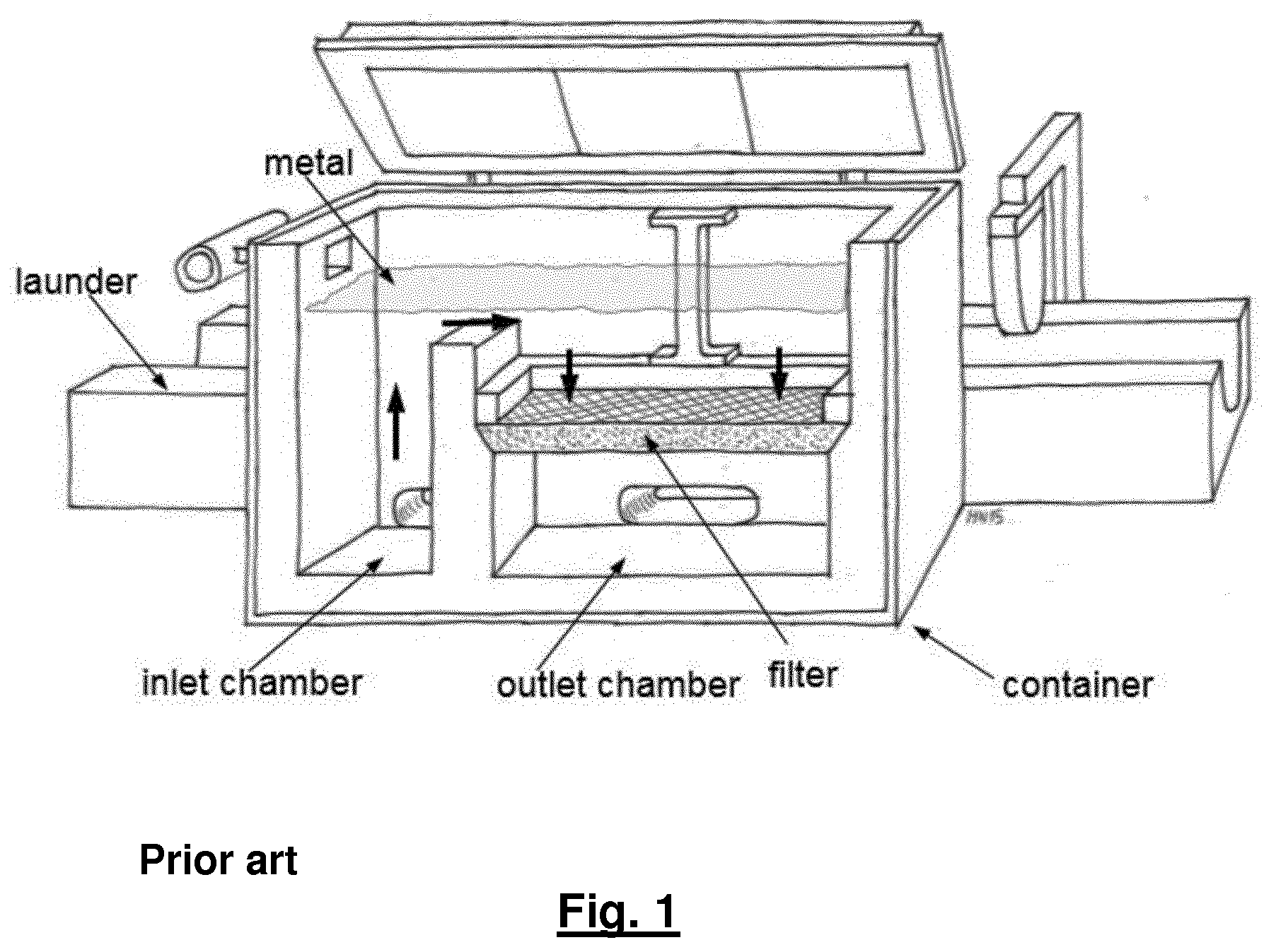
[0007] FIG. 1 shows in perspective view a cross section of a CF filter device or apparatus according to the invention described in WO2016/126165A1,
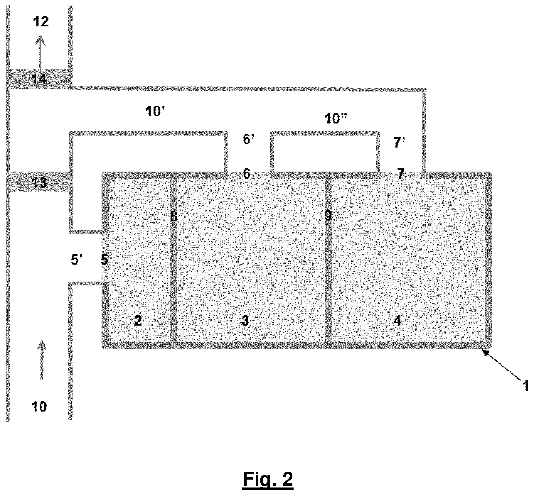
[0008] FIG. 2 shows a top view of a double CF filter apparatus, with one inlet chamber 2 and two outlet cambers 3, 4 connected to a launder system for the supply of metal to and from the filter apparatus,
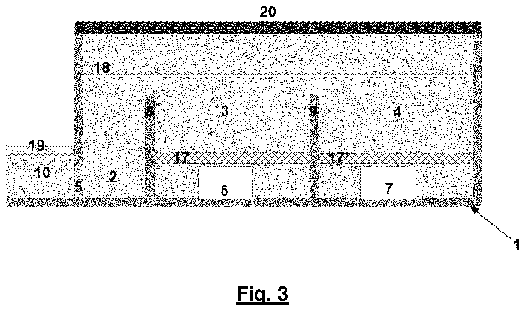
[0009] FIG. 3 shows a cross-sectional view of the double CF filter apparatus shown in FIG. 2 with the metal level 19 in the launder outside the box and the metal level 18 inside the box indicated,
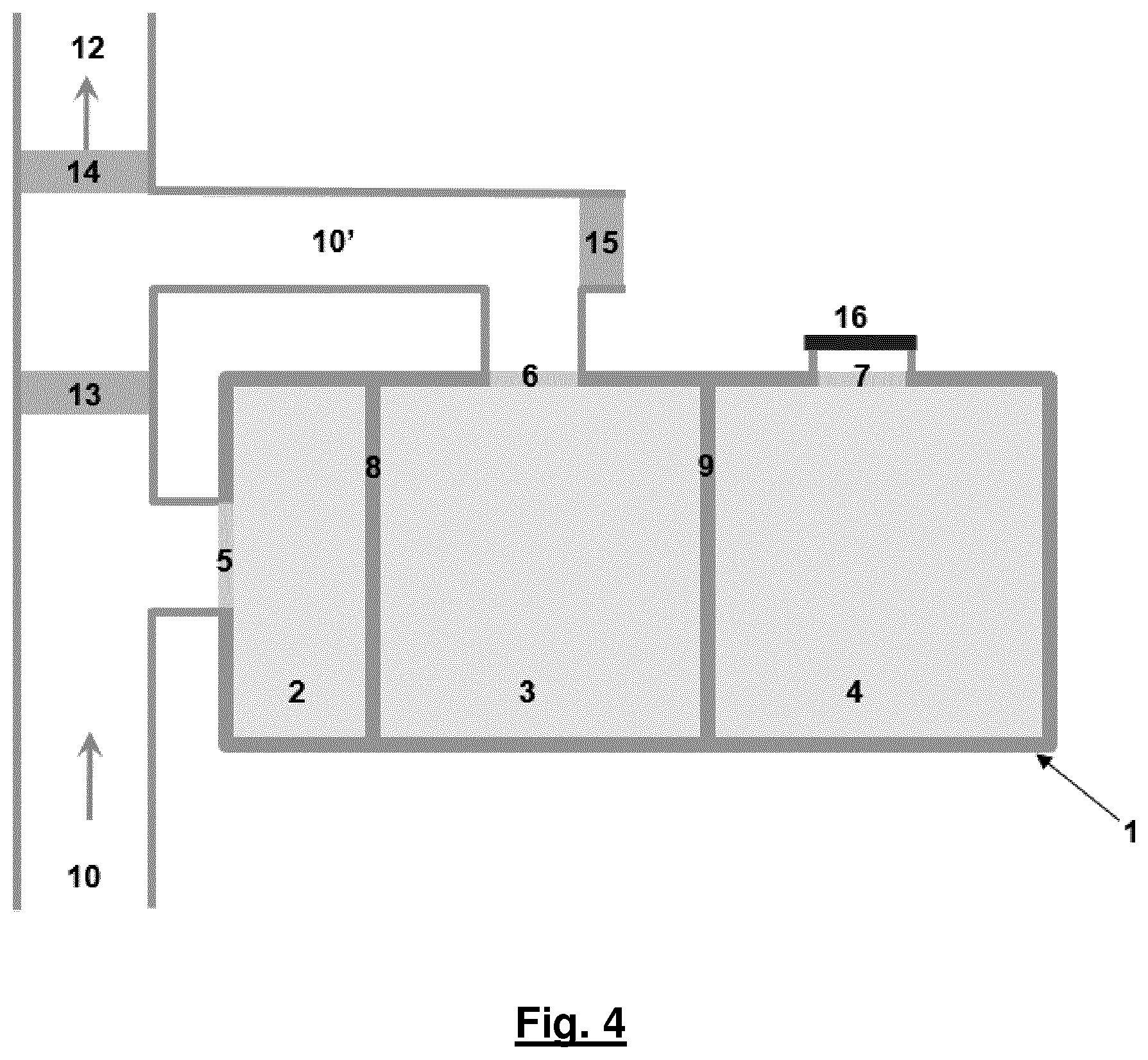
[0010] FIG. 4. shows a top view of a the same double CF filter apparatus as in FIG. 2, but with the launder segment from outlet chamber 4 removed and the outlet opening 7 closed off with an air tight sealing 16. The open launder segment is sealed with a dam 15,
[0011] FIG. 5 shows a cross-sectional view of the double CF filter apparatus as shown in FIG. 4 with the outlet opening 7 closed off and the height of the partition wall between the outlet chambers increased with a removable segment of a refractory material 21.
[0012] FIG. 1 shows the prior art CF filter apparatus according to the WO2016/126165A1 and includes a container or box construction with an outer shell or casing of metal and an inner thermally insulated interior cladding or wall construction made of heat resistant insulation and refractory material. A removable lid is provided on the top of the container to keep the container sealed (air tight) during operation. The container has an inlet opening receiving metal from a metal supply launder, and an outlet chamber with an outlet opening where the CF filter is mounted the outlet chamber.
[0013] The inlet chamber and outlet chamber are provided side by side within the container, being split by a partition wall extending from the bottom of the container and upwardly, to a preset level of the container interior height. The container is connected in parallel with a metal supply launder via transversal metal launder stubs respectively provided between the inlet and outlet openings of the container and the metal supply launder. To control the metal flow in the metal supply launder, two dams are provided in the launder, one dam after the outlet of the container and the other dam in the launder between the inlet and outlet openings.
[0014] This apparatus is operated in the following way: When metal is released from the furnace, the dam downstream the container is closed whereas the dam between the inlet and outlet openings is open. As soon as the metal level in the launder is above the inlet and the outlet openings, an ejector starts to evacuate the air inside the container lifting the metal upwards in the inlet and outlet chambers. The metal will stop against the bottom of the filter in the outlet chamber because there is a resistance for the metal to enter into a filter with small pores. In the inlet chamber the metal level will continue to rise as the under-pressure increases. When the height difference between the bottom of the filter and the metal inside the inlet chamber has reached a certain level, the pressure on the bottom of the filter will be high enough to prime the filter. The maximum pressure for priming that can be obtained with this solution will be the height difference between the bottom of the filter and the top of the partition wall. To prevent that the filter floats up when the pressure against the bottom of the filter increases, there is a clamping device mounted to hold down the filter. When the priming operation is finished the under-pressure is reduced and correspondingly the metal level inside the box is increased to above the partition wall as indicated in the Figure. At this point the dam between the inlet and the outlet openings will be closed and the dam downstream the container will be opened. Then the metal is forced to go through the inlet opening, above the partition wall, through the filter and out through the outlet opening. When the cast is close to being finished the metal level inside the container is gradually lowered by reducing the under-pressure and the metal eventually released into the launders.
[0015] FIG. 2 shows a top view of a CF filter apparatus according to the present invention, with one inlet chamber 2 and an inlet opening 5 connected to the main launder 10 coming from the furnace, two outlet chambers 3, 4 and two outlet openings 6, 7 connected to launder 10 via launder segments 10', 10''. The three different chambers are separated by two partition walls 8, 9. Two dams 13, 14 are controlling the metal flow in the start-up phase and in the operating phase. The launder 12 leads the metal from the container or filter box 1 towards the casting pit.
[0016] FIG. 3 shows a cross-sectional view of the same filter apparatus as shown in FIG. 2. A filter 17, 17' is mounted in each of the outlet chambers 3, 4. The metal levels outside the inlet opening 5 and inside the box 1 during operation are indicated by 19 and 18 respectively. This apparatus is operated similar to the single CFF box shown in FIG. 1: When the first metal is released from the furnace the dam 14 is closed whereas the dam 13 between the inlet 5 and outlet openings 6, 7 is open. As soon as the metal level is above the inlet and the outlet openings 5, 6 and 7, an ejector (not shown) starts to evacuate the air inside the box 1 lifting the metal in the inlet 2 and outlet 3, 4 chambers. The metal will stop against the bottom of the filters 17, 17' in the outlet chambers because there is a resistance for the metal to enter into a filter with small pores. In the inlet chamber 2 the metal will continue to rise as the under-pressure increases. When the height difference between the bottom of the filters 17, 17' and the metal inside the inlet chamber 2 has reached a certain level, the pressure on the bottom of the filters will be high enough to prime the filters, i.e. metal starts to penetrate into the filters. If one filter primes before the other filter, the metal level in the chamber where the priming has completed will rise to the same level as the metal level in the inlet chamber. Upon further reduction in the under-pressure the second filter will also prime.
[0017] When the priming operation is finished the metal level 18 inside the box is increased to above the partition walls 8, 9 as indicated in FIG. 3. At this point the dam 13 between the inlet and the outlet openings is closed and the dam 14 is opened. Then the metal is forced to go through the inlet opening 5, above the partition walls 8, 9, through the filters 17, 17' and out through the outlet openings 6, 7. When the cast is close to being finished the metal level inside the box is gradually lowered by reducing the underpressure and the metal eventually released into the launder 10.
[0018] FIG. 4 shows a top view of a the same double CF filter apparatus as in FIGS. 2 and 3, but with the launder segment 10'' from outlet chamber 4 taken away and the outlet 7 closed off with an air tight sealing 16. The open launder segment 10' is sealed with a dam 15.
[0019] FIG. 5 shows a side view of the same apparatus as shown in FIG. 4 with the outlet opening 7 closed off and the height of the partition wall between the outlet chambers increased with a removable segment 21 that is made of a refractory material. By these modifications the double filter box can be operated as a single filter box.
[0020] For production of standard products, coarse filters (30-50 ppi) are normally sufficient to produce the required metal quality. For critical products, finer filters (60-80 ppi) may be needed in order to be capable of producing metal with a sufficient cleanliness. It is known that coarser filters can allow rather high flow rates through the filter whereas fine filters may clog if the filter area becomes too small for a certain flow rate. The present invention provides a possibility of operating the double filter box as a single filter box wherein, one relatively coarse filter is used for standard products. For critical products when there is a need for using finer filters the filter box should be operated as a double filterbox to provide enough filter area to avoid clogging or a too large metal height difference before and after the filter box.
[0021] The cost benefits of this flexibility can be illustrated by an example. Assume a casthouse that produces 2000 cast per year and that only 10% are high quality products that require very fine CF filters. In this case 1800 casts can be made operating the double CFF box in a single mode. This means that the cost for 1800 CF filters can be saved. In addition, the cost for processing (used filters are processed by the dross processing plants to get the metal that is left inside the filters after the end of the cast out again) the 1800 used filters will be saved as well as the work and the extra energy needed for operating the filter box in a double mode. The total cost savings probably adds up to about 100.000 Euros per year.
[0022] The work of changing from a double to a single mode operation should not take too much time, probably less than 30 minutes. However, in order to avoid too many changes back and forth the high quality products should be produced in campaigns.
[0023] The layout of the flexible CFF apparatus shown in the figures is one option. There are other possible layouts that could work equally well.
* * * * *
D00000
D00001
D00002
D00003
D00004
D00005
XML
uspto.report is an independent third-party trademark research tool that is not affiliated, endorsed, or sponsored by the United States Patent and Trademark Office (USPTO) or any other governmental organization. The information provided by uspto.report is based on publicly available data at the time of writing and is intended for informational purposes only.
While we strive to provide accurate and up-to-date information, we do not guarantee the accuracy, completeness, reliability, or suitability of the information displayed on this site. The use of this site is at your own risk. Any reliance you place on such information is therefore strictly at your own risk.
All official trademark data, including owner information, should be verified by visiting the official USPTO website at www.uspto.gov. This site is not intended to replace professional legal advice and should not be used as a substitute for consulting with a legal professional who is knowledgeable about trademark law.