Flaskless Mold Machine
TERABE; Tokiya ; et al.
U.S. patent application number 16/609831 was filed with the patent office on 2020-02-27 for flaskless mold machine. This patent application is currently assigned to SINTOKOGIO, LTD.. The applicant listed for this patent is SINTOKOGIO, LTD.. Invention is credited to Yutaka HADANO, Koichi SAKAGUCHI, Tokiya TERABE.
| Application Number | 20200061696 16/609831 |
| Document ID | / |
| Family ID | 64104688 |
| Filed Date | 2020-02-27 |


View All Diagrams
| United States Patent Application | 20200061696 |
| Kind Code | A1 |
| TERABE; Tokiya ; et al. | February 27, 2020 |
FLASKLESS MOLD MACHINE
Abstract
A flaskless molding machine includes: an upper flask; a lower flask; an upper sand tank; an upper plate attached to a lower end of the upper sand tank; a first lower sand tank; a second lower sand tank storing mold sand supplied from the first lower sand tank; a lower plate attached to an upper end of the second lower sand tank, with at least one supply port being formed, the supply port allowing the second lower sand tank to communicate with an inside of the lower flask; at least one pressure detector detecting a pressure of at least one tank among the upper sand tank, the first lower sand tank and the second lower sand tank; and a control unit connected to the pressure detector and obtaining a detection result of the at least one pressure detector.
| Inventors: | TERABE; Tokiya; (Toyokawa-shi, Aichi, JP) ; SAKAGUCHI; Koichi; (Toyokawa-shi, Aichi, JP) ; HADANO; Yutaka; (Toyokawa-shi, Aichi, JP) | ||||||||||
| Applicant: |
|
||||||||||
|---|---|---|---|---|---|---|---|---|---|---|---|
| Assignee: | SINTOKOGIO, LTD. Nagoya-shi, Aichi JP |
||||||||||
| Family ID: | 64104688 | ||||||||||
| Appl. No.: | 16/609831 | ||||||||||
| Filed: | April 26, 2018 | ||||||||||
| PCT Filed: | April 26, 2018 | ||||||||||
| PCT NO: | PCT/JP2018/017056 | ||||||||||
| 371 Date: | October 31, 2019 |
| Current U.S. Class: | 1/1 |
| Current CPC Class: | B22C 15/28 20130101; B22C 15/02 20130101; B22C 15/24 20130101; B22C 15/26 20130101 |
| International Class: | B22C 15/24 20060101 B22C015/24; B22C 15/28 20060101 B22C015/28; B22C 15/26 20060101 B22C015/26; B22C 15/02 20060101 B22C015/02 |
Foreign Application Data
| Date | Code | Application Number |
|---|---|---|
| May 12, 2017 | JP | 2017-095852 |
Claims
1. A flaskless molding machine forming a flaskless upper mold and lower mold, comprising: an upper flask; a lower flask disposed below the upper flask and capable of clamping a match plate with the upper flask; an upper sand tank disposed above the upper flask, communicating with a compressed air source, being open at a lower end thereof, and internally storing mold sand; an upper plate attached to a lower end of the upper sand tank, with at least one supply port being formed in the upper plate, the supply port allowing the upper sand tank to communicate with an inside of the upper flask; a first lower sand tank communicating with a compressed air source, internally storing mold sand, and having a first communication port for discharging the stored mold sand; a second lower sand tank disposed below the lower flask, being open at an upper end thereof, having a second communication port capable of communicating with the first communication port of the first lower sand tank, and storing the mold sand supplied from the first lower sand tank and to be supplied into the lower flask; a lower plate attached to an upper end of the second lower sand tank, with at least one supply port being formed in the lower plate, the supply port allowing the second lower sand tank to communicate with an inside of the lower flask; at least one pressure detector detecting a pressure of at least one tank among the upper sand tank, the first lower sand tank and the second lower sand tank; and a control unit connected to the pressure detector and obtaining a detection result of the at least one pressure detector.
2. The flaskless molding machine according to claim 1, further comprising: a drive unit moving the second lower sand tank in a vertical direction, and allowing the upper plate and the lower plate to perform squeezing; and an adjustment drive unit moving the first lower sand tank in the vertical direction.
3. The flaskless molding machine according to claim 1, wherein the upper sand tank includes a storage chamber storing the mold sand, and at least one supply chamber provided on a side of the storage chamber and communicating with the compressed air source, and the at least one pressure detector detects a pressure of the at least one supply chamber of the upper sand tank.
4. The flaskless molding machine according to claim 3, wherein the at least one supply chamber of the upper sand tank includes a first supply chamber disposed nearer to an upper end than a center of the upper sand tank, and a second supply chamber disposed nearer to a lower end than the center of the upper sand tank, and the at least one pressure detector includes a first pressure detector detecting a pressure of the first supply chamber, and a second pressure detector detecting a pressure of the second supply chamber.
5. The flaskless molding machine according to claim 3, wherein the storage chamber of the upper sand tank includes, on an inner surface thereof, a first permeation member having a plurality of pores allowing compressed air to pass, and the at least one supply chamber of the upper sand tank communicates with the storage chamber of the upper sand tank via the first permeation member.
6. The flaskless molding machine according to claim 1, wherein the first lower sand tank includes a storage chamber storing the mold sand, and at least one supply chamber provided on a side of the storage chamber and communicating with the compressed air source, and the at least one pressure detector detects a pressure of the at least one supply chamber of the first lower sand tank.
7. The flaskless molding machine according to claim 6, wherein the at least one supply chamber of the first lower sand tank includes a third supply chamber disposed at a center of the first lower sand tank, a fourth supply chamber disposed nearer to an upper end than the center of the first lower sand tank, and a fifth supply chamber disposed nearer to a lower end than the center of the first lower sand tank, and the at least one pressure detector includes a third pressure detector detecting a pressure of the third supply chamber, a fourth pressure detector detecting a pressure of the fourth supply chamber, and a fifth pressure detector detecting a pressure of the fifth supply chamber.
8. The flaskless molding machine according to claim 7, wherein the storage chamber of the first lower sand tank includes, on an inner surface thereof, a second permeation member having a plurality of pores allowing compressed air to pass, and the third supply chamber and the fourth supply chamber communicate with the storage chamber of the first lower sand tank via the second permeation member.
9. The flaskless molding machine according to claim 7, wherein the fifth supply chamber is disposed at a curved lower end of the first lower sand tank, and communicates with the storage chamber of the first lower sand tank via a plurality of ventholes.
10. The flaskless molding machine according to claim 1, wherein the second lower sand tank includes a storage chamber storing the mold sand, and at least one supply chamber provided at a bottom of the storage chamber and communicating with the compressed air source, and the at least one pressure detector detects a pressure of the at least one supply chamber of the second lower sand tank.
11. The flaskless molding machine according to claim 10, wherein the at least one supply chamber of the second lower sand tank communicates with the storage chamber of the second lower sand tank via a plurality of ventholes.
12. The flaskless molding machine according to claim 1, further comprising a display unit connected to the control unit and displaying a detection result of the at least one pressure detector.
13. The flaskless molding machine according to claim 12, wherein the control unit causes the display unit to display, as the detection result, a graph indicating a relationship between a pressure and a time.
14. The flaskless molding machine according to claim 12, wherein the control unit causes the display unit to display a setting screen for setting an aeration setting pressure and a time.
15. The flaskless molding machine according to claim 12, further comprising a storage unit storing a detection result of the at least one pressure detector, and the control unit causes the display unit to display the detection result stored in the storage unit, and a detection result detected this time, in a manner allowing comparison.
16. The flaskless molding machine according to claim 1, wherein the control unit includes a communication unit transmitting a detection result of the at least one pressure detector via a communication network.
17. The flaskless molding machine according to claim 5, further comprising a display unit connected to the control unit and displaying the detection result of the at least one pressure detector, wherein the control unit causes the display unit to display the detection result of the at least one pressure detector of the upper sand tank and a preset threshold in a manner allowing comparison.
18. The flaskless molding machine according to claim 8, further comprising a display unit connected to the control unit and displaying the detection result of the at least one pressure detector, wherein the control unit causes the display unit to display the pressure detected by the third pressure detector or the fourth pressure detector, and a preset threshold, in a manner allowing comparison.
19. The flaskless molding machine according to claim 1, wherein at least one control valve openable and closable according to a control signal is provided between each of the upper sand tank, the first lower sand tank and the second lower sand tank, and the compressed air source, and the control unit outputs the control signal to the at least one control valve, based on the detection result of the at least one pressure detector.
20. The flaskless molding machine according to claim 19, wherein when air is discharged from the upper sand tank, the first lower sand tank and the second lower sand tank, the control unit outputs the control signal in such a way as to open the at least one control valve, based on the detection result of the at least one pressure detector.
21. The flaskless molding machine according to claim 19, wherein when air is discharged from the upper sand tank, the first lower sand tank and the second lower sand tank, and the pressure detected by the at least one pressure detector is not equal to or less than a predetermined threshold, the control unit outputs warning information.
22. The flaskless molding machine according to claim 19, wherein the control valve corresponding to the upper sand tank is disposed on a side of the upper sand tank, and the control valve corresponding to the first lower sand tank is disposed on a side of the first lower sand tank.
23. The flaskless molding machine according to claim 1, wherein in an aeration process, when a maximum pressure detected by the pressure detector in a predetermined aeration time period does not reach a predetermined threshold, the control unit extends the aeration time period, and when the maximum pressure detected by the at least one pressure detector does not reach the predetermined threshold after the extension, the control unit outputs warning information.
Description
TECHNICAL FIELD
[0001] This disclosure relates to a flaskless molding machine.
BACKGROUND ART
[0002] Patent Literature 1 discloses a flaskless molding machine that forms a flaskless type mold that does not have any flask. This molding machine includes: a pair of an upper flask and a lower flask that clamp a match plate where a model is disposed; a supply mechanism that supplies mold sand; and a squeeze mechanism that compresses the mold sand. The molding machine moves the lower flask close to the upper flask, and causes the upper flask and the lower flask to clamp the match plate. In this state, the molding machine operates the supply mechanism, thereby supplying mold sand into upper and lower molding spaces formed by the upper flask and the lower flask. The molding machine operates the squeeze mechanism, thereby compressing the mold sand in the upper and lower molding spaces. Through the process described above, an upper mold and a lower mold are simultaneously formed.
[0003] The supply mechanism of the molding machine supplies the mold sand to the upper and lower molding spaces using compressed air. The supply mechanism includes an upper sand tank that communicates with a compressed air source and stores mold sand, and an upper blow head that is disposed above the upper flask and statically communicates with the upper sand tank. The compressed air blown from the compressed air source supplies the upper blow head with the mold sand stored in the upper sand tank, and supplies the mold sand at the upper blow head to the upper molding space defined by the upper flask. Likewise, the supply mechanism includes a lower sand tank that communicates with the compressed air source and stores mold sand, and a lower blow head that is disposed below the lower flask, moves vertically, and communicates with the lower sand tank at a predetermined position. The compressed air blown from the compressed air source supplies the lower blow head with the mold sand stored in the lower sand tank, and supplies the mold sand at the lower blow head to the lower flask.
[0004] The squeeze mechanism of the flaskless molding machine includes an upper squeeze cylinder and a lower squeeze cylinder that vertically face each other. The upper squeeze cylinder applies a downward pressure to the mold sand in the upper molding space, and the lower squeeze cylinder applies an upward pressure to the mold sand in the lower molding space. Accordingly, the hardness of the mold sand is increased.
CITATION LIST
[0005] Patent Document [0006] Patent Document 1: Japanese Unexamined Patent Publication No. S54-51930
SUMMARY OF INVENTION
Technical Problem
[0007] As with the flaskless molding machine described in Patent Document 1, the apparatus that supplies mold sand into the molding spaces using compressed air possibly causes sand clogging in the sand tanks. However, the flaskless molding machine described in Patent Document 1 cannot grasp the situations in the sand tanks. Such sand clogging affects the moldability of the molds and the quality of a casting product. In this technical field, a flaskless molding machine that foams excellent molds and casting products is desired.
Solution to Problem
[0008] A flaskless molding machine according to one aspect of this disclosure is a flaskless molding machine forming flaskless upper mold and lower mold, comprising: an upper flask; a lower flask disposed below the upper flask and capable of clamping a match plate with the upper flask; an upper sand tank disposed above the upper flask, communicating with a compressed air source, being open at a lower end thereof, and internally storing mold sand; an upper plate attached to a lower end of the upper sand tank, with at least one supply port being formed in the upper plate, the supply port allowing the upper sand tank to communicate with an inside of the upper flask; a first lower sand tank communicating with a compressed air source, internally storing mold sand, and having a first communication port for discharging the stored mold sand; a second lower sand tank disposed below the lower flask, being open at an upper end thereof, having a second communication port capable of communicating with the first communication port of the first lower sand tank, and storing the mold sand supplied from the first lower sand tank and to be supplied into the lower flask; a lower plate attached to an upper end of the second lower sand tank, with at least one supply port being formed in the lower plate, the supply port allowing the second lower sand tank to communicate with an inside of the lower flask; at least one pressure detector detecting a pressure of at least one tank among the upper sand tank, the first lower sand tank and the second lower sand tank; and a control unit connected to the pressure detector and obtaining a detection result of the at least one pressure detector.
[0009] In this flaskless molding machine, the pressure of at least one tank among the upper sand tank, the first lower sand tank and the second lower sand tank is detected by at least one pressure detector. The detection result of at least one pressure detector is then obtained by the control device. As described above, the situations in the sand tanks are obtained by obtaining the pressures in the tanks. As a result, excellent molds and casting products can be obtained.
[0010] In one embodiment, the flaskless molding machine may further include: a drive unit moving the second lower sand tank in a vertical direction, and allowing the upper plate and the lower plate to perform squeezing; and an adjustment drive unit moving the first lower sand tank in the vertical direction. In such a configuration, in the apparatus where the squeeze process is performed by the second lower sand tank moving in the vertical direction, the situations in the sand tanks can be appropriately grasped.
[0011] In one embodiment, the upper sand tank may include a storage chamber storing the mold sand, and at least one supply chamber provided on a side of the storage chamber and communicating with the compressed air source. At least one pressure detector may detect a pressure of the at least one supply chamber of the upper sand tank. In such a configuration, the apparatus can utilize the supply chamber for supplying compressed air in order to arrange the pressure detector.
[0012] In one embodiment, at least one supply chamber of the upper sand tank may include a first supply chamber disposed nearer to an upper end than a center of the upper sand tank, and a second supply chamber disposed nearer to a lower end than the center of the upper sand tank. The at least one pressure detector may include a first pressure detector detecting a pressure of the first supply chamber, and a second pressure detector detecting a pressure of the second supply chamber. In such a configuration, the upper and lower pressures of the upper sand tank, that is, the entire pressures of the upper sand tank are detected. Accordingly, the apparatus can grasp the pressure deviation dependent on the detection position of the upper sand tank.
[0013] In one embodiment, the storage chamber of the upper sand tank may include, on an inner surface thereof, a first permeation member having a plurality of pores allowing compressed air to pass. The at least one supply chamber of the upper sand tank may communicate with the storage chamber of the upper sand tank via the first permeation member. According to such a configuration, the apparatus can detect clogging at the first permeation member.
[0014] In one embodiment, the first lower sand tank may include a storage chamber storing the mold sand, and at least one supply chamber provided on a side of the storage chamber and communicating with the compressed air source. The at least one pressure detector may detect a pressure of the at least one supply chamber of the first lower sand tank. In such a configuration, the apparatus can utilize the supply chamber for supplying compressed air in order to arrange the pressure detector.
[0015] In one embodiment, the at least one supply chamber of the first lower sand tank may include a third supply chamber disposed at a center of the first lower sand tank, a fourth supply chamber disposed nearer to an upper end than the center of the first lower sand tank, and a fifth supply chamber disposed nearer to a lower end than the center of the first lower sand tank. The at least one pressure detector may include a third pressure detector detecting a pressure of the third supply chamber, a fourth pressure detector detecting a pressure of the fourth supply chamber, and a fifth pressure detector detecting a pressure of the fifth supply chamber. In such a configuration, the upper and lower pressures of the first lower sand tank, that is, the entire pressures of the first lower sand tank are detected. Accordingly, the apparatus can grasp the pressure deviation dependent on the detection position of the first lower sand tank.
[0016] In one embodiment, the storage chamber of the first lower sand tank may include, on an inner surface thereof, a second permeation member having a plurality of pores allowing compressed air to pass. The third supply chamber and the fourth supply chamber may communicate with the storage chamber of the first lower sand tank via the second permeation member. According to such a configuration, the apparatus can detect clogging at the second permeation member.
[0017] In one embodiment, the fifth supply chamber may be disposed at a curved lower end of the first lower sand tank, and communicate with the storage chamber of the first lower sand tank via a plurality of ventholes. In such a configuration, the apparatus can detect the pressure at the lower end of the first lower sand tank where clogging at the permeation member tends to occur. At the curved lower end of the first lower sand tank, owing to the shape thereof, the abrasion of the permeation member disposed in the storage chamber tends to be larger than that at another arrangement position. According to the apparatus, in the storage chamber at the curved lower end of the first lower sand tank, the plurality of ventholes instead of the permeation member are adopted. Accordingly, at the curved lower end of the first lower sand tank, occurrence of clogging at the permeation member can be avoided.
[0018] In one embodiment, the second lower sand tank may include a storage chamber storing the mold sand, and at least one supply chamber provided at a bottom of the storage chamber and communicating with the compressed air source. The at least one pressure detector may detect a pressure of the at least one supply chamber of the second lower sand tank. In such a configuration, the apparatus can utilize the supply chamber for supplying compressed air in order to arrange the pressure detector.
[0019] In one embodiment, the at least one supply chamber of the second lower sand tank communicates with the storage chamber of the second lower sand tank via a plurality of ventholes. In the second lower sand tank, the mold sand flows from bottom to up and is supplied into the lower flask. Accordingly, the abrasion of the permeation member disposed in the storage chamber in the second lower sand tank tends to be higher than abrasions of the other tanks. According to the apparatus, in the storage chamber of the second lower sand tank, the plurality of ventholes are adopted instead of the permeation member. Accordingly, in the second lower sand tank, occurrence of clogging at the permeation member can be avoided.
[0020] In one embodiment, the flaskless molding machine may further include a display unit connected to the control unit and displaying a detection result of the at least one pressure detector. According to such a configuration, the apparatus can notify the operator of the detection result of the pressure detector.
[0021] In one embodiment, the control unit may cause the display unit to display, as the detection result, a graph indicating a relationship between a pressure and a time. According to such a configuration, the apparatus can notify the operator of the time dependence of the pressure.
[0022] In one embodiment, the control unit may cause the display unit to display a setting screen for setting an aeration setting pressure and a time. According to such a configuration, the apparatus can assist a setting operation by the operator.
[0023] In one embodiment, the flaskless molding machine may further include a storage unit storing a detection result of the at least one pressure detector. The control unit may cause the display unit to display the detection result stored in the storage unit, and a detection result detected this time, in a manner allowing comparison. In such a configuration, the apparatus may notify the operator of the difference between the previous detection result and the detection result this time.
[0024] In one embodiment, the control unit may include a communication unit transmitting a detection result of the at least one pressure detector via a communication network. In such a configuration, the apparatus can transmit the detection results of the pressure detectors to an external computer or the like without intervention of a physical storage medium.
[0025] In one embodiment, the flaskless molding machine may further include a display unit connected to the control unit and displaying a detection result of the at least one pressure detector. The control unit may cause the display unit to display the detection result of the at least one pressure detector of the upper sand tank and a preset threshold in a manner allowing comparison. In this case, the apparatus can allow the operator to predict clogging at the first permeation member.
[0026] In one embodiment, the flaskless molding machine may further include a display unit connected to the control unit and displaying a detection result of the at least one pressure detector. The control unit may cause the display unit to display the pressure detected by the third pressure detector or the fourth pressure detector, and a preset threshold, in a manner allowing comparison. In this case, the apparatus can allow the operator to predict clogging at the second permeation member.
[0027] In one embodiment, at least one control valve openable and closable according to a control signal may be provided between each of the upper sand tank, the first lower sand tank and the second lower sand tank, and the compressed air source. The control unit may output the control signal to the at least one control valve, based on the detection result of the at least one pressure detector. In such a configuration, the apparatus can perform feedback control about the pressure, for example. Accordingly, the apparatus can appropriately control the flow of the mold sand in the tank.
[0028] In one embodiment, when air is discharged from the upper sand tank, the first lower sand tank and the second lower sand tank, the control unit may output the control signal in such a way as to open the at least one control valve, based on the detection result of the at least one pressure detector. In such a configuration, the apparatus can prevent the mold sand from reversely flowing from the storage chamber to the supply chamber.
[0029] In one embodiment, when air is discharged from the upper sand tank, the first lower sand tank and the second lower sand tank, and the pressure detected by the at least one pressure detector is not equal to or less than a predetermined threshold, the control unit may output warning information. According to such a configuration, the apparatus can warn the operator about presence of a failure in a discharge system.
[0030] In one embodiment, the control valve corresponding to the upper sand tank may be disposed on a side of the upper sand tank, and the control valve corresponding to the first lower sand tank may be disposed on a side of the first lower sand tank. In such a configuration, the distance from the tank to the corresponding control valve becomes short. Accordingly, the apparatus can improve the response of supply with compressed air.
[0031] In one embodiment, in an aeration process, when a maximum pressure detected by the pressure detector in a predetermined aeration time period does not reach a predetermined threshold, the control unit may extend the aeration time period. When the maximum pressure detected by the at least one pressure detector does not reach the predetermined threshold after the extension, the control unit may output warning information. In such a configuration, when the maximum pressure does not reach the predetermined threshold, the apparatus can automatically perform the additional aeration. Furthermore, when the situation is not improved even by the additional aeration, the apparatus may issue the warning to the operator.
Advantageous Effects of Invention
[0032] According to the various aspects and embodiments of this disclosure, a flaskless molding machine that forms excellent molds and casting products is provided.
BRIEF DESCRIPTION OF DRAWINGS
[0033] FIG. 1 is a perspective view on a front side of a flaskless molding machine according to one embodiment.
[0034] FIG. 2 is a front view of the flaskless molding machine according to one embodiment.
[0035] FIG. 3 is a schematic diagram on a left side of the flaskless molding machine according to one embodiment.
[0036] FIG. 4 is a schematic diagram on the left side of the flaskless molding machine in an aeration process.
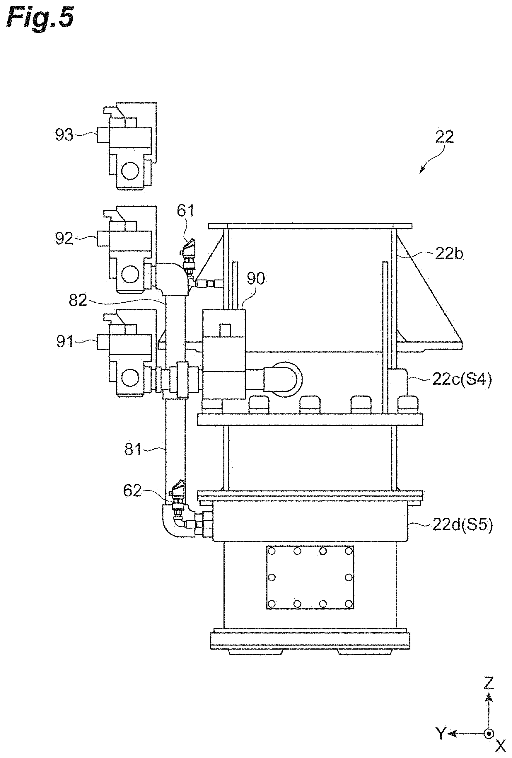
[0037] FIG. 5 is a schematic diagram on a left side of a compressed air supply structure related to an upper sand tank.
[0038] FIG. 6 is a schematic diagram on the back of the compressed air supply structure related to the upper sand tank.
[0039] FIG. 7 is a schematic diagram on the upper surface side of the compressed air supply structure related to the upper sand tank.
[0040] FIG. 8 is a schematic diagram on a left side of the compressed air supply structure related to a first lower sand tank and a second lower sand tank.
[0041] FIG. 9 is a schematic diagram on the back of the compressed air supply structure related to the first lower sand tank and the second lower sand tank.
[0042] FIG. 10 is a partially enlarged view of a lower portion of the apparatus in FIG. 8.
[0043] FIG. 11 is a sectional view of an inspection door.
[0044] FIG. 12 shows an example of connection of a third pressure detector.
[0045] FIG. 13 is a flowchart illustrating a molding process of the flaskless molding machine according to one embodiment.
[0046] FIG. 14 is a functional block diagram of the flaskless molding machine according to one embodiment.
[0047] FIG. 15 shows an example of a graph of a control signal for an electro-pneumatic proportional valve and detection results of the pressure detectors.
[0048] FIG. 16 shows an example of a graph indicating the detection result of the pressure detector and a threshold.
[0049] FIG. 17 shows an example of comparison between a preliminarily stored detection result and a detection result this time.
[0050] FIG. 18 shows screen examples displayed by a display unit.
DESCRIPTION OF EMBODIMENTS
[0051] Hereinafter, embodiments are described with reference to the drawings. The identical or corresponding portions in the diagrams are assigned identical signs, and redundant description is omitted. Hereinafter, the horizontal directions are assumed as X-axis and Y-axis directions, and the vertical direction (upward and downward direction) is assumed as a Z-axis direction.
[0052] [Overview of Flaskless Molding Machine]
[0053] FIG. 1 is a perspective view on a front side of a flaskless molding machine according to one embodiment. A flaskless molding machine 1 is a molding machine that forms a flaskless upper mold and lower mold. As shown in FIG. 1, the flaskless molding machine 1 includes a molding unit A1, and a conveyance unit A2. In the molding unit A1, an upper flask and a lower flask that have box shapes and are movable in the vertical direction (Z-axis direction) are disposed. The conveyance unit A2 introduces a match plate where models are arranged, to the molding unit A1. The upper flask and the lower flask of the molding unit A1 are moved to be close to each other, and clamp the match plate. The inside of the upper flask and the inside of the lower flask are filled with mold sand. The mold sand filled in the upper flask and the lower flask are pressurized in the vertical direction by a squeeze mechanism included in the molding unit A1, and the upper mold and the lower mold are simultaneously formed. Subsequently, an upper mold and a lower mold are removed from the upper flask and the lower flask, respectively, and are conveyed to the outside of the machine. As described above, the flaskless molding machine 1 forms the flaskless upper mold and lower mold.
[0054] [Frame Structure]
[0055] FIG. 2 is a front view of the flaskless molding machine 1 according to one embodiment. FIG. 3 is a schematic diagram on the left side of the flaskless molding machine according to one embodiment. As shown in FIGS. 2 and 3, the flaskless molding machine 1 includes an upper frame 10, a lower frame 11, and four guides 12 that connect the upper frame 10 and the lower frame 11. As for the guides 12, their upper ends are connected to the upper frame 10, and their lower ends are connected to the lower frame 11. The frame of the molding unit A1 described above is made up of the upper frame 10, the lower frame 11 and the four guides 12.
[0056] On a side of the frame of the molding unit A1 (in the negative direction on the X-axis), a support frame 13 (FIG. 2) of the conveyance unit A2 is disposed. Furthermore, on a side of the frame of the molding unit A1 (the positive direction on the Y-axis), a support frame 14 (FIG. 3) extending in the vertical direction is disposed. The support frame 14 supports a first lower sand tank described later.
[0057] [Upper Flask and Lower Flask]
[0058] The flaskless molding machine 1 includes an upper flask 15. The upper flask 15 is a box-shaped frame where the upper end and the lower end are open. The upper flask 15 is movably attached to the four guides 12. The upper flask 15 is supported by an upper flask cylinder 16 attached to the upper frame 10, and vertically moves along the guides 12 according to the operation of the upper flask cylinder 16.
[0059] The flaskless molding machine 1 includes a lower flask 17 disposed below the upper flask 15. The lower flask 17 is a box-shaped frame where the upper end and the lower end are open. The lower flask 17 is movably attached to the four guides 12. The lower flask 17 is supported by two lower flask cylinders 18 (FIG. 2) attached to the upper frame 10, and vertically moves along the guides 12 according to the operation of the lower flask cylinders 18. Hereinafter, a region encircled by the guides 12 is also called a formation position.
[0060] A match plate 19 (FIG. 2) is introduced between the upper flask 15 and the lower flask 17, from the conveyance unit A2. The match plate 19 is a plate-shaped member with models being disposed on both the surfaces thereof, and moves to and fro between the upper flask 15 and the lower flask 17. According to a specific example, the support frame 13 of the conveyance unit A2 includes rails toward a formation position, a conveyance plate 20 having rollers disposed on the rails, and a conveyance cylinder 21 that operates the conveyance plate 20. The match plate 19 is disposed on the conveyance plate 20, and is disposed at the formation position between the upper flask 15 and the lower flask 17 by the operation of the conveyance cylinder 21. The upper flask 15 and the lower flask 17 can clamp the disposed match plate 19, in the vertical direction. Hereinafter, a region on the support frame 13 is also called a retracted position.
[0061] [Sand Tank]
[0062] The flaskless molding machine 1 includes an upper sand tank 22 disposed above the upper flask 15. The upper sand tank 22 is attached to the upper frame 10. More specifically, the upper sand tank 22 is statically fixed to the upper frame 10. The upper sand tank 22 includes a storage chamber S1 that internally stores mold sand to be supplied to the upper flask 15. The upper sand tank 22 is open at its upper end and lower end. The upper end of the upper sand tank 22 is provided with a slide gate 23 that slides a plate-shaped shield member in the horizontal direction (the positive and negative directions on the X-axis). The upper sand tank 22 is configured so that its upper end can be opened and closed by the operation of the slide gate 23. A mold sand loading chute 24 that loads mold sand is fixedly disposed above the upper sand tank 22. The mold sand loading chute 24 is described later. When the slide gate 23 is in an open state, the mold sand is supplied through the mold sand loading chute 24 to the upper sand tank 22.
[0063] The lower end of the upper sand tank 22 is open, and an upper plate 25 (FIG. 3) is attached to the opening at the lower end. The upper plate 25 is a plate-shaped member, and has at least one supply port through which the upper sand tank 22 and the inside of the upper flask 15 communicate with each other. The mold sand in the upper sand tank 22 is supplied through the supply port of the upper plate 25 into the upper flask 15. The upper plate 25 has a size substantially identical to the size of the opening of the upper flask 15. The upper flask 15 moves in the upward direction, thereby causing the upper plate 25 to enter the inside of the upper flask 15. The upper flask 15 moves in the downward direction, thereby retracting the upper plate 25 from the upper flask 15. As described above, the upper plate 25 is configured to be capable of entering and being retracted from the inside of the upper flask 15. The details of the upper plate 25 are described later.
[0064] The upper sand tank 22 communicates with a compressed air source (not shown). According to a specific example, the upper sand tank 22 communicates with pipes 80 to 83 (FIGS. 2 and 5 to 7) for supplying compressed air, and communicates with the compressed air source through the pipes 80 to 83. The pipes 80 to 83 are provided with electro-pneumatic proportional valves 90 to 93 (examples of control valves in FIGS. 2 and 5 to 7). The electro-pneumatic proportional valve 92 not only switches supply and stop of compressed air but also automatically adjusts the valve opening degree according to the pressure on the output side. Accordingly, the compressed air at a predetermined pressure is supplied to the upper sand tank 22. When the slide gate 23 is in a closed state, compressed air is blown into the upper sand tank 22. The mold sand in the upper sand tank 22 is supplied, together with the compressed air, through the supply port of the upper plate 25 into the upper flask 15. Details of a compressed air supply mechanism are described later.
[0065] The storage chamber S1 of the upper sand tank 22 includes, on its inner surface, a first permeation member 22a (FIG. 3) having a plurality of pores that allow the compressed air to pass. Accordingly, the compressed air is supplied through the entire surface of the first permeation member 22a to the entire storage chamber S1, thereby improving the fluidity of the mold sand. The first permeation member 22a may be formed of a porous material. The upper sand tank 22 communicates with a pipe 29 (FIG. 2) for discharging the compressed air. The compressed air passes through the first permeation member 22a when being discharged through the pipe 29. The first permeation member 22a does not allow the mold sand to pass but allows the compressed air to pass. Consequently, the mold sand can be prevented from being discharged to the outside of the upper sand tank 22.
[0066] The flaskless molding machine 1 includes a lower sand tank that stores mold sand to be supplied into the lower flask 17. According to an example, the lower sand tank is divided into a first lower sand tank 30 (FIG. 3) and a second lower sand tank 31 (FIG. 3). The first lower sand tank 30 is disposed on a side of the upper sand tank 22. The first lower sand tank 30 includes a storage chamber S2 that internally stores mold sand to be supplied to the lower flask 17.
[0067] The first lower sand tank 30 is supported by the support frame 14, and is movably attached to a vertically extending guide 12A (FIG. 1) provided for the support frame 14. More specifically, the first lower sand tank 30 is supported by a lower tank cylinder (adjustment drive unit) 32 (FIG. 3) attached to the upper frame 10, and vertically moves along the guide 12A according to the operation of the lower tank cylinder 32.
[0068] The first lower sand tank 30 is open at its upper end. The first lower sand tank 30 is provided with a slide gate 33 (FIG. 3) that slides a plate-shaped shield member in the horizontal direction (the positive and negative directions on the X-axis), at the upper end. The first lower sand tank 30 is configured so that its upper end can be opened and closed by the operation of the slide gate 33. A hopper 34 (FIG. 3) for loading mold sand is fixedly disposed above the first lower sand tank 30. The communication relationship between the hopper 34 and the mold sand loading chute 24 is described later. When the slide gate 33 is in an open state, the mold sand is supplied through the hopper 34 to the first lower sand tank 30.
[0069] The first lower sand tank 30 is bent at its lower end in the horizontal direction (the negative direction on the Y-axis), and, at its distal end, a first communication port 35 (FIG. 3) for discharging the stored mold sand is formed. The first communication port 35 is configured so that this port can communicate with an after-mentioned second communication port of the second lower sand tank 31 at a predetermined height (communication position). The mold sand is supplied through the first communication port 35 to the second lower sand tank 31. The distal end of the first lower sand tank 30 is provided with a first block plate 36 (FIG. 3) that extends in the vertical direction. When an after-mentioned second communication port of the second lower sand tank 31 is not at a communication position, this port is shielded by the first block plate 36.
[0070] The first lower sand tank 30 communicates with the compressed air source (not shown). According to a specific example, the first lower sand tank 30 communicates with pipes 84 to 87 (FIG. 9) for supplying compressed air, and communicates with the compressed air source through the pipes 84 to 87. The pipes 84 to 87 are provided with electro-pneumatic proportional valves 94 to 97 (FIG. 9). Accordingly, the compressed air at a predetermined pressure is supplied to the first lower sand tank 30. When the slide gate 33 is in the closed state and the after-mentioned second communication port of the second lower sand tank 31 is at the communication position, the compressed air is supplied into the first lower sand tank 30. The mold sand in the first lower sand tank 30 is supplied, together with the compressed air, through the first communication port 35 into the second lower sand tank 31. Details of the compressed air supply mechanism are described later.
[0071] The storage chamber S2 of the first lower sand tank 30 is provided, on its inner surface, with a second permeation member 30a (FIG. 3) having a plurality of pores that allow the compressed air to pass. Accordingly, the compressed air is supplied through the entire surface of the second permeation member 30a to the entire storage chamber S2, thereby improving the fluidity of the mold sand. The second permeation member 30a may be formed of a porous material. The first lower sand tank 30 communicates, at its side, with a pipe (not shown) for discharging the compressed air. The compressed air passes through the second permeation member 30a when being discharged through the pipe. The second permeation member 30a does not allow the mold sand to pass but allows the compressed air to pass. Consequently, the mold sand can be prevented from being discharged to the outside of the first lower sand tank 30.
[0072] The second lower sand tank 31 is disposed below the lower flask 17. The second lower sand tank 31 includes a storage chamber S3 that internally stores mold sand to be supplied to the lower flask 17. The second lower sand tank 31 is movably attached to the four guides 12, and is supported in a vertically movable manner by a vertically extending squeeze cylinder (drive unit) 37.
[0073] At a side portion of the second lower sand tank 31, a second communication port 38 (FIG. 3) that can communicate with the first communication port 35 of the first lower sand tank is formed. The second communication port 38 is configured so that this port can communicate with the first communication port 35 of the first lower sand tank 30 at a predetermined height (communication position). The communication position has a height at which the first communication port 35 and the second communication port 38 communicate with each other and, more specifically, is a position at which the first communication port 35 and the second communication port 38 are disposed concentrically with each other. The first communication port 35 and the second communication port 38 communicate with each other on a communication plane along the vertical direction.
[0074] The first lower sand tank 30 and the second lower sand tank 31 are in a state of communicating with each other through communication between the first communication port 35 and the second communication port 38 being at the predetermined communication position. The mold sand is supplied through the first communication port 35 and the second communication port 38 from the first lower sand tank 30 to the second lower sand tank 31. The second communication port 38 of the second lower sand tank 31 is provided with a vertically extending second block plate 39 (FIG. 3). The opposite sides of the first communication port 35 of the first lower sand tank 30 are provided with guide rails (not shown) that guide a second block plate 39. The second block plate 39 is guided by the guide rails, thereby allowing the first communication port 35 and the second communication port 38 to be guided to the communication position without being inclined from each other. When the first communication port 35 of the first lower sand tank 30 is not at the communication position, this port is shielded by the second block plate 39.
[0075] It should be noted that the flaskless molding machine 1 may include a sealing mechanism that hermetically seals the communication planes of the first communication port 35 and the second communication port 38. For example, the sealing mechanism is provided on the first communication port 35 side.
[0076] The upper end of the second lower sand tank 31 is open, and a lower plate 40 (FIG. 3) is attached to the opening at the upper end. The lower plate 40 is a plate-shaped member, and has at least one supply port through which the second lower sand tank 31 and the inside of the lower flask 17 communicate with each other. The mold sand in the second lower sand tank 31 is supplied through the supply port of the lower plate 40 and an after-mentioned lower filling frame into the lower flask 17.
[0077] [Lower Filling Frame]
[0078] The flaskless molding machine 1 includes, for example, a lower filling frame 41. The lower filling frame 41 is disposed below the lower flask 17. The lower filling frame 41 is a box-shaped frame where the upper end and the lower end are open. The opening at the upper end of the lower filling frame 41 communicates with the opening at the lower end of the lower flask 17. The lower filling frame 41 is configured so that its inside can accommodate the second lower sand tank 31. The lower filling frame 41 is supported in a vertically movable manner by a lower filling frame cylinder 42 fixed to the second lower sand tank 31. The lower plate 40 has a size substantially identical to each of the sizes of openings of the lower filling frame 41 and the lower flask 17. A position where the vertically movable lower filling frame 41 internally accommodates the second lower sand tank 31 and the lower plate 40 is an original position (initial position), and serves as a descending end. The lower filling frame 41 moves in the upward direction, thereby retracting the lower plate 40 from the lower filling frame 41. The lower filling frame 41 having moved in the upward direction is moved in the downward direction, thereby allowing the lower plate 40 to enter the inside of the lower filling frame 41. As described above, the lower plate 40 is configured to be capable of entering and being retracted from the inside of the lower filling frame 41 (movable to and fro). The flaskless molding machine 1 can reduce the stroke of the lower flask 17 by comprising the lower filling frame 41. Consequently, the flaskless molding machine having a lower machine height can be achieved in comparison with a case of not comprising the lower filling frame 41. Furthermore, as the flaskless molding machine 1 can reduce the stroke of the lower flask 17 by comprising the lower filling frame 41, the molding time of the pair of the upper mold and the lower mold can be reduced.
[0079] It should be noted that the flaskless molding machine 1 does not necessarily include the lower filling frame 41. In this case, the lower plate 40 is configured to be capable of entering and being retracted from the inside of the lower flask 17 (movable to and fro). The descending end of the vertically movable lower flask 17 is the original position (initial position). That is, the lower plate 40 enters the inside of the lower flask 17 by moving in the upward direction relatively more than the lower flask 17 moving in the upward direction. The lower plate 40 is retracted from the lower flask 17 by moving in the downward direction relatively more than the lower flask 17.
[0080] [Molding Space and Squeeze]
[0081] The molding space (upper molding space) of the upper mold is formed by the upper plate 25, the upper flask 15 and the match plate 19. The molding space (lower molding space) of the lower mold is formed by the lower plate 40, the lower flask 17 and the match plate 19. The upper molding space and the lower molding space are formed when the upper flask cylinder 16, the lower flask cylinders 18 and the squeeze cylinder 37 are operated and the upper flask 15 and the lower flask 17 clamp the match plate at a predetermined height. In a case where the flaskless molding machine 1 includes the lower filling frame 41, the lower molding space may be formed by the lower plate 40, the lower flask 17, the lower filling frame 41 and the match plate 19.
[0082] The upper molding space is filled with the mold sand stored in the upper sand tank 22, through the upper plate 25. The lower molding space is filled with the mold sand stored in the second lower sand tank 31, through the lower plate 40. Compressed air is used for filling. A process of filling the upper molding space and the lower molding space with the mold sand while causing the mold sand to flow using the compressed air is called aeration. FIG. 4 is a schematic diagram on the left side of the flaskless molding machine in the aeration process. As shown in FIG. 4, when the upper flask 15 and the lower flask 17 clamp the match plate 19 at a predetermined height, the mold sand is supplied by the compressed air into the molding space.
[0083] The CB of the mold sand with which the upper molding space and the lower molding space are filled may be set in a range from 30% to 42%. The compressive strength of the mold sand with which the upper molding space and the lower molding space are filled may be set in a range from 8 to 15 N/cm.sup.2. It should be noted that as the thickness of the mold to be formed is changed according to the model shape and the CB (compactability) of the mold sand, the height of a target of the second lower sand tank 31 is changed according to the thickness of the mold. That is, the height of the second communication port 38 of the second lower sand tank 31 is changed. At this time, the height of the first communication port 35 of the first lower sand tank 30 is adjusted to be at the communication position of the second communication port 38 of the second lower sand tank 31 by the lower tank cylinder 32. Such adjustment can be achieved by an after-mentioned control device 50 (FIG. 3).
[0084] In a state where the upper molding space and the lower molding space are filled with the mold sand, the squeeze cylinder 37 performs squeezing with the upper plate 25 and the lower plate 40 by moving the second lower sand tank 31 upward. Accordingly, a pressure is applied to the mold sand in the upper molding space, and the upper mold is formed. At the same time, a pressure is applied to the mold sand in the lower molding space, and the lower mold is formed.
[0085] [Mold Sand Loading Chute]
[0086] The mold sand loading chute 24 is open at the upper end, and is bifurcated at the lower end. The upper end is provided with a switch damper 43. The switch damper 43 changes its inclination direction so that the mold sand can fall to any one of the bifurcated lower end portions. One lower end portion of the mold sand loading chute 24 is fixed to the upper portion of the upper sand tank 22, and the other lower end portion of the mold sand loading chute 24 is accommodated in the hopper 34 and is not fixed. Since the lower end portion on the first lower sand tank 30 side is not fixed as described above, the lower tank cylinder 32 can control the height of the first communication port 35 of the first lower sand tank 30 independently from the upper sand tank 22.
[0087] [Compressed Air Supply Structure]
[0088] The upper sand tank 22, the first lower sand tank 30 and the second lower sand tank 31 each include at least one supply chamber that communicates with the compressed air source. "Communicate(s)" means connection allowing air to pass through. The supply chamber may be disposed in such a way as to surround the storage chamber. The storage chamber and the supply chamber communicate with each other through a through-hole. Compressed air is blown from the compressed air source into the supply chamber, and is blown from the supply chamber into the storage chamber through the permeation members or ventholes.
[0089] Hereinafter, the compressed air supply structure at each tank is described. First, the compressed air supply structure at the upper sand tank 22 is described. FIG. 5 is a schematic diagram on the left side of the compressed air supply structure related to the upper sand tank. FIG. 6 is a schematic diagram on the back of the compressed air supply structure related to the upper sand tank. FIG. 7 is a schematic diagram on the upper surface side of the compressed air supply structure related to the upper sand tank.
[0090] As shown in FIGS. 5 to 7, the upper sand tank 22 includes a first supply chamber S4 disposed nearer to the upper end than the center of the upper sand tank 22, and a second supply chamber S5 disposed nearer to the lower end than the center of the upper sand tank 22, for example. The center of the upper sand tank 22 is the center of the upper sand tank 22 in the axial direction. The first supply chamber S4 and the second supply chamber S5 are disposed on a side of the storage chamber S1. The first supply chamber S4 and the second supply chamber S5 are spaces provided in such a way as to surround the storage chamber S1. The first supply chamber S4 is defined between a side wall 22b of the storage chamber S1 and a pipe member 22c provided outside of the side wall 22b of the storage chamber S1. The second supply chamber S5 is defined between the side wall 22b of the storage chamber S1 and a pipe member 22d provided outside of the side wall 22b of the storage chamber S1.
[0091] The pipes 80 and 83 communicate with the first supply chamber S4. The pipes 80 and 83 are connected at the positions of the pipe member 22c opposite to each other. The pipes 80 and 83 communicate with a main pipe 100 that communicates with the compressed air source. The pipe 80 is provided with an electro-pneumatic proportional valve 90. The pipe 83 is provided with an electro-pneumatic proportional valve 93. The electro-pneumatic proportional valves 90 and 93 are disposed on a side of the upper sand tank 22. The electro-pneumatic proportional valves are valves that are connected to the after-mentioned control device 50, and open and close on the basis of a control signal of the control device 50. The first supply chamber S4 communicates with the storage chamber S1 via a through-hole (not shown). When the electro-pneumatic proportional valves 90 and 93 are opened, the compressed air flows from the main pipe 100 through the pipes 80 and 83 and is supplied into the first supply chamber S4. The compressed air is blown from the first supply chamber S4 through the through-hole and the first permeation member 22a into the storage chamber S1. It should be noted that a plurality of through-holes may be formed in the side wall 22b of the storage chamber S1. For example, the plurality of through-holes may be formed in such a way as to surround the storage chamber S1. In this case, the compressed air is allowed to be uniformly blown toward the storage chamber S1 in the circumferential directions.
[0092] The pipes 81 and 82 communicate with the second supply chamber S5. The pipes 81 and 82 communicate with one side of the pipe member 22d. The pipes 81 and 82 communicate with the main pipe 100 that communicates with the compressed air source. The pipe 81 is provided with the electro-pneumatic proportional valve 91. The pipe 82 is provided with the electro-pneumatic proportional valve 92. The electro-pneumatic proportional valves 91 and 92 are disposed on a side of the upper sand tank 22. The second supply chamber S5 communicates with the storage chamber S1 via a through-hole (not shown). When the electro-pneumatic proportional valves 91 and 92 are opened, the compressed air flows from the main pipe 100 through the pipes 81 and 82 and is supplied into the second supply chamber S5.
[0093] The compressed air is blown from the second supply chamber S5 through the through-hole and the first permeation member 22a into the storage chamber S1. It should be noted that a plurality of through-holes may be formed in the side wall 22b of the storage chamber S1. For example, the plurality of through-holes may be formed in such a way as to surround the storage chamber S1. In this case, the compressed air is allowed to be uniformly blown toward the storage chamber S1 in the circumferential directions.
[0094] Next, the compressed air supply structure at the first lower sand tank 30 and the second lower sand tank 31 is described. FIG. 8 is a schematic diagram on a left side of the compressed air supply structure related to the first lower sand tank and the second lower sand tank. FIG. 9 is a schematic diagram on the back of the compressed air supply structure related to the first lower sand tank and the second lower sand tank. FIG. 10 is a partially enlarged view of a lower portion of the apparatus in FIG. 8.
[0095] As shown in FIGS. 8 to 10, the first lower sand tank 30 includes a third supply chamber S6 disposed at the center of the first lower sand tank 30, a fourth supply chamber S7 disposed nearer to the upper end than the center of the first lower sand tank 30, and a fifth supply chamber S8 disposed nearer to the lower end than the center of the first lower sand tank 30. The center of the first lower sand tank 30 is the center of the first lower sand tank 30 in the axial direction. The third supply chamber S6 and the fourth supply chamber S7 are disposed on a side of the storage chamber S2. The fifth supply chamber S8 is provided at a curved lower end of the first lower sand tank 30.
[0096] The third supply chamber S6 and the fourth supply chamber S7 are spaces provided in such a way as to surround the storage chamber S2. The third supply chamber S6 is defined between a side wall 30c of the storage chamber S2 and a pipe member 30d provided outside of the side wall 30c of the storage chamber S2. The fourth supply chamber S7 is defined between the side wall 30c of the storage chamber S2 and a pipe member 30g provided outside of the side wall 30c of the storage chamber S2.
[0097] The pipe 84a communicates with the third supply chamber S6. The pipe 84a communicates with one side of the pipe member 30d. The pipe 84a communicates with the main pipe 100 that communicates with the compressed air source via the pipe 84. The pipe 84 is provided with an electro-pneumatic proportional valve 94. The electro-pneumatic proportional valve 94 is disposed on a side of the first lower sand tank 30. The third supply chamber S6 communicates with the storage chamber S2 via a through-hole (not shown). When the electro-pneumatic proportional valve 94 is opened, the compressed air flows from the main pipe 100 through the pipes 84 and 84a and is supplied into the third supply chamber S6. The compressed air is blown from the third supply chamber S6 through the through-hole and the second permeation member 30a into the storage chamber S2. It should be noted that a plurality of through-holes may be formed in the side wall 30c of the storage chamber S2. For example, the plurality of through-holes may be formed in such a way as to surround the storage chamber S2. In this case, the compressed air is allowed to be uniformly blown toward the storage chamber S2 in the circumferential directions.
[0098] A pipe 84b communicates with the fourth supply chamber S7. The pipe 84b communicates with one side of the pipe member 30g. The pipe 84b communicates with the main pipe 100 that communicates with the compressed air source via the pipe 84. The pipe 84 is provided with the electro-pneumatic proportional valve 94. That is, the electro-pneumatic proportional valve 94 controls the flow rates of both the pipes 84a and 84b. The electro-pneumatic proportional valve 94 is disposed on a side of the first lower sand tank 30. The fourth supply chamber S7 communicates with the storage chamber S2 via a through-hole (not shown). When the electro-pneumatic proportional valve 94 is opened, the compressed air flows from the main pipe 100 through the pipes 84 and 84b and is supplied into the fourth supply chamber S7. The compressed air is blown from the fourth supply chamber S7 through the through-hole and the second permeation member 30a into the storage chamber S2. It should be noted that a plurality of through-holes may be formed in the side wall 30c of the storage chamber S2. For example, the plurality of through-holes may be formed in such a way as to surround the storage chamber S2. In this case, the compressed air is allowed to be uniformly blown toward the storage chamber S2 in the circumferential directions.
[0099] The fifth supply chamber S8 is formed in an inspection door 70. The inspection door 70 is a door that is opened and closed during maintenance of the first lower sand tank 30. FIG. 11 is a sectional view of the inspection door. As shown in FIG. 11, the inspection door 70 is a hollow member in which the fifth supply chamber S8 is defined. A supply port 70b that communicates with a pipe 85 for supplying compressed air is formed on an outer side surface 70a of the inspection door 70. Through-holes 70d for supplying compressed air into the storage chamber S2 are formed on an inner surface side 70c of the inspection door 70. The number of formed through-holes 70d may be one or more. Ventholes 70e where slits are formed are fit in the through-holes 70d.
[0100] As shown in FIGS. 8 to 10, the pipe 85 communicates with the fifth supply chamber S8. The pipe 85 communicates with the supply port 70b. The pipe 85 communicates with the main pipe 100 that communicates with the compressed air source. The pipe 85 is provided with the electro-pneumatic proportional valve 95. The electro-pneumatic proportional valve 95 is disposed on a side of the first lower sand tank 30. The fifth supply chamber S8 communicates with the storage chamber S2 via the plurality of ventholes 70e. When the electro-pneumatic proportional valve 95 is opened, the compressed air flows from the main pipe 100 through the pipe 85 and is supplied into the fifth supply chamber S8. The compressed air is blown from the fifth supply chamber S8 through the plurality of ventholes 70e into the storage chamber S2.
[0101] The second permeation member 30a does not intervene at the flow path from the fifth supply chamber S8 to the storage chamber S2. At the curved lower end of the first lower sand tank 30, owing to the shape thereof, the abrasion of the permeation member disposed in the storage chamber S2 tends to be larger than that at another arrangement position. Accordingly, in the storage chamber S2 at the curved lower end of the first lower sand tank 30, the plurality of ventholes 70e instead of the second permeation member 30a are adopted. Consequently, at the bent lower end of the first lower sand tank 30, clogging of the permeation member is prevented from occurring.
[0102] The second lower sand tank 31 includes, for example, a sixth supply chamber S9 and a seventh supply chamber S10 that are disposed at a bottom of the storage chamber S3. The sixth supply chamber S9 is defined in a pipe member 71. The pipe member 71 is disposed at a bottom of the second communication port 38 of the second lower sand tank 31. At the pipe member 71, a supply port 71a that communicates with a pipe for supplying compressed air, and through-holes 71b for supplying compressed air into the storage chamber S3 are formed. The number of formed through-holes 71b may be one or more. Ventholes (not shown) where slits are formed are fit in the through-holes 71b. At the pipe member 72, a supply port 72a that communicates with a pipe for supplying compressed air, and through-holes 72b for supplying compressed air into the storage chamber S3 are formed. The number of formed through-holes 72b may be one or more. Ventholes (not shown) where slits are formed are fit in the through-holes 72b.
[0103] A pipe 86 communicates with the sixth supply chamber S9. The pipe 86 communicates with the supply port 71a. The pipe 86 communicates with the main pipe 100 that communicates with the compressed air source. The pipe 86 is provided with the electro-pneumatic proportional valve 96. The sixth supply chamber S9 communicates with the storage chamber S3 via a plurality of ventholes. When the electro-pneumatic proportional valve 96 is opened, the compressed air flows from the main pipe 100 through the pipe 86 and is supplied into the sixth supply chamber S9. The compressed air is blown from the sixth supply chamber S9 through the plurality of ventholes into the storage chamber S3.
[0104] A pipe 87 communicates with the seventh supply chamber S10. The pipe 87 communicates with the supply port 72a. The pipe 87 communicates with the main pipe 100 that communicates with the compressed air source. The pipe 87 is provided with the electro-pneumatic proportional valve 97. The seventh supply chamber S10 communicates with the storage chamber S3 via a plurality of ventholes. When the electro-pneumatic proportional valve 97 is opened, the compressed air flows from the main pipe 100 through the pipe 87 and is supplied into the seventh supply chamber S10. The compressed air is blown from the seventh supply chamber S10 through the plurality of ventholes into the storage chamber S3.
[0105] Any permeation member does not intervene at the flow path from the sixth supply chamber S9 and the seventh supply chamber S10 to the storage chamber S2. In the second lower sand tank 31, the abrasion of the permeation member disposed in the storage chamber tends to be higher than the abrasions of the other tanks. Accordingly, in the storage chamber S3 of the second lower sand tank 31, the plurality of ventholes are adopted instead of the permeation member. Consequently, in the second lower sand tank 31, clogging of the permeation member is prevented from occurring.
[0106] [Pressure Detectors]
[0107] The flaskless molding machine 1 may include at least one pressure detector. At least one pressure detector detects the pressure of at least one tank among the upper sand tank 22, the first lower sand tank 30 and the second lower sand tank 31. The pressure detector includes, for example, a main body, a diaphragm that is stored in the main body and is deformed by the pressure, and a strain gauge that outputs a signal according to the deformation of the diaphragm. The pressure detector may include a display (e.g., an LED (Light Emitting Diode) display) or the like on the main body. Any of various methods may be adopted as a method of attaching the pressure detector. For example, attachment may be made onto a side wall of the storage chamber. Alternatively, attachment may be made onto a side wall of a space that communicates with the storage chamber.
[0108] Hereinafter, the arrangement of the pressure detector at each tank is described. First, the arrangement of the pressure detector at the upper sand tank 22 is described. As shown in FIG. 3, the upper sand tank 22 is provided with a first pressure detector 61 and a second pressure detector 62. The first pressure detector 61 detects the pressure of the first supply chamber S4. The second pressure detector 62 detects the pressure of the second supply chamber S5. As described above, at the upper sand tank 22, the pressure in a space (the first supply chamber S4 and the second supply chamber S5) that is outside of the storage chamber S1 and communicates with the storage chamber S1 via the first permeation member 22a is detected.
[0109] Next, the arrangement of the pressure detector at the first lower sand tank 30 is described. As shown in FIG. 3, the first lower sand tank 30 is provided with a third pressure detector 63, a fourth pressure detector 64 and a fifth pressure detector 65. The third pressure detector 63 detects the pressure in the third supply chamber S6 and the fourth supply chamber S7. The fourth pressure detector 64 detects the pressure in the storage chamber S2. The fifth pressure detector 65 detects the pressure in the fifth supply chamber S8. As described above, at the first lower sand tank 30, the pressure in the storage chamber S2 is directly detected, while the pressure in a space (the third supply chamber S6, the fourth supply chamber S7 and the fifth supply chamber S8) that is outside of the storage chamber S2 and communicates with the storage chamber S2 via the second permeation member 30a is detected. It should be noted that the pressure in the storage chamber S2 detected by the fourth pressure detector 64 is used as a reference pressure for preventing a reverse flow during discharge, which is described later.
[0110] Next, the arrangement of the pressure detector at the second lower sand tank 31 is described. As shown in FIG. 3, the second lower sand tank 31 is provided with a sixth pressure detector 66. The sixth pressure detector 66 detects the pressure in the storage chamber S3. It should be noted that the sixth pressure detector 66 may detect the pressure in a space that is outside of the storage chamber S3 and communicates with the storage chamber S3 via a vent or the like.
[0111] [Details of Attachment of Pressure Detectors]
[0112] The arrangement of the pressure detectors (the first pressure detector 61 to the third pressure detector 63 and the fifth pressure detector 65) that detect the pressures outside of the storage chambers is described. The forms of connection of these pressure detectors are the same. Accordingly, the third pressure detector 63 is typified and described. FIG. 12 shows an example of connection of the third pressure detector. As shown in FIG. 12, on the inner side of the side wall 30c of the first lower sand tank 30, the second permeation member 30a is attached via rubber members 30f. In the side wall 30c, a through-hole 30e is formed. The pipe member 30d defining the third supply chamber S6 is attached to the outside of the side wall 30c at a position corresponding to the through-hole 30e. The third supply chamber S6 communicates with the storage chamber S2 via the through-hole 30e and the second permeation member 30a. The third supply chamber S6 is provided with a communication port (not shown) through which compressed air is supplied. The compressed air supplied through the communication port passes through the through-hole 30e and the second permeation member 30a, and is supplied into the storage chamber S2 of the first lower sand tank 30. As described above, the first pressure detector 61 to the third pressure detector 63 and the fifth pressure detector 65 detect the pressures of spaces that are outside of the storage chambers and communicate with the storage chambers via the permeation members.
[0113] [Control Device]
[0114] The flaskless molding machine 1 may include a control device 50 (an example of a control unit). The control device 50 is a computer that includes a control unit such as a processor, a storage unit such as a memory, an input and output unit such as an input device and a display device, and a communication unit such as a network card, and controls each of units of the flaskless molding machine 1, for example, a mold sand supply system, a compressed air supply system, a drive system, a power source system and the like. The control device 50 allows an operator to perform a command input operation and the like in order to manage the flaskless molding machine 1, using the input device, and can cause the display device to visualize and display the operation situations of the flaskless molding machine 1. Furthermore, the storage unit of the control device 50 stores a control program for allowing the processor to control various processes to be executed by the flaskless molding machine 1, and a program for causing each configuration unit of the flaskless molding machine 1 to execute processes according to a molding condition.
[0115] The control device 50 is connected to the first pressure detector 61 to the sixth pressure detector 66, and obtains a detection result of at least one of the pressure detectors. Control based on the pressure detection result is described later.
[0116] [Molding Process]
[0117] An overview of a molding process according to this embodiment is described. FIG. 13 is a flowchart illustrating the molding process of the flaskless molding machine according to one embodiment. The molding process shown in FIG. 13 is a process of molding a pair of the upper mold and the lower mold. The molding process shown in FIG. 13 is automatically activated with a condition that the attitude of the flaskless molding machine 1 is the original position (initial position). When the attitude of the flaskless molding machine 1 is not at the original position, this machine is manually operated to be moved to the original position. When an automatic activation button is pressed with the attitude (original position) of the flaskless molding machine 1 shown in FIG. 3, the molding process shown in FIG. 13 is started.
[0118] When the molding process is started, a shuttle-in process (S12) is performed first. In the shuttle-in process, the conveyance cylinder 21 moves the conveyance plate 20 mounted with the match plate 19 to a molding position.
[0119] Next, a flask setting process (S14) is performed. In the flask setting process, the upper flask cylinder 16, the lower flask cylinders 18 (FIG. 2), the lower filling frame cylinder 42 and the squeeze cylinder 37 are elongated and contracted in conformity with the thicknesses of the molds to be formed. Accordingly, the upper flask 15 is moved to the predetermined position, and the lower flask 17 comes into contact with the match plate 19, and subsequently, the lower flask 17 mounted with the match plate 19 is moved to the predetermined position, thereby achieving a state where the match plate 19 is clamped between the upper flask 15 and the lower flask 17. The second lower sand tank 31 and the lower filling frame 41 then rise, and the lower filling frame 41 comes into contact with the lower flask 17. The lower tank cylinder 32 is elongated and contracted to move the first lower sand tank 30 in the vertical direction, thereby achieving a state where the height of the first communication port 35 of the first lower sand tank 30 coincides with the height of the second communication port 38 of the second lower sand tank 31. At this time, the upper molding space and the lower molding space are in a state (height) determined by the control device 50.
[0120] Next, an aeration process (S16) is performed. As shown in FIG. 4, in the aeration process, the sealing mechanism seals the first communication port 35 of the first lower sand tank 30 and the second communication port 38 of the second lower sand tank 31. The slide gate 23 of the upper sand tank 22 and the slide gate 33 of the first lower sand tank 30 are then closed, and compressed air is supplied by the compressed air source and the electro-pneumatic proportional valves 90 to 97 into the upper sand tank 22, the first lower sand tank 30 and the second lower sand tank 31. Accordingly, the upper molding space and the lower molding space are filled with the mold sand while the mold sand is allowed to flow. For example, if the set pressure and time are satisfied, the aeration process is finished. It should be noted that after the aeration process is completed, a discharge process for the upper sand tank 22, the first lower sand tank 30 and the second lower sand tank 31 is performed.
[0121] Next, a squeeze process (S18) is performed. In the squeeze process, the sealing mechanism having been operated in the aeration process (S16) releases the sealing, and the squeeze cylinder 37 is further elongated, thereby further raising the second lower sand tank 31. Accordingly, the lower plate 40 attached to the second lower sand tank 31 enters the inside of the lower filling frame 41 and compresses the mold sand in the lower molding space, while the upper plate 25 enters the inside of the upper flask 15 and compresses the mold sand in the upper molding space. In a case where the squeeze cylinder 37 is controlled by an oil-hydraulic circuit, the squeeze process is finished when the oil pressure of the oil-hydraulic circuit can be determined to be the same as the set oil pressure, for example. In a case where during the squeeze process, the upper flask cylinder 16, the lower flask cylinders 18 and the lower filling frame cylinder 42 are controlled by the oil-hydraulic circuit, each cylinder is set as a free circuit. Accordingly, each cylinder yields to the squeeze force and is contracted.
[0122] Next, a model release process (S20) is performed. In the model release process, the lower filling frame cylinder 42 is contracted to lower the lower filling frame 41. Subsequently, the squeeze cylinder 37 is contracted and lowers the second lower sand tank 31, and subsequently lowers the lower flask 17 mounted with the match plate 19 and the conveyance plate 20. The model is then released from the upper flask 15. When the lower flask 17 is lowered to a fixed unit (not shown), the match plate 19 and the conveyance plate 20 are supported by the fixed unit. Accordingly, the model is released from the lower flask 17.
[0123] Next, a shuttle-out process (S22) is performed. In the shuttle-out process, the conveyance cylinder 21 is contracted, thereby moving the conveyance plate 20 to the retracted position. A core is disposed in the upper flask 15 or the lower flask 17 if necessary.
[0124] Next, a flask alignment process (S24) is performed. In the flask alignment process, the lower flask cylinders 18 are contracted and the squeeze cylinder 37 is elongated, thereby raising the lower flask 17 and the second lower sand tank 31 to align the flask.
[0125] Next, the flask release process (S26) is performed. In the flask release process, the upper flask cylinder 16 and the lower flask cylinders 18 are contracted, thereby raising the upper flask 15 and the lower flask 17 to the raised ends to release the flask.
[0126] Next, a first flask separating process (S28) is performed. In the first flask separating process, in a state where the mold is mounted on the lower plate 40 of the second lower sand tank 31, the squeeze cylinder 37 is contracted to lower the second lower sand tank 31. At this time, the lower flask cylinders 18 are elongated to lower the lower flask 17, and the mold is stopped at a position of not interfering with conveyance of the mold.
[0127] Next, a mold extrusion process (S30) is performed. In the mold extrusion process, an extrusion cylinder 48 (see FIG. 2) is elongated, thereby conveying the upper mold and the lower mold to the outside of the machine (e.g., a molding line).
[0128] Next, a second flask separating process (S32) is performed. In the second flask separating process, the lower flask cylinders 18 are elongated to return the lower flask 17 to the original position.
[0129] As described above, the process of forming the pair of the upper mold and the lower mold is thus finished,
[0130] [Detection of Pressures in Sand Tanks]
[0131] FIG. 14 is a functional block diagram of the flaskless molding machine according to one embodiment. As shown in FIG. 14, the flaskless molding machine 1 includes the first pressure detector 61 to the sixth pressure detector 66, the control device 50, a display unit 67, and the electro-pneumatic proportional valves 90 to 97.
[0132] The control device 50 is connected to the first pressure detector 61 to the sixth pressure detector 66, and can obtain a detection result. The detection result is information about the pressure output from at least one pressure detector among the first pressure detector 61 to the sixth pressure detector 66.
[0133] The control device 50 includes an operation unit 51, a communication unit 52, and a storage unit 53. The operation unit 51 is a configuration element that performs various operations related to pressure control, and is achieved by a processor, a memory and the like. The communication unit 52 is a configuration element that transmits information to the outside of the apparatus, and is achieved by a network card and the like.
[0134] The communication unit 52 processes data in conformity with a communication standard on the basis of an instruction by the operation unit 51, and outputs the data to the communication network 68. The communication network 68 may be of wireless communication or wired communication. The storage unit 53 is a configuration element that stores data, and is achieved by a memory and the like.
[0135] The display unit 67 is a device that can display information in a viewable state. The display unit 67 is a display device, for example. The display unit 67 may be fixed to the apparatus, or separated from the apparatus. The display unit 67 displays the detection result of at least one pressure detector on the basis of the control signal from the control device 50. The display unit 67 may display warning information on the basis of the control signal from the control device 50. The display unit 67 may be a touch panel that accepts an input operation by an operator. The display unit 67 may output the input operation by the operator to the control device 50.
[0136] Hereinafter, a control process by the control device 50 is described in association with each configuration element. [First data display process]
[0137] A first data display process is a process of causing the display unit 67 to display results detected by the first pressure detector 61 to the sixth pressure detector 66 during execution of the molding process in FIG. 13. The display timing may be in the middle of the molding process, or after the molding process. The operation unit 51 of the control device 50 causes the display unit 67 to display a graph representing the relationship between the pressure and time, as the detection result of the first pressure detector 61 to the sixth pressure detector 66. The operation unit 51 may cause the display unit 67 to display control information on the electro-pneumatic proportional valves 90 to 97, together with the detection result. The control information is information about control signals for the electro-pneumatic proportional valve. For example, the control signals for the electro-pneumatic proportional valves are signals obtained by converting control signals into pressures on the basis of a predetermined calculation expression. Such conversion is executed by the operation unit 51. The operation unit 51 of the control device 50 causes the display unit 67 to display the control information and the detection result in a manner allowing comparison. For example, the operation unit 51 of the control device 50 displays, on the screen, the control information and the detection result at the same timing. For example, the operation unit 51 displays comparison target data items on the same graph in an overlaid manner. The operation unit 51 may display the comparison target data items as separate graphs on the same screen. It should be noted that the manner allowing comparison is not limited to a case where the comparison target data items are displayed on the screen at the same timing. The comparison target data items may be alternately displayed on the screen.
[0138] FIG. 15 shows an example of a graph of the control signal for the electro-pneumatic proportional valve and the detection results of the pressure detectors. The graph shown in FIG. 15 indicates the detection result at the upper sand tank 22. The abscissa is the time. The ordinate is the pressure. In FIG. 15, the control signal for the electro-pneumatic proportional valve is converted into the pressure and is indicated by a broken line. That is, the broken line in the diagram is a target pressure. A time period from the rise to the fall of the waveform of the broken line is an aeration time period T1. In FIG. 15, the detection results are indicated by solid lines. A thick solid line is the detection result of the first pressure detector 61. A thin solid line is the detection result of the second pressure detector 62. The operator or the like can check the validity of the control on the basis of the graph shown in FIG. 15.
[0139] For example, in the graph shown in FIG. 15, in an early stage of the aeration time period T1, the pressure in the upper sand tank 22 increases. As indicated by timing E1 in the diagram, the increase in pressure temporarily stops. It is believed that the stop of increase in pressure occurs because mold sand flows in the upper sand tank 22. Subsequently, as indicated by timing E2 in the diagram, the pressure restarts to increase. It is believed that the reascending in pressure occurs because the filling with the mold sand is completed. After the time elapses from the timing E2, the pressure slightly increases to a constant value. The operator or the like can verify the length of the aeration time period T1 on the basis of the graph shown in FIG. 15. The operator or the like can set the length of the aeration time period T1 through an after-mentioned setting screen. For example, the operator or the like may adjust the aeration time period T1 so that the finish timing of the aeration time period T1 can approach the timing E2. The operator or the like may adjust the aeration time period T1 so that the finish timing of the aeration time period T1 can approach timing after lapse of a margin time period T2 from the timing E2. The margin time period T2 is a value defined on the basis of actual measurement. The margin time period T2 may be a value appropriately set by the operator or the like. Such adjustment can reduce the cycle time, and optimize the amount of air to be consumed.
[0140] [Second Data Display Process]
[0141] A second data display process is a process of causing the display unit 67 to display results detected by the first pressure detector 61 to the sixth pressure detector 66. The display timing is timing when clogging of the first permeation member 22a or the second permeation member 30a is checked, and is a maintenance time, for example. The operation unit 51 of the control device 50 causes the display unit 67 to display a graph representing the relationship between the pressure and time, as the detection result of at least one of the first pressure detector 61 to the third pressure detector 63, for example. The first pressure detector 61 to the third pressure detector 63 communicate with the storage chambers via the first permeation member 22a or the second permeation member 30a. Consequently, from the detection result of the pressures of the first pressure detector 61 to the third pressure detector 63, the clogging of the first permeation member 22a or the second permeation member 30a can be detected.
[0142] The clogging of the permeation member is determined by the operator or the like. To assist the determination by the operator or the like, a threshold may be displayed together with the detection result of the pressure. For example, the operation unit 51 of the control device 50 causes the display unit 67 to display the detection result of at least one pressure detector (the first pressure detector 61, the second pressure detector 62) at the upper sand tank 22 and a preset threshold in a manner allowing comparison. Alternatively, the operation unit 51 causes the display unit 67 to display the pressure detected by the third pressure detector 63 at the first lower sand tank 30 and a preset threshold in a manner allowing comparison. The preset threshold may be stored in the storage unit 53. For example, a value obtained by subtracting a predetermined value from an observed abnormal value may be set as the threshold and be stored in the storage unit 53. The control device 50 may obtain the threshold via a touch panel or the like, and store the threshold in the storage unit 53. The operation unit 51 may cause the display unit 67 to display control information on the electro-pneumatic proportional valves 90 to 94, together with the detection result. The control information is information about control signals for the electro-pneumatic proportional valve. For example, the control signals for the electro-pneumatic proportional valves are signals obtained by converting control signals into pressures on the basis of a predetermined calculation expression. Such conversion is executed by the operation unit 51.
[0143] FIG. 16 shows an example of a graph indicating the detection result of the pressure detector and the threshold. The graph shown in FIG. 16 indicates the detection result at the upper sand tank 22. The abscissa is the time. The ordinate is the pressure. In FIG. 16, a thick solid line is the abnormal value, a broken line is the threshold, and a thin solid line is the detection result of the pressure detector. When clogging occurs in the first permeation member 22a, the pressure increases and exceeds the threshold. The operator or the like can check the presence or absence of clogging of the permeation member on the basis of the graph shown in FIG. 16.
[0144] [Third Data Display Process]
[0145] A third data display process is a process of causing the display unit 67 to display results detected by the first pressure detector 61 to the sixth pressure detector 66 during execution of the molding process in FIG. 13. The display timing may be in the middle of the molding process, or after the molding process. The operation unit 51 of the control device 50 causes the display unit 67 to display a graph representing the relationship between the pressure and time, as the detection result of the first pressure detector 61 to the sixth pressure detector 66. The operation unit 51 may cause the display unit 67 to display control information on the electro-pneumatic proportional valves 90 to 97, together with the detection result. The control information is information about control signals for the electro-pneumatic proportional valve. For example, the control signals for the electro-pneumatic proportional valves are signals obtained by converting control signals into pressures on the basis of a predetermined calculation expression. Such conversion is executed by the operation unit 51.
[0146] The operation unit 51 of the control device 50 stores the detection results of the first pressure detector 61 to the sixth pressure detector 66 in the storage unit 53 at predetermined timing. The operation unit 51 then causes the display unit 67 to display the stored detection results and the detection results this time in a manner allowing comparison. For example, the operation unit 51 refers to the storage unit 53, obtains the preliminarily stored detection results, and obtains the detection results this time from the first pressure detector 61 to the sixth pressure detector 66. The operation unit 51 then displays, on the screen, the preliminarily stored detection results and the detection results this time at the same timing. For example, the operation unit 51 displays comparison target data items on the same graph in an overlaid manner. The operation unit 51 may display the comparison target data items as separate graphs on the same screen. It should be noted that the manner allowing comparison is not limited to a case where the comparison target data items are displayed on the screen at the same timing. The comparison target data items may be alternately displayed on the screen.
[0147] FIG. 17 shows an example of comparison between the preliminarily stored detection result and the detection results this time. The graphs shown in FIG. 17 indicate the detection results at the upper sand tank 22. The abscissa is the time. The ordinate is the pressure. A screen example (A) is a screen where a graph G1 of the preliminarily stored detection result is displayed. A screen example (B) is a screen where the graph G1 of the preliminarily stored detection result and a graph G2 of a detection result this time are displayed in an overlaid manner. The operator or the like can check the presence or absence of the difference from the previous process on the basis of the graph shown in FIG. 17.
[0148] [Setting Screen Display Process]
[0149] The operation unit 51 causes the display unit 67 to display a setting screen, as an example of the setting process. The setting screen is a screen for setting the aeration setting pressure and the time. The operation unit 51 then sets the aeration setting pressure and time on the basis of the operator's input information accepted through an input unit (not shown). For example, the operation unit 51 sets the aeration time period, the pressure, the threshold and the like. The setting is to store a target value in the storage unit 53, for example.
[0150] FIG. 18 shows screen examples displayed by the display unit. A screen example (A) is an example of a setting screen for setting the aeration time period. Icons IC1 for accepting an input operation for page transition are displayed at an upper portion of the screen example (A). Icons IC2 for accepting an input operation for calling applications or various functions are displayed at a lower portion of the screen. Setting targets and setting items are displayed at the center of the screen. An example of the setting target is the electro-pneumatic proportional valve. On the screen example (A), the electro-pneumatic proportional valves 90 and 93 and the electro-pneumatic proportional valves 90 and 93 are respectively displayed as objects OB1 and OB2. Examples of the setting items are aeration time periods and pressures. On the screen example (A), the aeration time periods and the pressures are displayed as objects OB3 to OB5. Objects OB3 to OB5 are items that can be input by the operator or the like.
[0151] Examples of the setting items are aeration time periods and pressures in an additional process. The additional process is not executed when the aeration process is normal. The additional process is a process executed to extend the aeration time period before the aeration process is determined to be abnormal. The details of the additional process are described later. On the screen example (A), the aeration time period and the pressure in the additional process are displayed as an object OB6. An object OB6 is an item that can be input by the operator or the like. Setting items acceptable at the object OB6 are setting values for the additional aeration. The operator or the like can perform setting related to aeration by inputting values in the objects OB3 to OB6.
[0152] [Warning Process]
[0153] The control device 50 issues a warning when detecting an abnormality. The warning is notification about the abnormality to the operator or the like. The control device 50 displays, on the display unit 67, a screen related to the warning as an example of the warning process. The control device 50 may output an alarm through a speaker, not shown, instead of the warning through display or together with the warning though the display.
[0154] One abnormality assumed in the flaskless molding machine through use of compressed air is a blow abnormality. The blow abnormality is "a phenomenon where a site without mold sand due to partial clogging at each supply port of the lower plate 40 occurs and the site serves as a path of the compressed air." At the site without mold sand, the air resistance is low. Accordingly, the compressed air is blown only through the site. Accordingly, if the blow abnormality occurs, the pressure does not increase. The control device 50 extends the aeration time period when normal filling with mold sand is not performed in the aeration process (additional process). That is, the control device 50 outputs the control signal to at least one electro-pneumatic proportional valve on the basis of the detection results of the first pressure detector 61 to the sixth pressure detector 66. In a more specific example, when the maximum pressure detected by the pressure detector in the aeration time period T.sub.1 in the aeration process does not reach a predetermined threshold, the control device 50 determines that normal filling with mold sand is not finished. The predetermined threshold is stored in the storage unit 53, for example. The control device 50 outputs the control signal to the electro-pneumatic proportional valve on the basis of the value set using the screen example (A) in FIG. 18, for example (the additional process of extending the aeration time period).
[0155] When the blow abnormality is resolved by the additional process, that is, when the maximum pressure detected by the pressure detector in the additional aeration time period reaches the predetermined threshold, the control device 50 determines that the process of filling with mold sand is normal and does not issue a warning. On the contrary, when the maximum pressure detected by the pressure detector in the additional aeration time period does not reach the predetermined threshold, the control device 50 issues warning information. The warning information is data related to a warning, is screen data when being output to the display unit 67, and is alarm data when being output to a speaker or the like. The control device 50 may stop the operation of the flaskless molding machine 1 when outputting the warning information. The screen example (B) in FIG. 18 is an example of the warning. The control device 50 causes the display unit 67 to display the content of the abnormality, the operation state of the flaskless molding machine 1, a countermeasure (handling method), a recovery (recovery method) or the like.
[0156] After the aeration time period T1 elapses, the control device 50 performs the discharge process. In the discharge process, the compressed air in the upper sand tank 22 is discharged and the pressure gradually decreases. If sand clogging is at a discharge mechanism, the reduction in pressure becomes sluggish in a discharge process time period T3 as indicated by a graph G3 in the screen example (B) in FIG. 17, for example. If the pressure detected by at least one pressure detector is not equal to or less than the predetermined threshold after lapse of a predetermined time period in a case of air discharge from the upper sand tank 22, the first lower sand tank 30 and the second lower sand tank 31, the control device 50 issues the warning information. Accordingly, the operator or the like can recognize a discharge abnormality.
[0157] It should be noted that the control device 50 may output the control signal so that at least one electro-pneumatic proportional valve is opened on the basis of the detection result of at least one pressure detector in the discharge process. According to such operation, the pressure in the supply chamber increases. Consequently, a reverse flow from a filling chamber to the supply chamber is prevented. The reverse flow of mold sand tends to occur at the sites where vents are disposed, that is, at the supply chambers S8 to S10. In the discharge process, the control device 50 outputs the control signal so that the electro-pneumatic proportional valves 95 to 97 can be opened, on the basis of the pressure detected by the fourth pressure detector 64, which serves as the reference. The control device 50 may open the electro-pneumatic proportional valves 95 to 97 in such a way as to achieve a higher pressure than the pressure detected by the fourth pressure detector 64 by a predetermined value (feedback process).
[0158] As described above, in the flaskless molding machine 1 according to this embodiment, the pressures in the upper sand tank 22, the first lower sand tank 30 and the second lower sand tank 31 are detected by the first pressure detector 61 to the sixth pressure detector 66. The detection results of the first pressure detector 61 to the sixth pressure detector 66 are then obtained by the control device 50. As described above, according to the flaskless molding machine 1, the situations in the sand tanks are obtained by obtaining the pressures in the tanks. As a result, excellent molds and casting products can be obtained.
[0159] According to the flaskless molding machine 1, in a case where the squeeze process is performed by the second lower sand tank moving in the vertical direction, the situations in the sand tanks can be appropriately grasped.
[0160] According to the flaskless molding machine 1, due to the arrangement of the first pressure detector 61 to the sixth pressure detector 66, the supply chambers S4 to S10 for supplying compressed air can be utilized. The flaskless molding machine 1 is not required to be provided with a through-hole or the like for pressure detection at the storage chambers S1 to S3, which store the mold sand. According to the flaskless molding machine 1, the effects of the arrangement of the first pressure detector 61 to the sixth pressure detector 66 on the molding process can be small.
[0161] According to the flaskless molding machine 1, the upper and lower pressures of the upper sand tank 22, that is, the entire pressures of the upper sand tank 22, are detected. Consequently, the pressure deviation dependent on the detection positions at the upper sand tank 22 can be grasped. According to the flaskless molding machine 1, the upper and lower pressures of the first lower sand tank 30, that is, the entire pressures of the first lower sand tank 30, are detected. Consequently, the pressure deviation dependent on the detection positions at the first lower sand tank 30 can be grasped.
[0162] According to the flaskless molding machine 1, clogging at the first permeation member 22a and the second permeation member 30a can be detected. According to the flaskless molding machine 1, in the storage chamber S2 at the curved lower end of the first lower sand tank 30 or in the second lower sand tank 31, the plurality of ventholes instead of the permeation members are adopted. According to the flaskless molding machine 1, at the site where clogging at the permeation member tends to occur, occurrence of clogging at the permeation member can be avoided.
[0163] According to the flaskless molding machine 1, the detection results of the first pressure detector 61 to the sixth pressure detector 66 can be notified to the operator. According to the flaskless molding machine 1, the time dependence of the pressure can be notified to the operator. According to the flaskless molding machine 1, a setting operation by the operator can be assisted by displaying the setting screen on the display unit 67. According to the flaskless molding machine 1, the difference between the preliminarily stored detection result and the detection result this time can be notified to the operator. According to the flaskless molding machine 1, the detection results of the first pressure detector 61 to the sixth pressure detector 66 can be transmitted to an external computer or the like without intervention of a physical storage medium.
[0164] According to the flaskless molding machine 1, the display unit can be caused to display the detection results of the pressure detectors and the preset threshold in the manner allowing comparison. In this case, the operator is allowed to predict clogging at the first permeation member 22a or the second permeation member 30a.
[0165] According to the flaskless molding machine 1, the control signals for the electro-pneumatic proportional valves can be output on the basis of the detection results of the pressure detectors. Consequently, the feedback control can be performed, for example. For example, in the flaskless molding machine 1, during discharge, on the basis of the detection result of the third pressure detector 63, the control signals are output in such a way as to open the electro-pneumatic proportional valves 95 to 97. According to the flaskless molding machine 1, the flow of the mold sand in the tanks can be appropriately controlled. More specifically, the flaskless molding machine 1 can prevent the mold sand from reversely flowing from the storage chambers S2 and S3 to the supply chambers S8 to S10.
[0166] According to the flaskless molding machine 1, the operator can be warned about presence of a failure in a discharge system. According to the flaskless molding machine 1, the electro-pneumatic proportional valves 90 to 97 are disposed on the sides of the sand tanks. Consequently, the response of supply with compressed air can be improved.
[0167] According to the flaskless molding machine 1, when the maximum pressure does not reach the predetermined threshold, the additional aeration can be automatically performed. Further according to the flaskless molding machine 1, when the situation is not improved even by the additional aeration, the warning can be issued to the operator.
[0168] It should be noted that the embodiment described above is an example of the flaskless molding machine according to this disclosure. The flaskless molding machine according to this disclosure is not limited to the flaskless molding machine 1 according to the embodiment, and may be what is achieved by modifying the flaskless molding machine 1 according to the embodiment or by application to another machine in a range without changing the gist described in each claim.
[0169] For example, in the embodiment described above, the example where the upper sand tank 22 is fixed to the upper frame 10 is described. Alternatively, the upper sand tank 22 may be configured to be movable. The number of sand tanks of the molding machine is not necessarily three, and may be one, two, or four or more.
REFERENCE SIGNS LIST
[0170] 1 . . . Flaskless molding machine, 12 . . . Guide, 15 . . . Upper flask, 16 . . . Upper flask cylinder, 17 . . . Lower flask, 18 . . . Lower flask cylinder, 19 . . . Match plate, 22 . . . Upper sand tank, 25 . . . Upper plate, 22a . . . First permeation member, 30a . . . Second permeation member, 30 . . . First lower sand tank, 31 . . . Second lower sand tank, 32 . . . Lower tank cylinder, 35 . . . First communication port, 36 . . . First block plate, 37 . . . Squeeze cylinder, 38 . . . Second communication port, 39 . . . Second block plate, 40 . . . Lower plate, 41 . . . Lower filling frame, 42 . . . Lower filling frame cylinder, 50 . . . Control device, 51 . . . Operation unit, 52 . . . Communication unit, 53 . . . Storage unit, 61 . . . First pressure detector, 62 . . . Second pressure detector, 63 . . . Third pressure detector, 64 . . . Fourth pressure detector, 65 . . . Fifth pressure detector, 67 . . . Display unit, 68 . . . Communication network, 90 to 97 . . . Electro-pneumatic proportional valve.
* * * * *
D00000
D00001
D00002
D00003
D00004
D00005
D00006
D00007
D00008
D00009
D00010
D00011
D00012

D00013

D00014

D00015

D00016

D00017

D00018

XML
uspto.report is an independent third-party trademark research tool that is not affiliated, endorsed, or sponsored by the United States Patent and Trademark Office (USPTO) or any other governmental organization. The information provided by uspto.report is based on publicly available data at the time of writing and is intended for informational purposes only.
While we strive to provide accurate and up-to-date information, we do not guarantee the accuracy, completeness, reliability, or suitability of the information displayed on this site. The use of this site is at your own risk. Any reliance you place on such information is therefore strictly at your own risk.
All official trademark data, including owner information, should be verified by visiting the official USPTO website at www.uspto.gov. This site is not intended to replace professional legal advice and should not be used as a substitute for consulting with a legal professional who is knowledgeable about trademark law.