Method Of Cooling Main Roll For Ring Rolling And Method Of Manufacturing Ring Rolled Body
MURAI; Takuya ; et al.
U.S. patent application number 16/500294 was filed with the patent office on 2020-02-27 for method of cooling main roll for ring rolling and method of manufacturing ring rolled body. The applicant listed for this patent is HITACHI METALS, LTD.. Invention is credited to Tomoyoshi KIWAKE, Takanori MATSUI, Takuya MURAI.
| Application Number | 20200061686 16/500294 |
| Document ID | / |
| Family ID | 63712982 |
| Filed Date | 2020-02-27 |


| United States Patent Application | 20200061686 |
| Kind Code | A1 |
| MURAI; Takuya ; et al. | February 27, 2020 |
METHOD OF COOLING MAIN ROLL FOR RING ROLLING AND METHOD OF MANUFACTURING RING ROLLED BODY
Abstract
In a method of cooling a main roll, strength of a shaft and a peripheral portion thereof of the main roll is sufficiently secured, maintenance of the main roll is facilitated, and the shaft and the peripheral portion thereof of the main roll are efficiently cooled. In a method of manufacturing a ring rolled body, a high-quality ring rolled body is produced. The present invention relates to a method of cooing a main roll 1 for ring rolling in a state in which one side, in the rotation axis direction, of the main roll 1 faces upward, and relates to a method of manufacturing a ring rolled body, including the cooling method. In the cooling method, the shaft 11 is cooled by injecting a liquid W into a receiving part 13, 17 which is recessed from an upper end surface 12c of a die 12 of the main roll 1 facing the one side in the rotation axis direction and surrounds the shaft 11 of the main roll 1. In the method of manufacturing a ring rolled body, a ring rolled body is manufactured by heating the die 12 by an induction heating mechanism 6 and cooling the shaft 11 by the cooling method, and further, reducing a ring material M between the main roll 1 and the mandrel 2.
| Inventors: | MURAI; Takuya; (Tokyo, JP) ; MATSUI; Takanori; (Tokyo, JP) ; KIWAKE; Tomoyoshi; (Tokyo, JP) | ||||||||||
| Applicant: |
|
||||||||||
|---|---|---|---|---|---|---|---|---|---|---|---|
| Family ID: | 63712982 | ||||||||||
| Appl. No.: | 16/500294 | ||||||||||
| Filed: | March 28, 2018 | ||||||||||
| PCT Filed: | March 28, 2018 | ||||||||||
| PCT NO: | PCT/JP2018/012814 | ||||||||||
| 371 Date: | October 2, 2019 |
| Current U.S. Class: | 1/1 |
| Current CPC Class: | B21B 27/10 20130101; B21B 5/00 20130101; B21B 27/02 20130101; B21J 13/02 20130101; B21H 1/06 20130101 |
| International Class: | B21B 27/10 20060101 B21B027/10; B21H 1/06 20060101 B21H001/06 |
Foreign Application Data
| Date | Code | Application Number |
|---|---|---|
| Apr 4, 2017 | JP | 2017-074512 |
Claims
1. A method of cooling a main roll, the main roll including a shaft extending along a rotation axis of the main roll and a die disposed so as to surround the shaft, the main roll being used for ring rolling, the main roll being cooled in a state in which one side in a rotation axis direction faces upward, the method comprising: cooling the shaft of the main roll by injecting a liquid into a receiving part, the receiving part being recessed from an upper end surface of the die of the main roll facing the one side in the rotation axis direction, the receiving part surrounding the shaft of the main roll.
2. The method of cooling the main roll according to claim 1, wherein the liquid injected into the receiving part, flows through a plurality of liquid passages which extend from the receiving part to the other side in the rotation axis direction and are spaced apart from each other in a circumferential direction of the main roll, in the die.
3. The method of cooling the main roll according to claim 2, wherein the liquid flowing into at least one liquid passage among the plurality of the liquid passages, is discharged to an outside of the main roll from an outlet of the at least one liquid passage which opens at a lower end surface of the die located on the other side in the rotation axis direction.
4. The method of cooling the main roll according to claim 2, wherein the liquid flowing into at least one liquid passage among the plurality of the liquid passages, is stored on and above a bottom formed on the at least one liquid passage having a blind hole shape.
5. A method of manufacturing a ring rolled body to produce the ring rolled body by rolling a ring material, the method comprising: a temperature control step of heating a die of a main roll by a heating mechanism, and cooling a shaft of the main roll by the method of cooling the main roll, according to claim 1; and a rolling step of performing reduction between an inner periphery and an outer periphery of the ring material by the main roll on which temperature control is performed in the temperature control step, and by a mandrel.
Description
TECHNICAL FIELD
[0001] The present invention relates to a method of cooling a main roll to be used for ring rolling. Furthermore, the present invention relates to a method of manufacturing a ring rolled body, in which to produce a rolled body which is formed in a substantially ring shape (hereinafter referred to as a "ring rolled body"), a die of a main roll is heated, the shaft of the main roll is cooled by the cooling method, and furthermore, a material in a substantially ring shape (hereinafter referred to as a "ring material") is reduced in the radial direction thereof between the main roll and a mandrel.
BACKGROUND ART
[0002] For gears, rotary bodies of a rotary mechanism, and the like, which are used in various industrial fields, a component formed in a substantially ring shape (hereinafter, referred to as "ring component"), is used. In most cases, a ring component is produced by processing a ring rolled body. A ring rolled body is produced by performing ring rolling on a ring material. For ring rolling, a rolling mill, such as a ring rolling mill, is used.
[0003] A rolling mill is provided with forming rolls for reducing a ring material to form a ring rolled body. For example, forming rolls include a main roll and a mandrel to reduce a ring material between the inner and outer peripheries of the ring material. Forming rolls are exposed to high-temperature environments during ring rolling, in particular, during hot ring rolling. Therefore, to protect the forming rolls, precise control of the temperature of the forming rolls is necessary, and to enhance the quality of a ring rolled body produced with use of the forming rolls, cooling of the forming rolls may be required. Therefore, various techniques of cooling forming rolls have been proposed.
[0004] As an example of cooling techniques, a technique in which a cooling solvent, such as cooling water, is sprayed to a processed part surrounding the rotary shaft in a forming roll, has been proposed. As another example of a cooling technique, a technique in which a water passage extending from one end to the other end, in the rotary axis direction, of a forming roll along the rotary shaft of the forming roll, is provided, and cooling water is flowed through the water passage, has been proposed (for example, see Patent Literatures 1 and 2).
CITATION LIST
Patent Literature
[0005] [Patent Literature 1] JP S58-025834 A
[0006] [Patent Literature 2] JP S54-101757 A
SUMMARY OF INVENTION
Technical Problem
[0007] However, in the ring rolling such as an example of the cooling technique described above, since a cooling medium is sprayed to the processed part of the forming roll, which is in contact with a ring material, the temperature of the processed part of the forming roll may be decreased. Therefore, in the ring rolling, defects, such as cracking of a ring material which is in contact with the processed part of the forming roll, and defective deformation may be caused. In particular, in the case in which a ring material is made of a metallic material being hard to be processed, such as Ni-based superalloy, Co-based alloy and/or the like, the probability increases that defects will occur in the ring material. The aforementioned example of the cooling technique also involves a problem that in the forming roll, the rotary shaft and the peripheral portion thereof are hardly cooled.
[0008] In addition, in another example of a cooling technique, the rotary shaft and a peripheral portion thereof of a forming roll are provided with a mechanism of rotating the forming roll, in addition to a mechanism of allowing cooling water to flow through a water passage. The structure of the rolling mill becomes complicated by these mechanisms provided. Consequently, it may be difficult to secure the strength of the main roll of the rolling mill, in particular, the rotary shaft and the peripheral portion thereof of the main roll. It may also be difficult to perform maintenance of the rolling mill.
[0009] In particular, in the case of applying the one example and the another example of the cooling techniques to the main roll of a ring rolling mill, the above problems are remarkable. Therefore, in the method of cooling a main roll of a ring rolling mill, it is desirable to facilitate the maintenance of the main roll and efficiently cool the shaft and the peripheral portion thereof of the main roll, while sufficiently securing the strength of the shaft and the peripheral portion thereof of the main roll. Furthermore, in the method of manufacturing a ring rolled body, it is desirable to produce a high-quality ring rolled body by using a main roll in which appropriate temperature control is practiced so as to efficiently cool the shaft and the peripheral portion thereof of the main roll while heating a die of the main roll, in particular, a processed part of the die being in contact with a ring material.
Solution to Problem
[0010] To solve the problems, a method of cooling a main roll, according to one aspect of the present invention, is a method of cooling a main roll which includes a shaft extending along the rotation axis of the main roll, and a die disposed so as to surround the shaft, and the main roll is used for ring rolling. The main roll is cooled in a state in which one side in the rotation axis direction thereof faces upward. The method includes cooling the shaft of the main roll by injecting a liquid into a receiving part which is recessed from an upper end surface of the die of the main roll facing the one side in the rotation axis direction and surrounds the shaft of the main roll. The method also includes cooling the shaft and the peripheral portion thereof of the main roll.
[0011] A method of manufacturing a ring rolled body, according to one aspect of the present invention, is a method of manufacturing a ring rolled body to produce the ring rolled body by rolling a ring material. The method includes: a temperature control step of heating a die of a main roll by a heating mechanism, and cooling a shaft of the main roll by the method of cooling the main roll, according to the one aspect of the present invention; and a rolling step of performing reduction between the inner periphery and the outer periphery of the ring material by the main roll on which temperature control is performed in the temperature control step, and by a mandrel.
Advantageous Effects of Invention
[0012] In the method of cooling a main roll, according to one aspect of the present invention, the strength of the shaft and the peripheral portion thereof of the main roll can be sufficiently secured, the maintenance of the main roll can be facilitated, and the shaft and the peripheral portion thereof of the main roll can be efficiently cooled. Furthermore, in the method of manufacturing a ring rolled body, according to one aspect of the present invention, a high-quality ring rolled body can be produced by use of a main roll in which appropriate temperature control is practiced so as to efficiently cool the shaft and the peripheral portion thereof of the main roll while heating the die of the main roll, in particular, a processed part of the die being in contact with the ring material.
BRIEF DESCRIPTION OF DRAWINGS
[0013] FIG. 1 is a perspective view schematically showing a rolling mill to be used in a method of cooling a main roll and a method of manufacturing a ring rolled body, according to a First Embodiment of the present invention.
[0014] FIG. 2 is a plan view schematically showing a shaft and a die of a main roll in the rolling mill, according to the First Embodiment of the present invention.
[0015] FIG. 3 is a cross-sectional view taken along line A-A of FIG. 2.
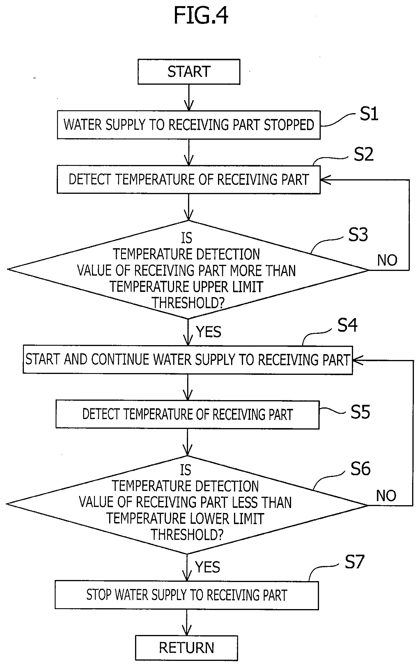
[0016] FIG. 4 is a flowchart for explaining a method of cooling a main roll, according to the First Embodiment of the present invention.
[0017] FIG. 5 is a flowchart for explaining a method of manufacturing a ring rolled body, according to the First Embodiment of the present invention.
[0018] FIG. 6 is a cross-sectional view schematically showing a shaft and a die of a main roll, in a state of being cut along line A-A of FIG. 2, according to a Second Embodiment of the present invention.
[0019] FIG. 7 is a cross-sectional view schematically showing a shaft and a die of a main roll, in a state of being cut along line A-A of FIG. 2, according to a Third Embodiment of the present invention.
DESCRIPTION OF EMBODIMENTS
[0020] Methods of cooling a main roll, methods of manufacturing a rolled body in a substantially ring shape (hereinafter, referred to as a "ring rolled body"), and rolling mills, according to First to Fourth Embodiments of the present invention, will be described below. Note that in a method of cooling a main roll, a shaft and its peripheral portion of a main roll of a rolling mill are mainly cooled. Furthermore, in a method of manufacturing a ring rolled body, while a die of a main roll, in particular, a processed part on the outer peripheral surface of a die being in contact with a material in a substantially ring shape (hereinafter, referred to as a "ring material") are heated, the shaft and its peripheral portion of the main roll are mainly cooled by the cooling method, and furthermore, the ring material is reduced between the main roll and a mandrel. Note that the method of cooling a main roll is also applicable to a method of manufacturing a ring rolled body other than those of the First to Fourth Embodiments of the present invention.
[0021] In the First to Fourth Embodiments of the present invention, a ring rolled body is used for producing a component in a substantially ring shape (hereinafter, referred to as a "ring component"). As an example, a ring component may be a gear, a rotary body of a rotary mechanism, or the like, to be used in various industrial fields. A ring component is preferably one which needs strict dimension control, in particular, for gas turbines, steam turbines, turbine disks used in a jet engine of an aircraft, or the like. As an example, it is preferable that the maximum diameter of the outer periphery of a ring rolled body be equal to or greater than approximately 600 mm but equal to or less than approximately 2000 mm. However, the present invention is not limited thereto. The maximum diameter of the outer periphery of the ring rolled body may be less than approximately 600 mm but greater than approximately 2000 mm, depending on a ring component to be produced with use of the ring rolled body.
[0022] Furthermore, in the First to Fourth Embodiments of the present invention, a ring rolled body is shaped by applying ring rolling to a ring material. In particular, it is preferable that a ring material be produced using a metal material having excellent high-temperature strength, high-temperature toughness, and/or the like. For example, it is preferable that the ring material be produced using a metal material selected from Ni-based alloys, Fe-based alloys, Co-based alloys, Ti-based alloys, and the like which are excellent in high-temperature strength, high-temperature toughness, and/or the like.
First Embodiment
[0023] A method of cooling a main roll, a method of manufacturing a ring rolled body, and a rolling mill, according to a First Embodiment of the present invention, will be described.
[0024] Regarding Rolling Mill
[0025] First, with reference to FIG. 1, a rolling mill to be used in a method of cooling a main roll 1 and a method of manufacturing a ring rolled body, according to the present Embodiment, will be described. A rolling mill is configured such that a ring material M formed so as to be substantially rotationally symmetrical with reference to a central axis C, is attachable and detachable. The rolling mill is also configured such that ring rolling is performed on the ring material M attached thereto.
[0026] Specifically, the rolling mill includes a main roll 1 and a mandrel 2 as described above. The main roll 1 and the mandrel 2 contact an outer peripheral surface m1 and an inner peripheral surface m2 of the ring material M, respectively, and reduce the ring material M in the radial direction thereof (hereinafter referred to as a "ring radial direction") between them. The rolling mill also includes a pair of axial rolls 3, 4. The pair of axial rolls 3, 4 contacts an upper end surface m3 and a lower end surface m4, in a direction of the central axis C, of the ring material M (hereinafter referred to as a "ring axial direction"), and reduces the ring material M in the ring axial direction between them.
[0027] The rolling mill also includes a liquid supply mechanism 5 for supplying water W to cool the main roll 1. As an example, it is preferable that the temperature of the water W is a normal temperature. The rolling mill also includes an induction heating mechanism 6 configured so as to inductively heat the main roll 1. In ring rolling, the ring material M comes into contact with the main roll 1 which is inductively heated by the induction heating mechanism 6.
[0028] However, the present invention is not limited thereto. The rolling mill may be configured as described below. The rolling mill may be configured so as to not include a pair of axial rolls. The liquid supply mechanism may supply liquid other than water, if it is possible to cool the main roll. In particular, the liquid preferably has flame resistance and high fluidity. The liquid may be silicone oil and/or the like, for example. A rolling mill may include a heating mechanism other than an induction heating mechanism, if it is possible to heat the main roll. A heating mechanism may be a gas burner and/or the like, for example.
[0029] Regarding Main Roll and Mandrel
[0030] With reference to FIG. 1, the main roll 1 and the mandrel 2 will be described. The main roll 1 and the mandrel 2 are rotatable about rotation axes 1a, 2a, respectively. Each of the main roll 1 and the mandrel 2 is arranged such that one side in the direction of the rotation axis 1a, 2a (hereinafter referred to as a "rotation axis direction" for each of the main roll 1 and mandrel 2) faces upward.
[0031] Each of the main roll 1 and the mandrel 2 has a shaft 11, 21 extending along the rotation axis 1a, 2a thereof, and a die 12, 22 surrounding the shaft 11, 21. The shaft 11, 21 and the die 12, 22 are different members. The die 12, 22 is attached to the shaft 11, 21. However, the present invention is not limited thereto. In at least one of the main roll and the mandrel, the shaft and the die may be integrated.
[0032] Each of the dies 12, 22 of the main roll 1 and mandrel 2 has an outer peripheral surface 12a, 22a formed in substantially rotationally symmetrical with reference to the rotation axis 1a, 2a. The outer peripheral surfaces 12a, 22a contact the outer peripheral surface m1 and the inner peripheral surface m2 of the ring material M, respectively. Each of the outer peripheral surfaces 12a, 22a of the dies 12, 22 in the main roll 1 and the mandrel 2 has a shape corresponding to the shape of a ring rolled body produced. As an example, the ring material M shown in FIG. 1, is formed to have one protruded portion m5 which protrudes from the outer peripheral surface m1 and extends along the circumferential direction (hereinafter referred to as a "ring circumferential direction") of the ring material M, and the outer peripheral surface 12a of the die 12 of the main roll 1 is formed to have one recessed portion 12b which corresponds to the one protruded portion m5 and extends along the circumferential direction of the main roll 1. However, the present invention is not limited thereto. The outer peripheral surface of the ring material may be formed in a shape other than that having one protruded portion, and the outer peripheral surface of the die of the main roll may be formed corresponding to this outer peripheral surface of the ring material.
[0033] It is preferable that at least one of the main roll 1 and mandrel 2 be rotationally driven by a drive mechanism (not shown). In that case, the drive mechanism may be mounted on at least one of the shafts 11, 21 of the main roll 1 and the mandrel 2. The rotational speed of the main roll 1 and the mandrel 2 may be controllable as required. In particular, it is preferable that only the main roll 1 be rotationally driven. The main roll 1 and the mandrel 2 may also be movable in the ring radial direction as the ring material M is enlarged in the ring diameter direction.
[0034] The ring material M is reduced in the ring radial direction between the outer peripheral surfaces 12a, 22a of the dies 12, 22 of the main roll 1 and the mandrel 2, in a state of rotating in the ring circumferential direction along with the rotation of the main roll 1 and the mandrel 2. Note that in the method of manufacturing a ring rolled body described below, description will be in the case in which the main roll 1 rotates to one side (indicated by arrow R1) in the rotational direction thereof and the mandrel 2 rotates to one side (indicated by arrow R2) in the rotational direction thereof, and along with this rotation, the ring material M rotates toward one side of the ring circumferential direction (indicated by arrow F).
[0035] Furthermore, the main roll 1 may have a size which can be heated by the induction heating mechanism 6 but is difficult to be heated by a heating furnace, a gas burner, and/or the like. In particular, it is preferable that the maximum diameter of the outer peripheral surface 12a of the die 12 of the main roll 1 be approximately 1000 mm or greater. However, the present invention is not limited thereto. The maximum diameter of the outer peripheral surface of the die in the main roll may be less than approximately 1000 mm, if the main roll can be heated appropriately.
[0036] Cooling Structure of Main Roll
[0037] With reference to FIGS. 2 and 3, a cooling structure of the main roll 1 will be described. The die 12 of the main roll 1 has a receiving part 13 which is recessed downward from the upper end surface 12c. The receiving part 13 opens at the upper end surface 12c of the die 12, and extends in the circumferential direction of the main roll 1 so as to surround the shaft 11. The receiving part 13 receives water W supplied from the liquid supply mechanism 5.
[0038] The die 12 of the main roll 1 also includes a plurality of liquid passages 14 extending from the receiving part 13 toward the other side of the rotation axis direction. The liquid passages 14 are spaced apart from one another (each other) in the circumferential direction of the main roll 1. As an example, the die 12 shown in FIGS. 2 and 3, has four liquid passages 14. However, the present invention is not limited thereto. The die can have two or more liquid passages. In particular, it is preferable that the die have three or more liquid passages.
[0039] Furthermore, the die 12 has a mounting hole 15 which penetrates so as to allow the shaft 11 to be inserted. The mounting hole 15 extends from a bottom surface 13b of the receiving part 13 to the lower end surface 12d of the die 12 along the rotation axis 1a of the main roll 1. The shaft 11 is mounted on the die 12 in a state of being inserted in the mounting hole 15.
[0040] In the cooling structure of the main roll 1, the receiving part 13 has: an opening edge 13a located at the upper end surface 12c of the die 12; the bottom surface 13b facing the opening edge 13a; and an inner peripheral surface 13c extending between the opening edge 13a and the outer peripheral edge of the bottom surface 13b.
[0041] When considering prevention of a temperature drop in the processed part on the outer peripheral surface 12a of the die 12 which contacts the ring material M, and prevention of a decrease in the strength of the die 12, it is preferable that the bottom surface 13b of the receiving part 13 be positioned above the processed part of the die 12. As an example, when the main roll 1 rotates, the liquid, such as water W in the receiving part 13 is applied with centrifugal force. Therefore, the bottom surface 13b is preferably formed so as to have a depth in the receiving part 13 in which the liquid can be held within the receiving part 13. The bottom surface 13b may be formed in a substantially flat shape along the horizontal direction.
[0042] Furthermore, when considering prevention of a temperature drop in the outer peripheral surface 12a of the die 12, and prevention of a decrease in the strength of the peripheral portion of the shaft 11 in the die 12, it is preferable that the maximum distance from the rotation axis 1a of the main roll 1 to the inner peripheral surface 13c of the receiving part 13 be equal to or less than 3/4 of the minimum distance from the rotation axis 1a of the main roll 1 to the outer peripheral surface 12a of the die 12, and more preferably, it be equal to or less than 1/2 of the minimum distance. The inner peripheral surface 13c is formed along the vertical direction. However, the present invention is not limited thereto. The inner peripheral surface may be inclined against the vertical direction. For example, the inner peripheral surface may be formed so as to taper off from the bottom surface of the receiving part toward the opening edge.
[0043] Furthermore, in the cooling structure of the main roll 1, each of the liquid passages 14 has: an inlet 14a which opens at the receiving part 13; and an outlet 14b which opens at the lower end surface 12d of the die 12. Each liquid passage 14 may also communicate with the mounting hole 15 in the radial direction of the main roll 1. In particular, it is preferable that each liquid passage 14 be formed so as to be recessed from the inner peripheral surface 15a of the mounting hole 15. It is also preferable that each liquid passage 14 extend along the shaft 11. However, the present invention is not limited thereto. At least one of the liquid passages may be spaced apart from the mounting hole 15 in the radial direction of the main roll.
[0044] Regarding Liquid Supply Mechanism
[0045] With reference to FIG. 1, the liquid supply mechanism 5 of the rolling mill will be described. The liquid supply mechanism 5 includes: a supply pipe 51 in which water W can pass through the supply pipe 51; and a valve 52 provided to the supply pipe 51. At the distal end of the supply pipe 51, a supply port 51a for supplying water W to the receiving part 13, is formed. The supply port 51a is positioned above the receiving part 13. The valve 52 is openable and closable so as to switch the state between a state in which the water W flows out of the supply port 51a, and a state in which outflow of the water W is stopped. In particular, it is preferable that the valve 52 be adjustable for the opening and closing amount so as to adjust the supply amount of the water W from the supply port 51a.
[0046] The liquid supply mechanism 5 also has a temperature detection unit 53 capable of detecting the temperature of the receiving part 13 of the main roll 1. It is preferable that the temperature detection unit 53 detect the temperature of the receiving part 13 in a non-contact manner. As an example, the temperature detection unit 53 may be a radiation thermometer. However, the present invention is not limited thereto. The temperature detection unit may be able to detect the temperature of the water discharged from the outlet of the die.
[0047] The liquid supply mechanism 5 also includes a control unit 54 which enables control of supply of the water W from the supply pipe 51 to the receiving part 13. The control unit 54 is electrically connected to the valve 52 and the temperature detection unit 53. The control unit 54 receives a temperature detection value of the receiving part 13 from the temperature detection unit 53. The control unit 54 also controls open and close of the valve 52 according to the temperature detection value. In particular, it is preferable that the control unit 54 be able to control the opening and closing amount of the valve 52. As an example, the control unit 54 may be a control unit including an electric component, such as a CPU, an electric circuit, and/or the like.
[0048] Regarding Induction Heating Mechanism
[0049] The induction heating mechanism 6 of the rolling mill will be described. Although not shown in particular, the induction heating mechanism 6 includes an induction heating coil having a winding wound around at least once. In this induction heating mechanism 6, a line of magnetic flux for induction heating is generated when an alternate current flows through the winding of the induction heating coil.
[0050] As shown in FIG. 1, the induction heating mechanism 6 is disposed around the outer peripheral surface 12a of the die 12 in the main roll 1 so as to inductively heat the processed part (including the recessed part 12b) of the outer peripheral surface 12a of the die 12. In particular, it is preferable that the induction heating mechanism 6 be placed in a region (hereinafter referred to as a "region immediately before inner and outer periphery reduction region") adjacent to the other side in the rotation direction of the main roll 1, with respect to the reduction region (hereinafter referred to as an "inner and outer periphery reduction region") between the main roll 1 and the mandrel 2, around the outer peripheral surface 12a of the die 12. As an example, it is preferable that the region immediately before inner and outer periphery reduction region be located within a range of a length obtained by dividing the entire peripheral length of the main roll 1 into four, from the inner and outer periphery reduction region to the other side in the rotation direction of the main roll 1. However, the present invention is not limited thereto. The induction heating mechanism may inductively heat an edge-shape contact part of the main roll, which contacts the edge-shaped part formed on the outer peripheral surface of the ring material.
[0051] Regarding Method of Cooling Main Roll
[0052] A method of cooling the main roll 1, according to the present Embodiment will be described with reference to FIGS. 1 and 4. First, the valve 52 is closed, and supply of the water W from the supply pipe 51 is stopped (Step S1). A temperature detection value of the receiving part 13 is obtained by the temperature sensor 52 (Step S2). By the control unit 54, it is determined whether or not the temperature detection value of the receiving part 13 is greater than a pre-determined temperature upper limit threshold (Step S3).
[0053] When the temperature detection value of the receiving part 13 is equal to or less than the temperature upper limit threshold (NO), the process returns to the work of obtaining a temperature detection value of the receiving part 13 by the temperature sensor 52 before the determination (Step S2). On the other hand, when the temperature detection value of the receiving part 13 is greater than the temperature upper limit threshold (YES), the valve 52 is opened to supply the water W from the supply pipe 51 to the receiving part 13 (Step S4). Note that before supplying of the water W to the receiving part 13, pre-processing to prevent generation of scale may be applied to the water W. Next, by the temperature sensor 52, a temperature detection value of the receiving part 13 is obtained again (Step S5). It is determined whether or not the temperature detection value of the receiving part 13 is less than a temperature lower limit threshold (Step S6).
[0054] When the temperature detection value of the receiving part 13 is equal to or greater than the temperature lower limit threshold (NO), supply of the water W to the receiving part 13, is continued (Step S4). When the temperature detection value of the receiving part 13 is less than the temperature lower limit threshold (YES), the valve 52 is closed to stop supply of the water W to the receiving part 13 (Step S7). Note that the supply rate of the water W to the receiving part 13 may be adjusted corresponding to the temperature detection value of the receiving part 13.
[0055] The work described above may be performed repeatedly in a situation in which the die 12 of the main roll 1 is inductively heated by the induction heating mechanism 6, and thereby, temperature distribution in the shaft 11 and the die 12 of the main roll 1 may be controlled appropriately. It is suitable that this cooling method be performed in a state in which the main roll 1 rotates. However, it is possible to perform it in a state in which the rotation of the main roll 1 is stopped. Note that at least one of the works in the cooling method may be performed manually by an operator.
[0056] In the cooling method, the temperature upper limit threshold and the temperature lower threshold may be defined as described below. It is preferable that the temperature upper limit threshold be approximately 150 degrees C., and that the temperature lower limit threshold be approximately 40 degrees C. That is, it is preferable that the temperature detection value of the receiving part 13 be maintained between approximately 40 degrees C. or more, but approximately 150 degrees C. or less.
[0057] However, the present invention is not limited thereto. The temperature upper limit threshold may be more than the temperature lower limit threshold, and the temperature upper limit threshold may be less than the temperature of the receiving part determined corresponding to the heat resistance temperature of the bearing part on the basis of the heat conduction conditions from the receiving part of the die to the bearing part of the shaft.
[0058] Regarding Method of Manufacturing Ring Rolled Body
[0059] A method for manufacturing a ring rolled body, according to the present Embodiment will be described with reference to FIGS. 1 and 5. In the manufacturing method, a process of controlling the temperature of the main roll 1 so as to cool the shaft 11 and the peripheral portion thereof of the main roll 1 while heating the die 12 of the main roll 1 (hereinafter referred to as a "temperature control process"), and a process of performing ring rolling on the pre-heated ring material M (hereinafter referred to as a "rolling process") are performed. Regarding the rolling process, it is preferable that the temperature of the pre-heated ring material M be approximately 850 degrees C. or more, but approximately 1150 degrees C. or less. However, the temperature of the ring material is not limited thereto. It is adjustable according to the type of the metal material used for the ring material so as to produce a high quality ring rolled body.
[0060] First, the temperature control process is performed. Specifically, the main roll 1 is rotated (Process P1). A work to inductively heat the main roll 1 by the induction heating mechanism 6 (hereinafter referred to as an "induction heating work") and a work to cool the main roll 1 by the cooling method (hereinafter referred to as a "cooling work") are started (Process P2). Thereafter, when the temperature distribution in the shaft 11 and the die 12 of the main roll 1 has been properly controlled (Process P3), the induction heating work and the cooling work terminate (Process P4). Furthermore, rotation of the main roll 1 is stopped (Process P5). Note that during the energization of the induction heating mechanism 6, when a problem, such as electrical ground fault or the like arises, it is preferable to stop supply of the water W from the liquid supply mechanism 5 to the receiving part 13.
[0061] Next, the rolling process is performed. Specifically, the pre-heated ring material M is mounted on the rolling mill (Process P6). The main roll 1 and the mandrel 2 are rotated, and the pair of axial rolls 3, 4 is rotated. Along with the rotation, the ring material M is rotated toward the one side (indicated by arrow F) in the ring circumferential direction about the central axis C thereof (Process P7). The induction heating work is started again (Process P8). A work to reduce the ring material M in the ring radial direction by the main roll 1 and the mandrel 2, and a work to reduce the ring material M in the ring axial direction by the pair of axial rolls 3, 4, are repeated in this order (hereinafter referred to as a "reduction work") (Process P9). At this time, the main roll 1 and mandrel 2 are moved relative to the ring radial direction with reference to the center in the radial direction of the ring material M, whereby the ring material M can be deformed so as to increase its diameter. When the ring material M is deformed into a desired shape (Process P10), the reduction work terminates. At the same time, the induction heating work on the main roll 1 terminates (Process P11). Thereafter, rotation of the ring material M is stopped (Process P12). Note that the induction heating work need not be stopped temporarily and may continue during transition from the temperature control process to the rolling process. The cooling work may be performed during the reduction work. After the termination of the rolling process, if the shaft 11 and the peripheral portion thereof of the main roll 1 have residual heat in particular, it is preferable to further perform the cooling work.
[0062] Regarding Details of Induction Heating Work
[0063] Here, details of the induction heating work will be described. As described above, the induction heating work is performed in a substantially continuous manner during the time from the start thereof until the start of the reduction work, and it is also performed during reduction of the ring material M. Before the reduction work, the induction heating work is performed so as to cause the temperature of the processed part of the outer peripheral surface 12a of the die 12 in the main roll 1 to be a pre-determined temperature (hereinafter referred to as a "pre-reduction heating temperature) for a pre-determined time (hereinafter referred to as a "pre-reduction heating time"). During the reduction work, the induction heating work is performed so as to cause the temperature of the processed part of the outer peripheral surface 12a of the die 12 in the main roll 1 to be a pre-determined temperature (hereinafter referred to as an "in-reduction heating temperature").
[0064] The pre-reduction heating time, the pre-reduction heating temperature, and the in-reduction heating temperature may be as described below. Considering: heating the die 12 of the main roll 1 sufficiently before the reduction work so as to efficiently enhance the quality of the ring rolled body to be produced; and performing induction heating during the reduction work, the pre-reduction heating time may be approximately 3 minutes or more, and the pre-reduction heating temperature may be approximately 100 degrees C. or more. The pre-reduction heating temperature is preferably approximately 150 degrees C. or more, and is more preferably, approximately 300 degrees C. or more.
[0065] On the other hand, considering preventing softening of the main roll 1 and preventing reduction in the manufacturing efficiency of the ring rolled body, the pre-reduction heating time may be approximately one hour or less, and the pre-reduction heating temperature may be less than the softening temperature of the material of the main roll 1. Specifically, in the case in which the material of the outer peripheral surface 12a of the die 12 in the main roll 1 is steel for hot-working die defined by JIS G4404 or improved steel thereof, the pre-reduction heating temperature is preferably less than the tempering temperature. That is, the softening temperature may be the tempering temperature. In the case in which the material of the main roll 1 requires strength and heat resistance, a Ni-based superalloy may be used. In that case, the pre-reduction heating temperature is preferably less than the solution treatment temperature. That is, the softening temperature may be the solution treatment temperature.
[0066] Furthermore, the in-reduction heating temperature preferably ranges from approximately 300 degrees C. to the temperature of the pre-heated ring material M. The upper limit value is preferably set according to the material and/or the like of the main roll 1. In particular, the upper limit value is preferably set to a temperature which enables the main roll 1 to be prevented from softening. That is, the in-reduction heating temperature is preferably less than the softening temperature of the die 12 in the main roll 1, in the same manner as the pre-reduction heating temperature.
[0067] Furthermore, the temperature of the induction heating by the induction heating mechanism 6 is preferably adjusted such that the temperature distribution in the radial direction of the ring material M is efficiently controllable within an appropriate temperature range while suppressing heat extraction of the ring material M, within the aforementioned range. As an example, the temperature of the induction heating by the induction heating mechanism 6 is preferably adjusted to equalize the temperature distribution in the radial direction of the ring material M.
[0068] However, the present invention is not limited thereto. The method of manufacturing a ring rolled body may be made as described below. The induction heating work may terminate before or after the termination of the reduction work. The timing of restarting the induction heating work after temporal interruption before the start of the reduction work of the ring material may be immediately before the start of, at the start of, or after the start of the reduction work of the ring material. In particular, the interruption time of the induction heating work is preferably set within a range in which the temperature of the main roll which can efficiently enhance the quality, such as dimension accuracy of the ring rolled body to be produced, is maintained. Furthermore, the reduction work may be performed in a state in which the induction heating work is stopped. In that case, the pre-reduction heating time may be approximately 15 minutes or more, but approximately 2 hours or less, and is preferably approximately 30 minutes or more, but approximately 1 hour or less.
[0069] Actions and Effects
[0070] As described above, in the method of cooling the main roll 1 according to the present Embodiment, the receiving part 13 which is recessed from the upper end surface 12c of the die 12 of the main roll 1 and surrounds the shaft 11 of the main roll 1, receives the water W, and the main roll 1 is cooled by the water W in the receiving part 13. Therefore, the shaft 11 can be cooled efficiently. On the other hand, the receiving part 13 is apart from the processed part (including the recessed part 12b) of the outer peripheral surface 12a of the die 12 which contacts the ring material M. Therefore, it is possible to efficiently prevent a temperature drop in the processed part of the die 12 and the ring material M which contacts it. Accordingly, the shaft 11 and the peripheral portion thereof of the main roll 1 can be cooled efficiently. Since the receiving part 13 widely opens toward the outside of the main roll 1 at the upper end surface 12c of the die 12, it is possible to easily clean the inside thereof from the opening of the receiving part 13. Therefore, maintenance of the main roll 1 can be performed easily. Since the receiving part 13 is formed in the die 12, it is possible to prevent the strength of the shaft 11 from being decreased by the cooling structure of the main roll 1. Therefore, the strength of the rotation support structure of the main roll 1 can be secured sufficiently.
[0071] In the method of cooling the main roll 1 of the present Embodiment, the water W injected in the receiving part 13 flows through the liquid passages 14 which extend from the receiving part 13 toward the other side in the rotation axis direction in the die 12 and are spaced apart from each other in the circumferential direction of the main roll. Therefore, the water W is stored in the receiving part 13, and thereafter, the water W in the receiving part 13 is sent to the liquid passages 14. As a result, the water W is retained in the main roll 1 so as to enable the main roll 1, in particular, the shaft 11, to be cooled efficiently. Furthermore, since the liquid passages 14 provided to the main roll 1 in addition to the receiving part 13, are spaced apart from each other in the circumferential direction of the main roll 1, it is possible to prevent the strength of the main roll 1 from being decreased by the added liquid passages 14. That is, the strength of the main roll 1 can be secured sufficiently.
[0072] In the method of cooling the main roll 1 of the present Embodiment, the water W flowing through the liquid passages 14, is discharged from the outlets 14b of the liquid passages 14 which open at the lower end surface 12d of the die 12 of the main roll 1, to the outside of the main roll 1. Therefore, since the water W in the main roll 1 is replaceable, the main roll 1 can be cooled effectively.
[0073] In the method of manufacturing the ring rolled body of the present Embodiment, even if the die 12 of the roll 1 is heated, the shaft 11 of the main roll 1 can be efficiently cooled by the cooling method. Compared with the case of directly heating the ring material M which is deformed during ring rolling, heating the main roll 1 which maintains a certain shape, causes the temperature control in the hot ring rolling to be easier. That is, it is possible to accurately control the temperature of the processed part of the die 12 which applies hot ring rolling to the ring material M, while cooling the shaft 11 which is necessary to be prevented from being exposed to high temperature. Therefore, a high-quality ring rolled body can be produced by the hot ring rolling using the main roll 1 which enables accurate temperature control as described above.
Second Embodiment
[0074] A method of cooling a main roll, a method of manufacturing a ring rolled body, and a rolling mill, according to a Second Embodiment of the present invention, will be described. The method of cooling the main roll and the method of manufacturing the ring rolled body, according to the present Embodiment, are the same as those of the First Embodiment. The rolling mill according to the present Embodiment is the same as that of the First Embodiment except for the liquid passages in the cooling structure of the main roll.
[0075] Regarding Liquid Passage in Cooling Structure of Main Roll
[0076] With reference to FIG. 6, a liquid passage 16 in the cooling structure of the main roll 1 will be described. A die 12 of the main roll 1 of the present Embodiment includes a plurality of liquid passages 16 which are formed in a blind hole shape, instead of the liquid passages 14 which penetrate through as in the First Embodiment. Each of the liquid passages 16 has an inlet 16a which opens at the receiving part 13, and a bottom 16b which is positioned at the lower end thereof. The other configurations of the liquid passage 16 are the same as those of the liquid passage 14 of the First Embodiment.
[0077] Actions and Effects
[0078] As described above, in the method of cooling the main roll 1 of the present Embodiment, the actions and effects as described below can be achieved, instead of the actions and effects provided by the liquid passages 14 which penetrate in the method of cooling the main roll 1 of the First Embodiment. That is, since the water W flowing into the liquid passage 16 which is formed in a blind hole shape, is stored on and above the bottom 16b of the liquid passage 16, the water W evaporates in the main roll 1, and furthermore, by the heat of vaporization due to evaporation, the main roll 1, in particular the shaft 11 and the peripheral portion thereof of the main roll 1 can be cooled effectively. Note that the other actions and effects based on the method of cooling the main roll 1 according to the present Embodiment and the actions and effects based on the method of manufacturing the ring rolled body are the same as those of the First Embodiment.
Third Embodiment
[0079] A method of cooling a main roll, a method of manufacturing a ring rolled body, and a rolling mill, according to a Third Embodiment of the present invention, will be described. The method of cooling the main roll and the method of manufacturing the ring rolled body, according to the present Embodiment, are the same as those of the First Embodiment. The rolling mill according to the present Embodiment is the same as that of the First Embodiment except for the receiving part in the cooling structure of the main roll.
[0080] Regarding receiving part in cooling structure of main roll With reference to FIG. 7, a receiving part 17 in the cooling structure of the main roll 1 will be described. A die 12 of the main roll 1 in the present Embodiment has a receiving part 17 which is recessed downward from the upper end surface 12c thereof. The receiving part 17 opens at the upper end surface 12c of the die 12, and extends in the circumferential direction of the main roll 1 so as to surround the shaft 11. The receiving part 17 receives the water W supplied from the liquid supply mechanism 5.
[0081] The receiving part 17 includes an opening edge 17a which is formed on the upper end surface 12c of the die 12, a bottom surface 17b facing the opening edge 17a, and an inner peripheral surface 17c located between the opening edge 17a and the outer peripheral edge of the bottom surface 17b. The bottom surface 17b is formed in a recessed shape in a tapered manner toward the inlet 14a of the liquid passage 14. Therefore, the water W in the receiving part 17 can be efficiently guided to the liquid passage 14 by the bottom surface 17b. Furthermore, an upper area of the inner peripheral surface 17c has a protrusion 17d which protrudes to the rotation axis 1a side of the main roll 1 relative to the lower area. Therefore, by the protrusion 17d, it is possible to prevent the water W in the receiving part 17 from leaking outside from the opening of the receiving part 17 during rotation of the main roll 1.
[0082] It is also preferable that the bottom surface 17b of the receiving part 17 be located above the processed part of the outer peripheral surface 12a of the die 12, in the same manner as the First Embodiment. As an example, in the same manner as the First Embodiment, since centrifugal force is applied to the liquid, such as the water W in the receiving part 17 during rotation of the main roll 1, the bottom surface 17b may be formed so as to realize a depth of the receiving part 17 which can hold the liquid in the receiving part 17. Furthermore, in the same manner as the First Embodiment, the maximum distance from the rotation axis 1a of the main roll 1 to the inner peripheral surface 17c of the receiving part 17 may be equal to or less than 3/4 of the minimum distance from the rotation axis 1a of the main roll 1 to the outer peripheral surface 12a of the die 12, and may be preferably, equal to or less than a half of the minimum distance.
Fourth Embodiment
[0083] Regarding a method of cooling a main roll, a method of manufacturing a ring rolled body, and a rolling mill according to a Fourth Embodiment of the present invention, the method of cooling the main roll and the method of manufacturing the ring rolled body are the same as those of the Second Embodiment. Furthermore, the rolling mill according to the present Embodiment is the same as that of the Second Embodiment, except that the die of the main roll has the receiving part in the same manner as that of the Third Embodiment.
[0084] Although Embodiments of the present invention have been described, the present invention is not limited to the Embodiments described above. The present invention can be modified and changed based on the technical concept.
[0085] For example, as a First Modification of the present invention, the die of the main roll in the First to Fourth Embodiments may have a plurality of liquid passages including: a liquid passage/liquid passages penetrating as in the First and Third Embodiments; and a liquid passage/liquid passages formed in a blind hole shape as in the Second and Fourth Embodiments.
[0086] As a Second Modification of the present invention, the die of the main roll in the First to Fourth Embodiments may be configured so as not to have a liquid passage.
REFERENCE SIGNS LIST
[0087] 1 Main roll, 1a Rotation axis, 11 Shaft, 12 Die, 12c Upper end surface, 12d Lower end surface, 13 Receiving part, 13b Bottom surface, 14 Liquid passage, 14b Outlet, 16 Liquid passage, 16b Bottom, 17 Receiving part, 17b Bottom surface, 2 Mandrel, M Ring material, m1 Outer peripheral surface, m2 Inner peripheral surface, W Water, S1 to S6 Step, P1 to P12 Process, R1, R2, F Arrow
* * * * *
D00000
D00001
D00002
D00003
D00004
D00005
XML
uspto.report is an independent third-party trademark research tool that is not affiliated, endorsed, or sponsored by the United States Patent and Trademark Office (USPTO) or any other governmental organization. The information provided by uspto.report is based on publicly available data at the time of writing and is intended for informational purposes only.
While we strive to provide accurate and up-to-date information, we do not guarantee the accuracy, completeness, reliability, or suitability of the information displayed on this site. The use of this site is at your own risk. Any reliance you place on such information is therefore strictly at your own risk.
All official trademark data, including owner information, should be verified by visiting the official USPTO website at www.uspto.gov. This site is not intended to replace professional legal advice and should not be used as a substitute for consulting with a legal professional who is knowledgeable about trademark law.